Page 98 HONDA INTEGRA 1994 4.G Owner's Guide
[x] Cancel search | Manufacturer: HONDA, Model Year: 1994, Model line: INTEGRA, Model: HONDA INTEGRA 1994 4.GPages: 1413, PDF Size: 37.94 MB
Page 99 of 1413
wEc
6-38
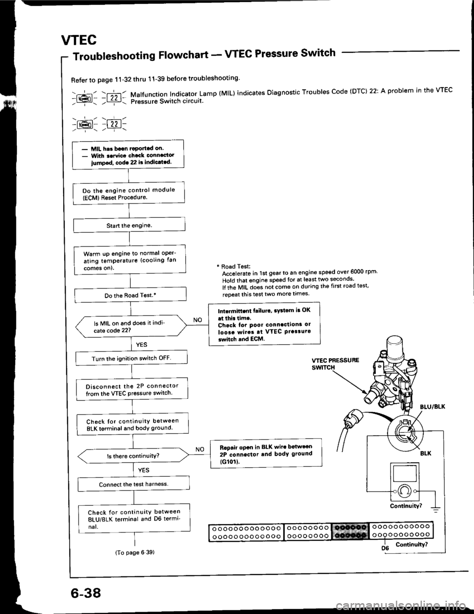
Troubleshooting Flowchart - VTEC Pressure Switch
Refer to page 11-32thru 11-39 beJore troubleshooting'
-.+- -r";-r- Malfunction Indicator Lamp (MlL) indicates Oiagnostic Troubles Code (DTC) 22: A problem in the VTEC- l{{?l- ;l ziz r: pressur€ Switch circuit.
-lr@l- |22 1-
* Road Test:Accolerato in lst gear to an engine speed over 6000 rpm
Hold that engine speed for at least two seconos'
lf the MIL does not come on during the first road test'
reoeat this test two more limes.
- MIL har bagn.oportcd on.- With t.rvic. chack connactor
iump.d, cod€ 22 it indic.t.d.
Do the engine control module(ECM)Reset Procedure.
Warm !p engine to normal oper-
ating temperstur€ (cooling fan
comes on).
Do the Boad T€st.'
Intc.mift.nt failu.o, ry3tom ia OK
at thi. tim..Chack for pool connaction3 ol
loo!. rvirat at VTEC Ptasturo3whch and ECM.
ls MIL on and does it indi'
cate code 22?
Turn lhe ignition switch OFF
Disconnect the 2P connector
lrom the VTEC Pressure switch.
Check Ior continuity between
BLK terminal and body ground.
Rcpair opcn in BLK wit. botwcon
2P connector rnd body ground
tG101l.
Check for continuity between
8LU/8LK terminal and D6 termi'
nal.
(To page 6 39)
Page 100 of 1413
(From page 6-38)
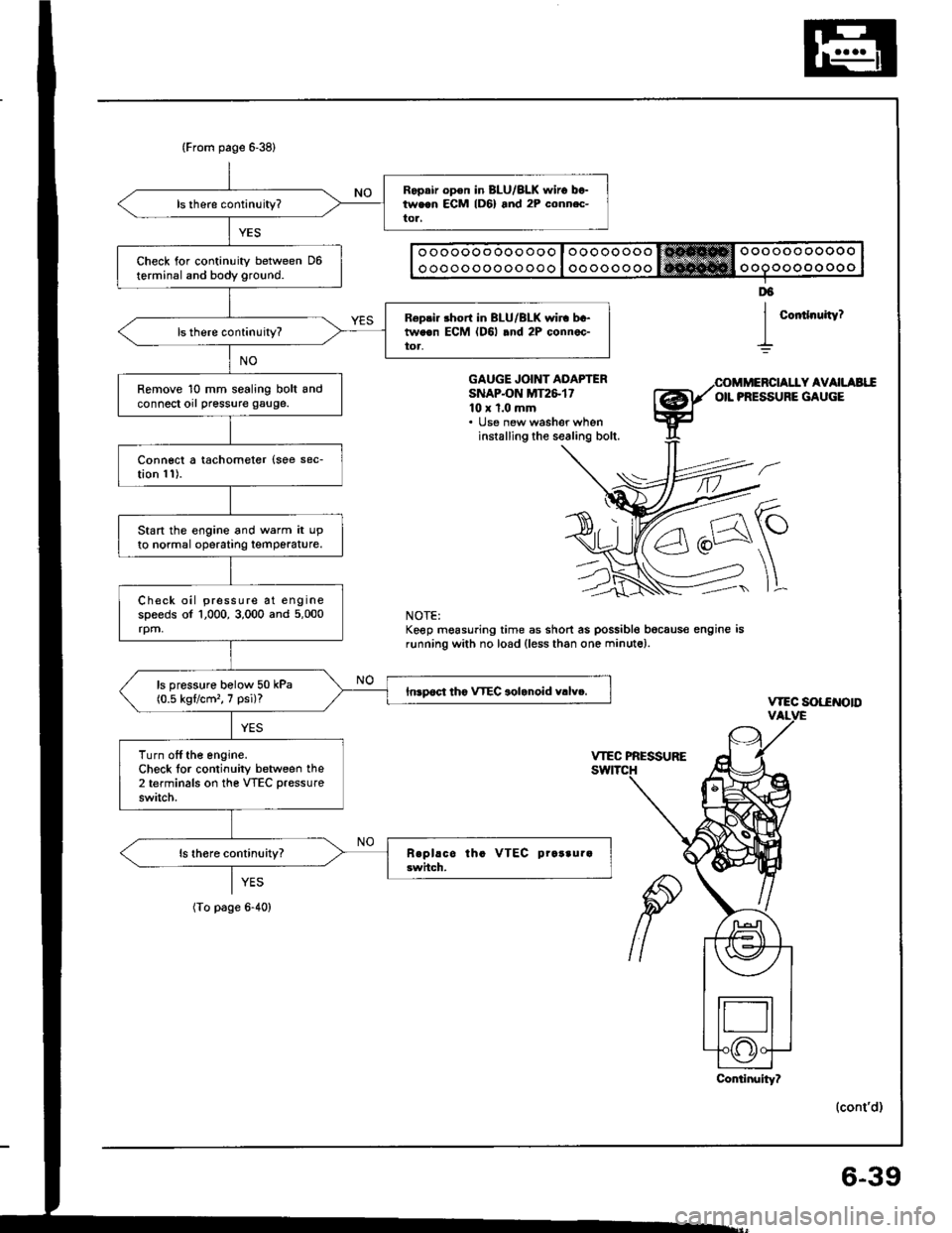
Ropair op€n in BLU/BLK $,iro between ECM lD6) and 2P conn.c-tor,
Check for continuity between D6terminal and body ground.
R6pri. short in BLU/BLK wir. bc-tweon ECM (D6l .nd 2P connec-toa,
Remove 10 mm sealing bolt andconnect orl pressure gauge.
Connect a tachometer {soe sec-tion 11).
Start the engine and warm it upto normal operatrng temperature.
Check oil pressure at enginespeeds of 1,000, 3,000 and 5,000rpm,
ls pressure bolow 50 kPa(0.5 kgflcm'�, 7 psi)?Inrpoct tho VTEC aolanoid v.lv..
Turn off the engine.Check lor continuity between the2 terminals on the VTEC pressure
switch.
o oooooo ooo ooo I oooooooo trt!*Hffi Oooooo ooooo
o oooo ooooo ooo I oo oooo ooo ooooo oo oo o
Coitlnuity?
D6
I
GAUGE JOINT ADAPTERSNAPON MT2&1710 x 1.0 mm. lJse new washer wheninstalling the sealing bolt.
Y AVAILAEIIOIL PRESSURE GAUGE
\-
]L
vtEc sot-€NotD
(cont'd)
NOTE:Keep mgasuring time as short as possible bocaus€ engine isrunning with no load (less than one minute).
YES
(To page 6-40)
Conlinuity?
6-39
Page 103 of 1413
VTEC
Rocker Armsnlrungf rtrrrri' - rYrorrtrcr rrrDPEUtrl,rl
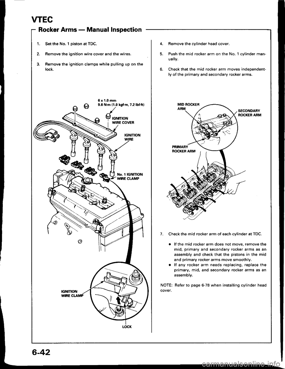
1. Set rh6 No. I Diston at TDC.
2. Remove the ignition wire cover and the wires.
3. Remove the ignition clamps while pulling up on the
lock.
4.Remove the cylinder head cover.
Push the mid rocker arm on the No. 1 cylinder man-
ually.
Check that the mid rocker arm moves independent-
ly of the primary and secondary rocker arms.
6 x 1.0.nm9.8 N.m 11.0 lgfm, 7.2 lbf.ftl
SECONDARYROCKER ARM
7. Check the mid rocker arm of each cvlinder at TDC.
. lf the mid rocker arm does not move, remove the
mid, primary and secondary rocker arms as an
assembly and check that the pistons in the mid
and primary rocker arms move smoothly.
. lf any rocker arm needs replacing, replace the
primary, mid, and secondary rocker arms as an
assemblv.
NOTE: Refer to page 6-78 when installing cylinder head
cover.
w
Page 104 of 1413
Rocker Arms - Inspection Using Special Tools
CAUTION:
. Boforo using tho valvo inspoction tool. make 3uro
that th6 air prsssure gaugs on th6 air comprossol
indicatG over 250 kPa {2.5 kgf/cm'�, 36 psi}
. Inspect the valvs clearanco befors rockel lrm insPoc-
tion.
. Covor the timing belt with a shop towsl to pl€vent
qotting oil on lhe b6lt.
. Check ths mid rocker srm of oach cylindor at TDC.
1. Remove the cylinder head cover.
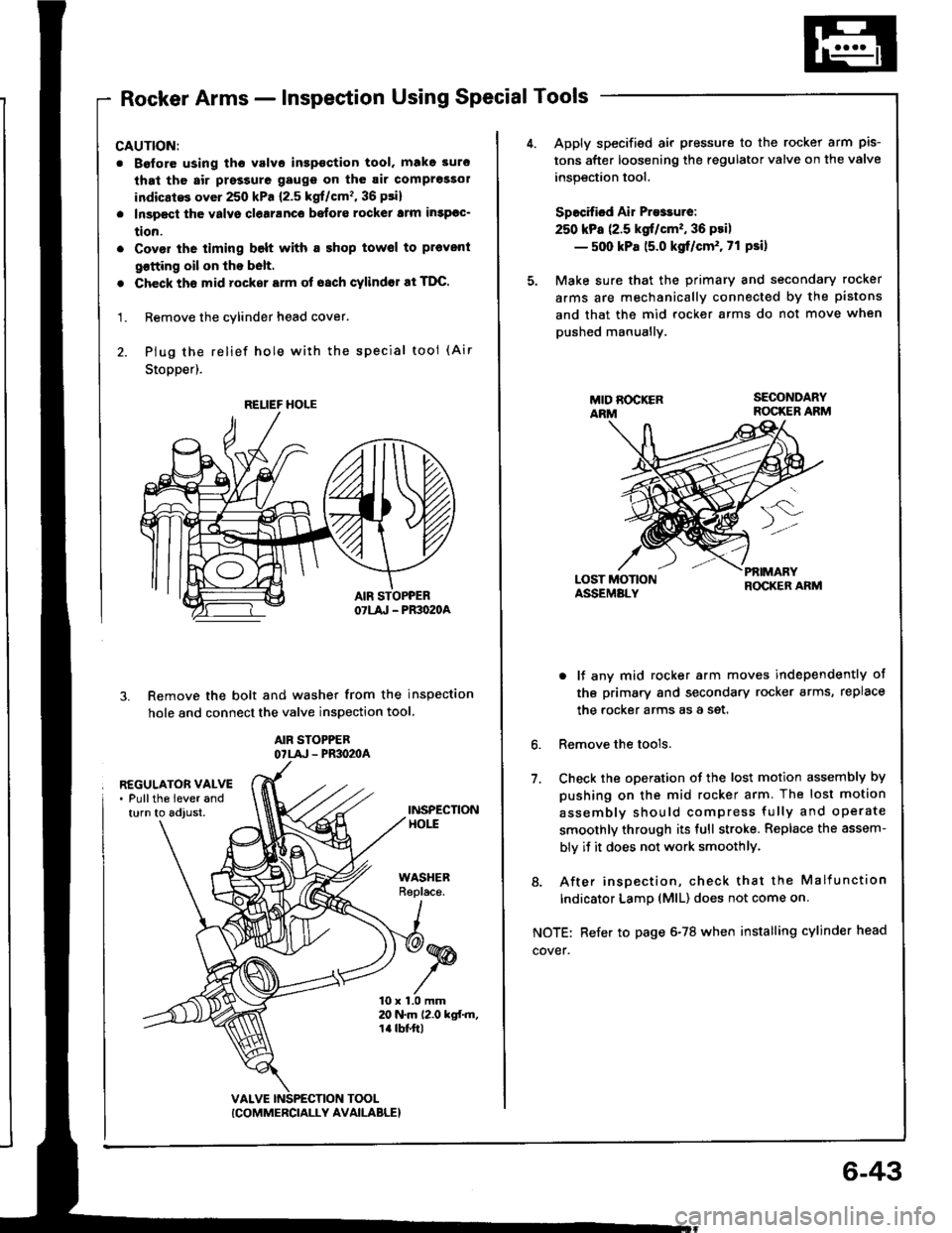
2. Plug the relief hole wiih the special tool (Air
Stopper).
Remove the bolt and washer from the inspection
hole and connect the valve inspection tool
AIR STOPPEBOTLA' - PR3O2OA
3.
REGULATOR VALVE. Pullths lever andturn to adjust.INSPECTIONHOtt
WASHERReplace.
10 x 1.0 mm20 N.m 12.0 kgf.m,1a tbt'ft|
TOOL
RELIEF HOLE
ICOMMERCIALLY AVAILABLE}
6-43
Apply specified air pressure to the rocker arm pis-
tons after loosening the regulator valve on the valve
inspection tool.
Specified Air Presrure:
250 kPa (2.5 kgt/cm'�, 36 psi)
- 500 kPa 15.0 kgf/cm'. 71 Psi)
Make sure that the primary and secondary rocker
arms are mechanically connected by the pistons
and that the mid rocker arms do not move when
pushed manuallv.
LOST MOTIONASSEMALY
PfiIMARYROCKER ARM
6.
7.
o lf any mid rocker arm moves independently of
tho primary and secondary rocker arms, replace
the rocker arms as a set.
Remove the tools.
Check the oDeration of the lost motion assembly by
pushing on the mid rocker arm. The lost motion
assemblv should compress fully and operate
smoothly through its full stroke. Replace the assem-
bly if it does not work smoothlY.
8. After insoection, check that the Malfunction
Indicator LamD (MlL) does not come on
NOTE: Refer to page 6-78 when installing cylinder head
cover.
Page 106 of 1413
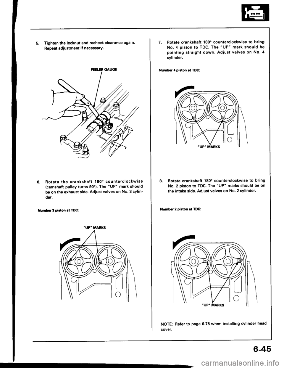
Tightsn the locknut and recheck clearance again.
Rep6at sdjustm6nt if necossary.
Rotsts tha crankshaft 180' counterclockwiss
(c8mshaft pulley turns 90'). The "UP" mark should
be on th€ sxhaust 8id6, Adiust vslves on No. 3 cylin-
oer,
Nurrb.r3tittondTDC:
FEEI.IR GAUGE
.UP' MANKS
7. Rotato crankshaft 180' countsrclockwise to bring
No.4 piston to TDC. The "UP" mark should bo
pointing straight down. Adjust valves on No. 4
cylinder.
Numb.r 4 pidon .t Tt C:
8, Rotate crankshaft 180" counterclockwis€ to bring
No. 2 piston to TDC. The "UP" marks should be on
the intaks sid6. Adjust valves on No. 2 cylinder.
Nonb.r 2 pirton .l TltC:
NOTE: Refer to page 6-78 when installing cylinder head
cover.
6-45
Page 107 of 1413
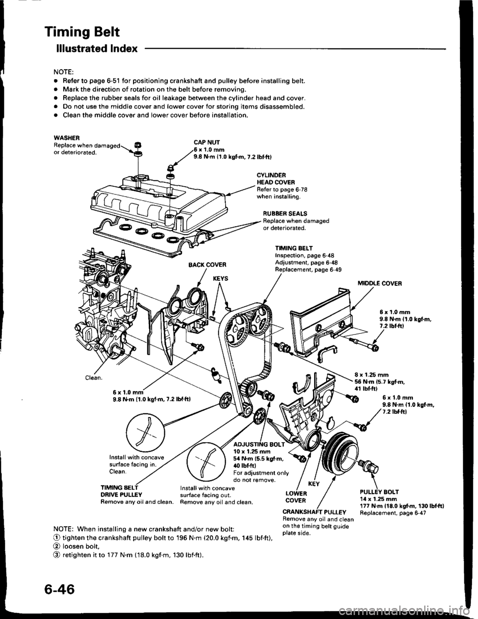
Timing Belt
. ReJerto page 6-51 for positioning crankshaft and pulley before installing belt.. Mark the direction of rotation on the belt before removing.
. Replace the rubber seals for oil leakage between the cylinder head and cover.. Do not use the middle cover and lower cover for storing items disassembled.
. Clean the middle cover and lower cover before installation.
lllustrated lndex
NOTE:
WASHERReplace whenCAP NUTx 1,0 mm9.8 N.m 11.0 kgf.m,7,2lbttrlor deteriorated.
CYLINDERHEAO COVERReter to page 6'78when installing.
RUBBER SEALSReplace when damagedor deteriorated,
TIMING BELTInsp€ctaon, page 6-48Adjustment. page 6-48R€placement. page 6'49
MIDDLE COVER
5xl,0mm9.8 N.m (1.0 kgt m,7.2 rbtftt
8 x 1.25 mm56 N.m 15.7 kgt m,41 tbtftl6x1.0mm9.8 N.m (1.0 kgt.m,7.2lbf ftl6x1.0mm9.8 N.m {1.0 kgl.m,7.2lbf.ftl
Installwith concavesurface lacing in.Clean.
TIMING SELDRIVE PULLEYRemove any oil and clean.
10 x 1.25 mm5a N.m 15.5 kgl.m.(} tbf.ftlFor adiustment onlydo not remove.
BOLTInstallwith concavesurface tacing out.Remove any oiland clesn.1il x 1.25 mm177 N.m 118,0 kgtm, 130lbtft)Replacement, page 6-47
COVER
PULLEYRemove any oil and cleanon the timing belt guideplate side.NOTE: When installing a new crankshaft and/or new bolt:
O tighten the crankshaft pulley bolr to 196 N.m (20.0 kgf.m. 145 lbf.ft),
@ loosen bolt,
@ retighten it to 177 N.m fl8.0 kgf.m, 130 lbnft).
3-E
6-46
Page 109 of 1413
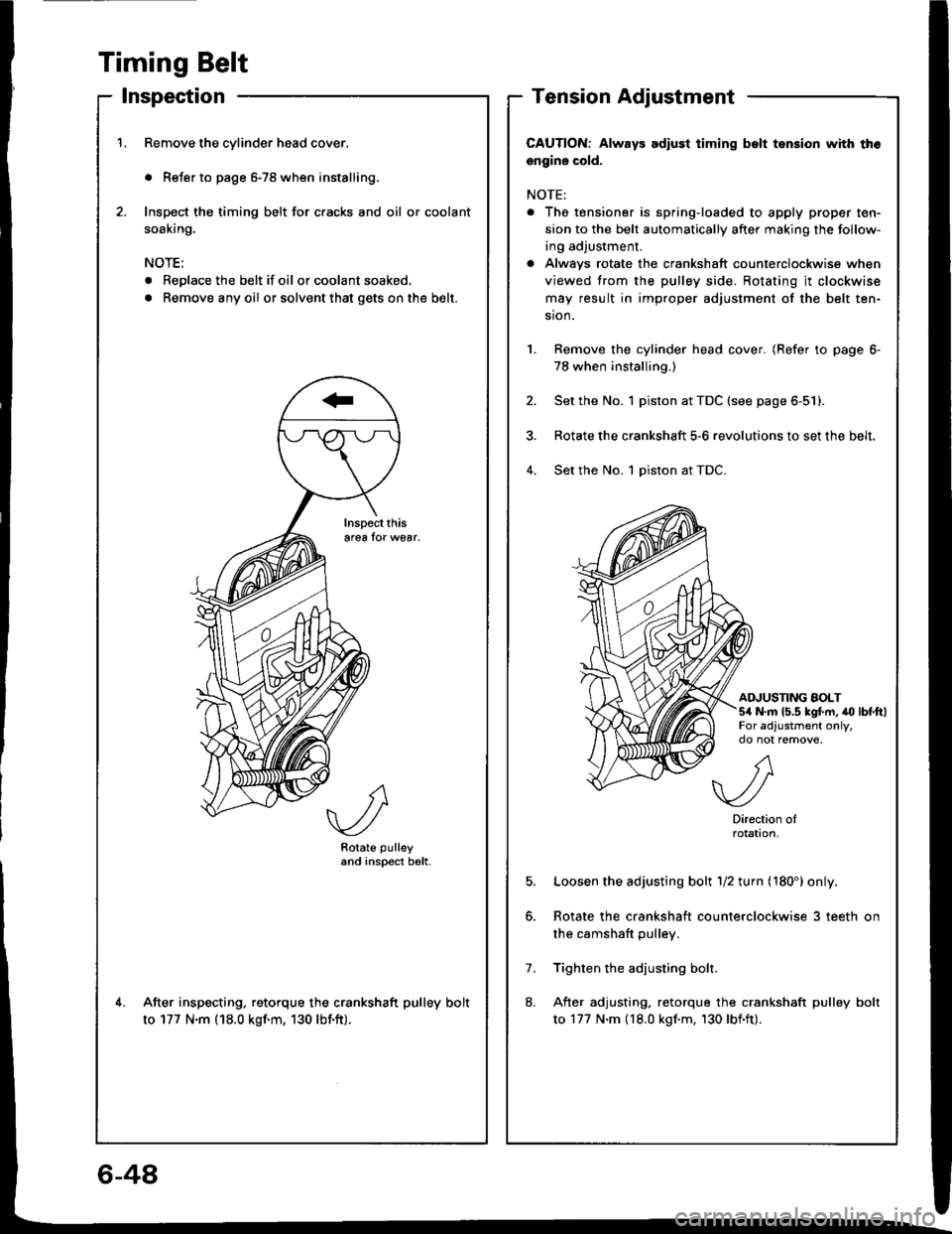
Timing Belt
lnspection
Remove the cylinder head cover.
. Refer to page 6-78 when installing.
Inspect the timing belt for cracks and oil or coolant
soaking.
NOTE:
. Replace the belt if oil or coolant soaked.
. Remove any oil or solvent that gets onthe b€lt.
Rotate pulleyand inspect b6lt.
After inspecting. retorque the crankshaft pulley bolt
to 177 N.m (18.0 kgf.m, 130 lbf.ft).
Tension Adjustment
CAUTION: Always adlust timing bslt tsnsion with th6
engine cold.
NOTE:
. The tensioner is spring-loaded to apply proper ten-
sion to the belt automatically after making the follow-
ing adjustment.
a Alwavs rotate the crankshaft counterclockwise when
viewed trom the pulley side. Rotating it clockwise
may result in improper adjustment of the belt ten-
sion.
Remove the cylinder head cover. (Refer to page 6-
78 when installing.)
Set the No. 1 piston at TDC (see page 6-51).
Rotate the crankshaft 5-6 revolutions to set the belt.
Set the No. 1 piston at TDC.4.
AINUSTING AOLT5/a N.m 15.5 kg{.m, to lbtftlFor adjustment only,
5.
7.
8.
A
.//\v-/
Directionrotat|on,
Loosen the adjusting bolt 1/2 turn (180') only.
Rotate the crankshaft counterclockwise 3 teeth on
the camshaft pulley.
Tighten the adjusting bolr.
After adjusting, retorque the crankshaft pulley bolt
to 177 N.m (18.0 kgf.m, 130 lbf'ft).
6-48
Page 110 of 1413
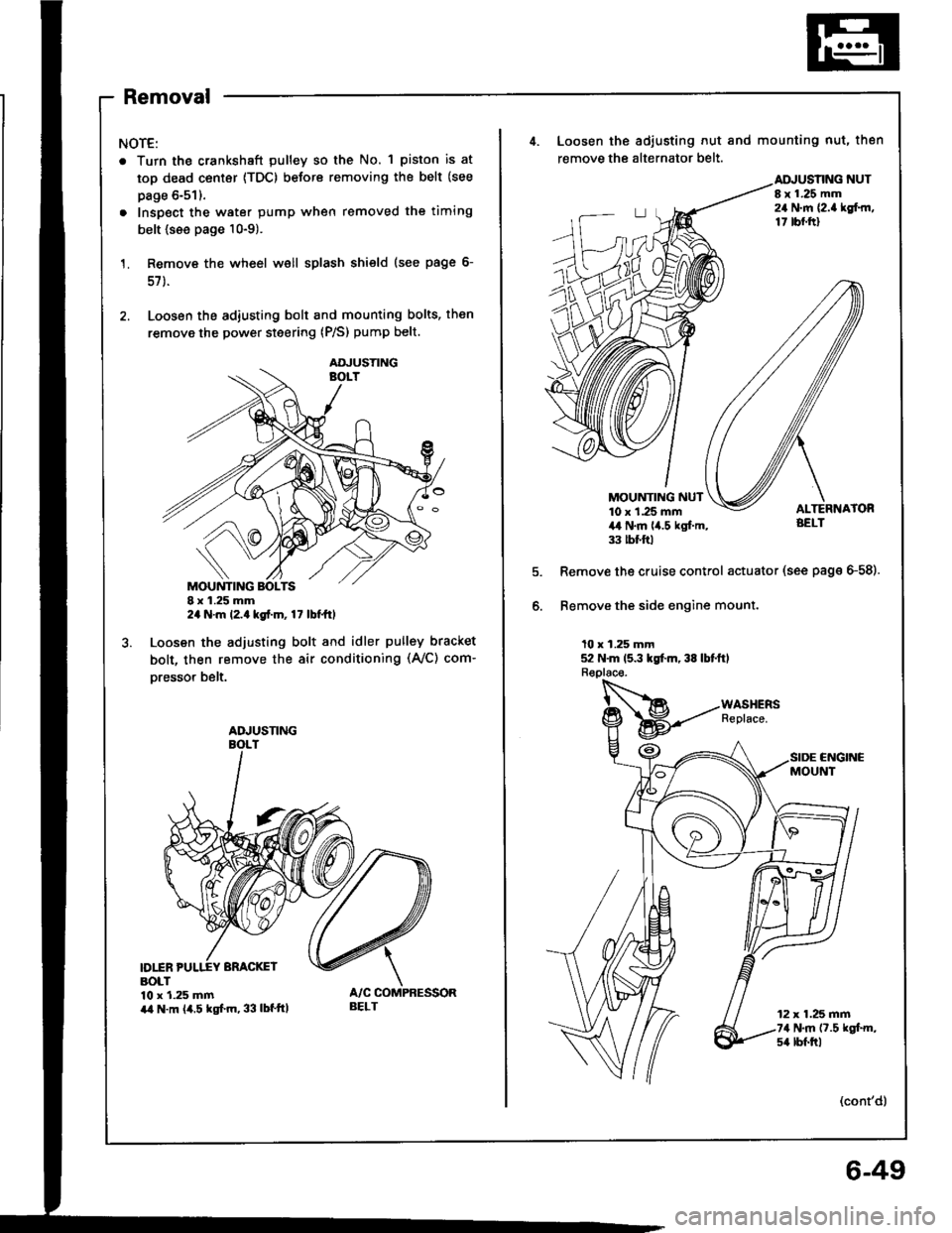
Removal
NOTE:
. Turn the crankshaft pulley so the No. 1 piston is at
top dead center {TDC) before removing the belt (see
page 6-51).
. Inspect the water pump when removed the timing
belt {see page 10-9).
Remove the wheel well splash shield (see page 6-
57 ).
Loosen the adiusting bolt and mounting bolts, then
remove the power steering (P/S) pump belt.
I x 1.25 mm2a N.m l2.a kgt.m, 17 lbt ttl
Loosen the adjusting bolt and idler pulley bracket
bolt, then remove the air conditioning (Ay'C) com-
oresso. belt.
D1INBOLT10 x 1.25 mmira N.m (4.5 kgf.m, 33 lbf'ttl
AOJUSTING
ADJUSNNG
BELT
4. Loosen the adiusting nut and mounting nut, then
remove the alternator belt.
NUTI x 1.25 mm24 N.m {2.a lgf.rn,17 tbf.ftl
MOUNTING NUT10 x 1.25 mm4,t N.m lia.5 kgl.m,33 tbt ftl
Remove the cruise control actuator (see page G58).
Bemove the side engine mount.
10 x 1.25 mm52 N.m 15.3 kgt m, 38 lbtftl
CNGINCMOUNT
12 x 1.25 mm74 N.m (7.5 kgt m,s4 lbf.trl
(cont'd)
6-49
Page 111 of 1413
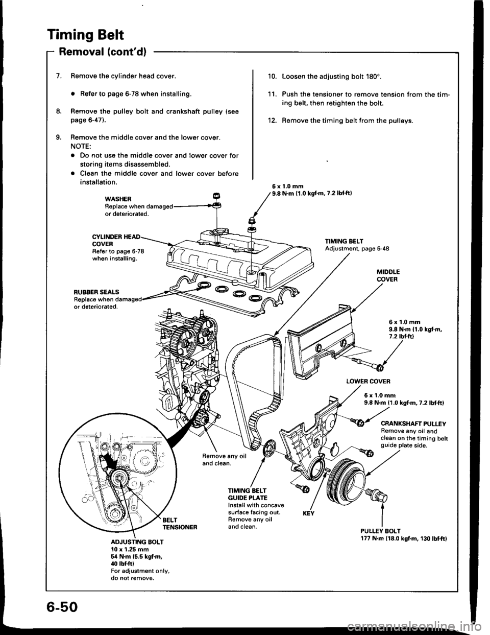
Timing Belt
Removal lcont'd)
1.Remove the cylinder head cover.
. Refer to page 6-78 when installing.
Remove the pulley bolt and crankshaft pulley (see
page 6-47).
Remove the middle cover and the lower cover.
NOTE:
. Do not uss the middle cover and lower cover for
storing items disassembled.
a Clean the middle cover and lower cover before
installation.
Loosen the adjusting boh 180'.
Push the tensioner to r€move tension from the tim-
ing belt, then retighten the bolt.
Remove the timing belt from the pulleys.
10.
12.
11.
8.
a
6x1.0mm9.8 N.m 11,0 kgf'm, 7.2 lbl'ftlWASHERReplace whenor deteriorated.
CYLINDEROOVERRel€r to pago 6-78when inslalling.
NMING BELTAdjustment, page 6-48
MIDDLECOVER
RUABER SEALSReplac6 whenor deteriorated.
6x1.0mm9.8 N.m {1.0 kgf.m,7.2 rbnftl
LOWER COVER
6r1.0mm9.8 N.m 11.0 kgf.m,7.2lbtftl
CRANKSHAFT PULl"EYRemove any oil andclean on the timing beltguide plat6 side.
BELTTENSIONER
TIMING BELTGUIDE PLATElnstallwith concavesurface facing out.Remove any oiland clean.PULI.TY BOLT17? N m {18.0 kgf.m, 130lbtftlADJUSNI{G BOLT10 x 1,25 mm5,t N.m 15.5 kgf.m,.(l rbf.fttFor adjustm€nt only,
@^Rv@
Page 113 of 1413
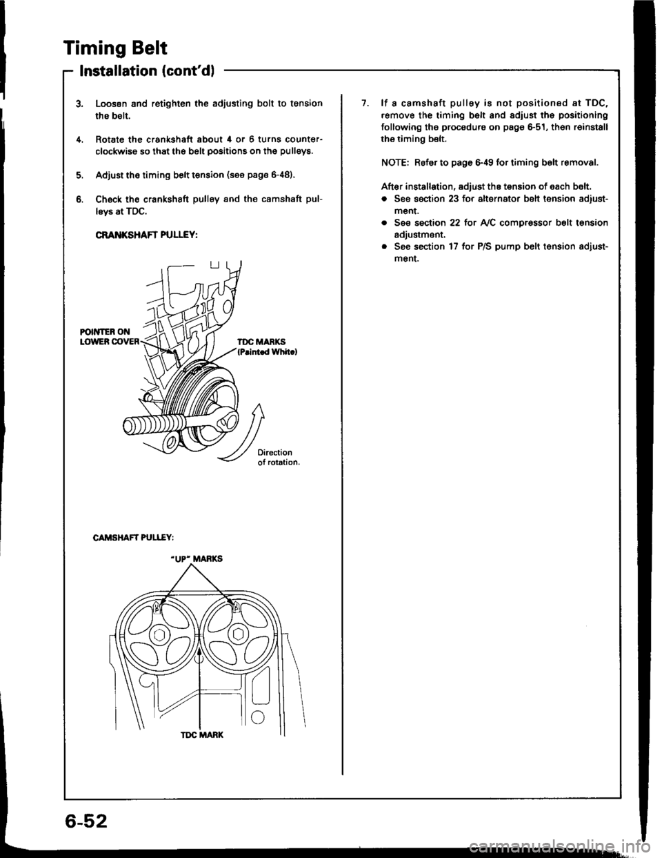
Timing Belt
Installation (cont'dl
1Loosen and retighten the adjusting bolt to tsnsion
thB belt.
Rotate the crankshaft about 4 or 6 turns countsr-
clockwise so that the belt positions on the pulleys.
Adjust ths timing bolt tension (see pags &48).
Ch€ck ths crankshaft pullsy and the camshaft pul-
lsys at TDC.
CRANKSHAFT PULLEY:
1.lf a camshaft pulley is not positioned at TDC.
.emove the timing belt and adiust the positioning
following the procedure on page 6-51, th6n r6install
rhe riming belt.
NOTE: Refsr to page 6,19 for timing b€lt removal.
Aft€r installation, adiust the tension of each b€lt.
o See section 23 for alternator belt tension adiust-
menr.
. See section 22 tot NC compr€ssor b6lt tension
adjustm€nt.
. See section 17 for P/S pump b6lt t€nsion adiust-
menL
4.
5.
b.
CAMSHAFT PULI..EY:
"UP- MANKS
6-52