ecm connector HONDA INTEGRA 1994 4.G Workshop Manual
[x] Cancel search | Manufacturer: HONDA, Model Year: 1994, Model line: INTEGRA, Model: HONDA INTEGRA 1994 4.GPages: 1413, PDF Size: 37.94 MB
Page 98 of 1413
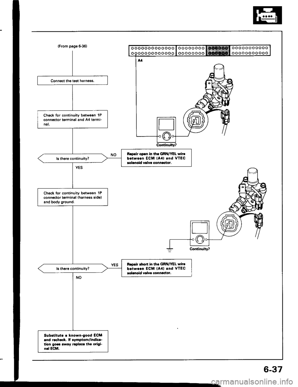
{From pag6 636}
ContinuityT
ooooooooooo
ooooooooooo
ooooooooooooo
ooooooooooooo
Ch6ck for continuity botw6en 'lP
connector t€rminal and A4 termi-nal.
B.9.lr op.n in th. GRI{/YEL wircb.tw..n ECM {Aa} .od vTEcaolanoid valva connac'tor.
Ch6ck for continuity botwoon 1Pconnector terminal (harness side)and body ground.
Ro.ir .hon i|r th. GRN/VEL wirc
b.iw..n ECM (A4l .nd VTECaoldroid valv. Gonnac'tor.
Sub.titut! . krown-good ECM|r|d r.ch!ck. lt .ytnptom/indic!-tion gor3 away rrplact tha origi-n.l Ecttl,
6-37
Page 99 of 1413
wEc
6-38
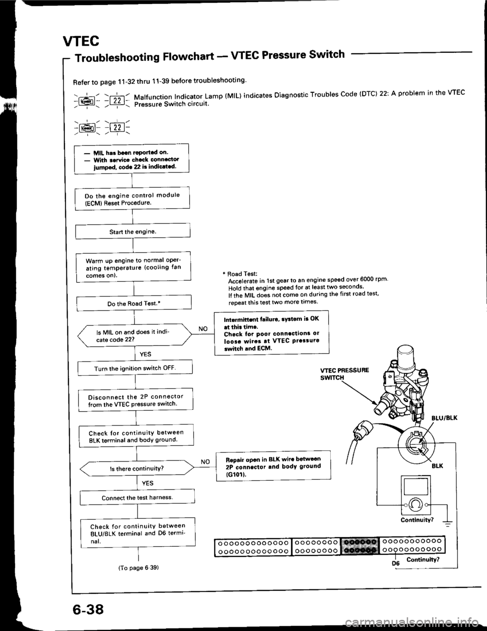
Troubleshooting Flowchart - VTEC Pressure Switch
Refer to page 11-32thru 11-39 beJore troubleshooting'
-.+- -r";-r- Malfunction Indicator Lamp (MlL) indicates Oiagnostic Troubles Code (DTC) 22: A problem in the VTEC- l{{?l- ;l ziz r: pressur€ Switch circuit.
-lr@l- |22 1-
* Road Test:Accolerato in lst gear to an engine speed over 6000 rpm
Hold that engine speed for at least two seconos'
lf the MIL does not come on during the first road test'
reoeat this test two more limes.
- MIL har bagn.oportcd on.- With t.rvic. chack connactor
iump.d, cod€ 22 it indic.t.d.
Do the engine control module(ECM)Reset Procedure.
Warm !p engine to normal oper-
ating temperstur€ (cooling fan
comes on).
Do the Boad T€st.'
Intc.mift.nt failu.o, ry3tom ia OK
at thi. tim..Chack for pool connaction3 ol
loo!. rvirat at VTEC Ptasturo3whch and ECM.
ls MIL on and does it indi'
cate code 22?
Turn lhe ignition switch OFF
Disconnect the 2P connector
lrom the VTEC Pressure switch.
Check Ior continuity between
BLK terminal and body ground.
Rcpair opcn in BLK wit. botwcon
2P connector rnd body ground
tG101l.
Check for continuity between
8LU/8LK terminal and D6 termi'
nal.
(To page 6 39)
Page 101 of 1413
VTEC
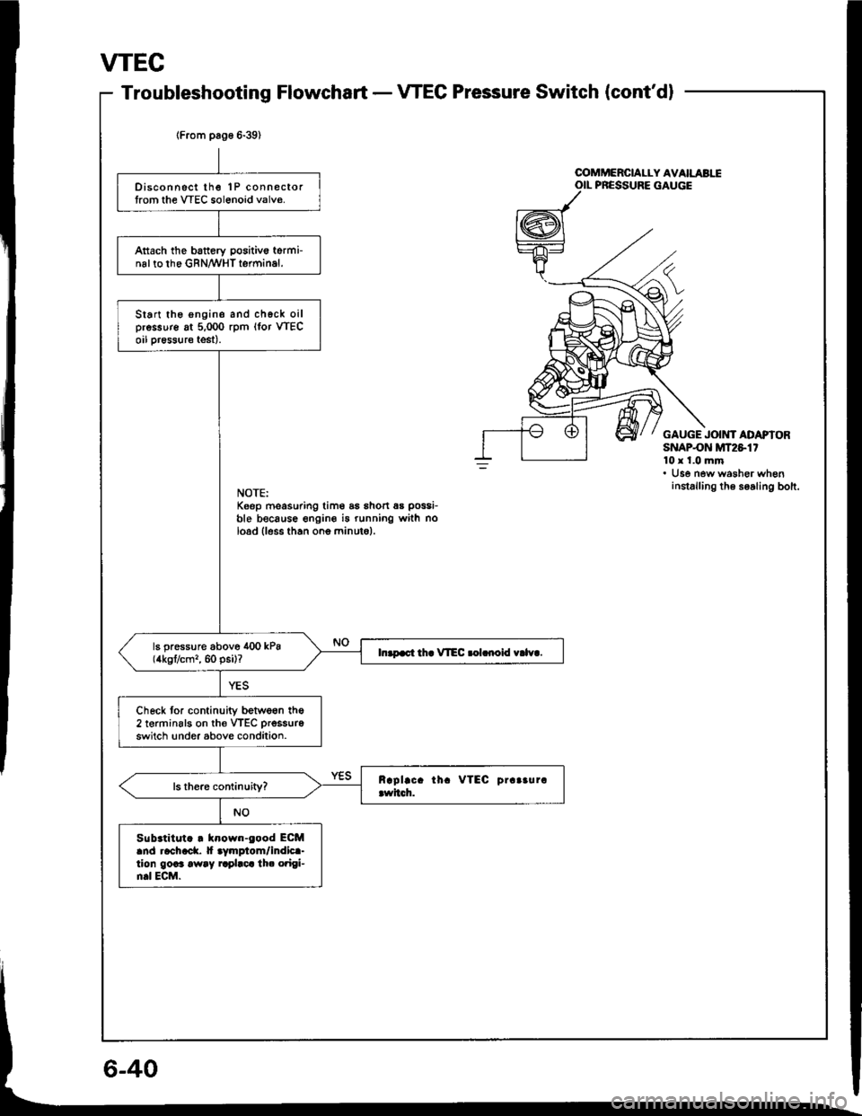
Troubleshooting FlowchartVTEC Pressure Switch (cont'dl
lFrom pag6 6-39)
Disconnsct lhe 1P connectortrom the VTEC sol6noid valve.
Attach the battery positivo torminal to the GRN/WHT terminal.
Start the engine and chgck oilpressure at 5,000 rpm (lor VTECoil pr€ssure test).
ls pressure above 400 kPa(4kgt/cm,, 60 psi)?In.p.ct th. VIEC .olrnoid v.lv..
Check tor continuity betwe6n the2 terminsls on th€ VTEC prsssure
switch !nder above condition.
Sub.titut. . klown-eood ECMand rachack. |f aymplom/indica-tion goaa away rrplaca th. o?igi-n.l ECM.
u
OOMMERCIALLY AVAILABIIOIL PRESSURE GAUGE
GAUGE JOIMf ADAPIORSNAPON MT2S1'10x 1.0 mm. Use new washer wheninstalling th6 soaling bolt.NOTE:Keep moasuring tim6 as shon 6s possi-
ble because engine i5 running with noload lless than ono minuto).
Page 198 of 1413
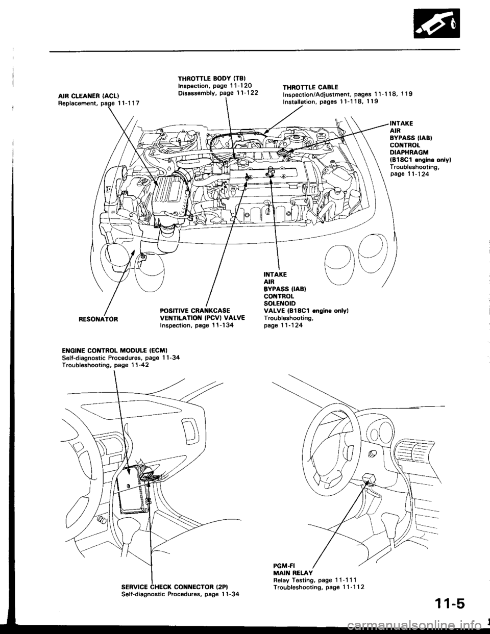
AIR CLEAI{ER IACL)Replacoment,11-117
THROTTLE BODY (T8I
Inspsction, page 1 1-120Disassembfy, page 11'122THROTTLE CABLEInsDection/Adjustment, pages 1 l-'l 18, 1 19
Inslallation, pages 1 1-1 18, 119
POSITIVE CRA KCASEvEt{TtLATtOt{ (PcVl VALVEInspection, psgo 1 l-134
INTAKEAIREYPASS IIABIco TnoLSOLENOIDVALVE (B18Cl .ngino onlylTroubl6shooting,page 1 1-124
INTAKEAIRBYPASS (IABI
co TROLOIAPHRAGM{Bl8C1 ongino onlylTroubleshooting,page 11-124
I
RESONATOR
ENGI]TE CONTROL MODULE {ECM)Selt-diagnostic Procedures, page 1 1-34Troubfeshooting, page 1 1 -42
MAIN RELAYRelay Testing, page 1 1- 111Troubleshooting, pag€ 1 1-112SERVICE CHECX CONNECTOR (2PI
56ll.diagnostic Procedures, page'l 1-34
11-5
Page 221 of 1413
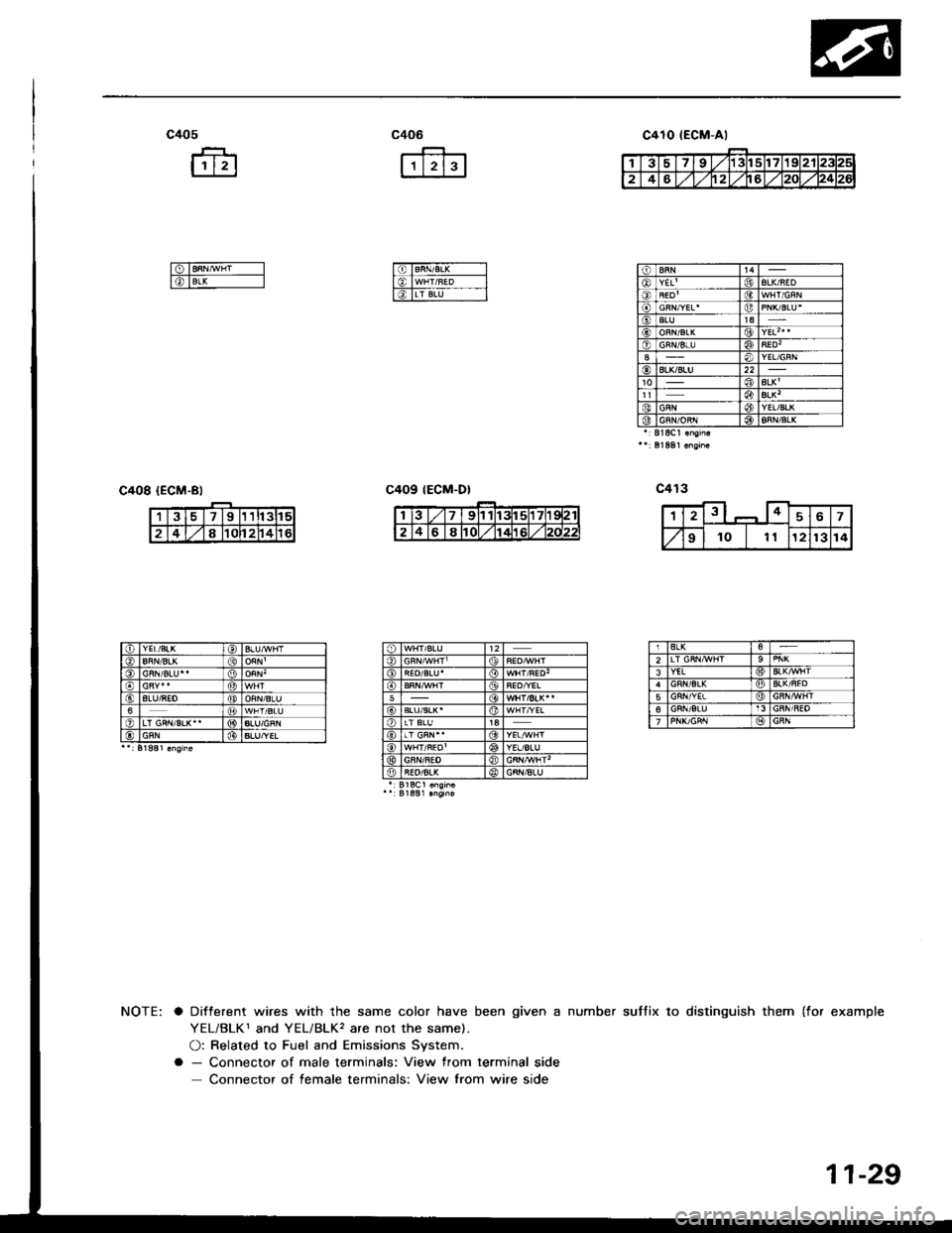
c405
fr
ffi
c406
r'tr--Jl
I6TBRN/B,L( -----l
l€, lwHr/uED -__-l
l6TLr BN--- l_l
c408 {ECM-Bl
suffix to distinguish them (for examplea Different wires with the same color have been given a number
YEL/BLK1 and YEL/BLK, are not the same).
O: Related to Fuel and Emissions System.
a - Connector of male terminals: View from terminal side
Connector of female terminals: View from wire side
c410 tEGM-Al
tt4YEL'| (jtALK/AED
SLU1aALKt(9YEL| 0o)
ALK'ALK'YEL/BLKGRN/oRr l@BLK
391t3tl5
2481Cl24
IALU/REO6
ALU/YEL
BLK2YEL
56
11-29
Page 224 of 1413
Troubleshooting
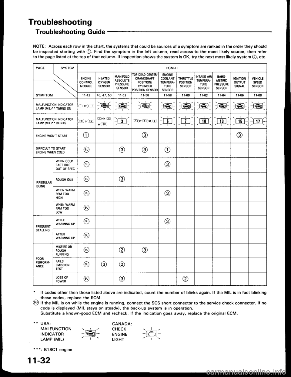
Troubleshooting Guide
NOTE: Across each row in the chart. the systems that could be sources of a symptom are ranked in the order they should
be inspected staning with O. Find the symptom in the left column, read across to the most likely source. then refer
to the page listed at the top of that column. lf inspection shows the system is OK, try the next mosr likely system O, etc,
* lf codes other then those listed above are indicated, count the number of blinks again. It the MIL is in fact blinking
^ these codes, replace the ECM.
qy, lf the MIL is on while the engine is running. connect the SCS shon connector to the service check connector. It no
code is displayed {MlL stays on steady), the back-up system is in operation.
Substitute a known-good ECM and recheck. lf the indication goes away, replace the original ECM.
USA:
MALFUNCTION
INDICATOR
LAMP {MIL)
CANADA: ----l CHECK-ltGl- ENGTNE- | - LTGHT
- { -1t-
* * *: 818C1 engine
1-32
SYMPTOM
PGM.FI
ENGINECONTROLMOOULE
HEATEOOXYGENSENSOR
MANIFOLOAESOLUTEPRESSURESENSOR
TOP DEAD CINTTR/CRANKSHAFTPOSTT|ON/CYLINDERPOSITION SENSOR
ENGINECOOLANTTEMPfRA.TURTSENSOR
THROTTTEPOStTtONSENSOR
INfAKE AIRTEMP€RA.TUREsar,rs0R
BARO.METRICPRESSURESENSOR
IGNITIONOUTPUTSIGNAL
vEHtct-ESPfEDSENSOR
11.4246, 47,5011-56l1-581l-6011-6211-641t-661r-68
MALFUNCTION INOICATORLAMP (MIU" TURNS ON1 lor:t:]:lrmr:- i;:i'-tK3t-16l-16l'-\-16l/-----\
-r:+r-
-{"Pr:-o_-16l-.z-\r6t/_-\
MALFUNCTION INOICATORLAMP (MIL)'' BLINKS:O. or-8.-D:o.:@.
o, O'l3l/__-\.E-o.:O: or tr]--i !l/ -i-\| 7 t-/__-\
--l-l-l r0 I/----\| 13 |z_---\
\.--r--l
I r5 t-/.---\-t 17 t-/-]-\
ENGINE WON'T STAffTo@@
DIFFICULT TO STARTENGIN€ WHEN COLO@@(9)o
IRREGULARIDLING
WHEN COTDFAST IDLEouT 0f sPtc@@
ROUGH IDLE@o
RPM TOOHIGH@@
RPM TOOLOW@
FREOUENTSTALLING
WHILE@@
AFTER@
POOnPERFOEM.ANCE
MISFIRE ORROUGHRUNNING@@@
FAITSEMISSIONTEST@@@
Loss 0FPOWER@@@
Page 227 of 1413
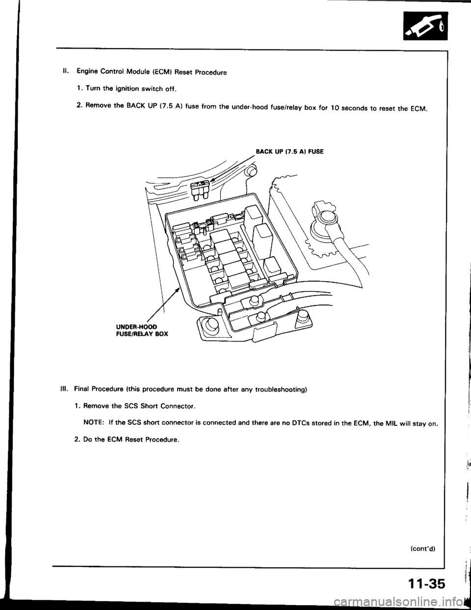
Engine Control Modute {ECM) Reset procedure
1 . Turn the ignition switch otJ.
2' Remove th€ BACK UP (7.5 A) fuse trom the unde.-hood fuse/relay box for lo seconds to reset the EcM.
BACK UP I7.5 AI FUSE
UNDER-HOOOFUSE/RELAY BOX
Final Procedure lthis procedure must be done after any troubleshooting)
1. Remove the SCS Short Connector.
NOTE: lf the SCS short connector is connected and there are no DTCS sto.ed in the ECM, the MIL will stav on.
2. Do the ECM Reset Procedure.
11-35
Page 228 of 1413
Troubleshooting
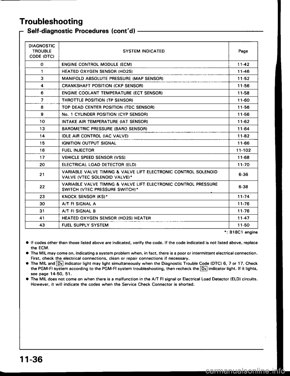
Self-diagnostic Procedures (cont'dl
':818C1 engine
a lf codes other than those listed above are indicated, verifv the code. lf the code indicated is not listed above, replace
rhe ECM.
a The MIL may come on, indicating a system problem when, in fact, there is a poor or intermittent electricalconnection.
First, check the electrical connections, clean or repair connections it necessary.
o The MIL and @ indicator light may light simultaneously when the Diagnostic Trouble Code (DTC) 6, 7 or 17. Check
the PGM-Fl system according to the PGM-Fl system troubleshooting, then recheck the l!! indicator light. ll it lights,
see page 14-5O, 51.
a The MIL does not come on when there is a malfunction in the A/T Fl signal or Electrical Load Detector (ELDI circuits.
However, it will indicate the codes when the Service Check Connector is shorted.
DIAGNOSTIC
TROUBLE
CODE (DTCISYSTEM INDICATEDPsge
oENGINE CONTROL MODULE IECM)11-42
,lHEATED OXYGEN SENSOR IHO25)1 1-46
aMANIFOLD ABSOLUTE PRESSURE {MAP SENSOR)11-52
4CRANKSHAFT POSITION (CKP SENSOR)1 1-56
oENGINE COOLANT TEMPERATURE (ECT SENSOR)11-58
THROTTLE POSITION (TP SENSOR}11-60
ITOP DEAD CENTER POSITION (TDC SENSORI1 1-56
9No. 1 CYLINDER POSITION (CYP SENSOR)1 1-56
10INTAKE AIR TEMPERATURE (IAT SENSOR)11-62
13BAROMETRIC PRESSURE (BARO SENSOR}1|-64
14IDLE AIR CONTROL (IAC VALVE}11-42
tcIGNITION OUTPUT SIGNAL11-66
toFUEL INJECTOR1't-102
17VEHICLE SPEED SENSOR {VSSI11-68
20ELECTRICAT LOAD DETECTOR (ELD)'t 1-70
21VARIABLE VALVE TIMING & VALVE LIFT ELECTRONIC CONTROL SOLENOID
VALVE {VTEC SOLENOID VALVE)'6-36
22VARIABLE VALVE TIMING & VALVE LIFT ELECTRONIC CONTROL PRESSURE
SWITCH (VTEC PRESSURE SWITCHI-6-38
23KNOCK SENSOR {KS}-11-7 4
30A/T FI SIGNAL A11-76
3'rA/T FI SIGNAL B1 1-76
4'lHEATED OXYGEN SENSOR (HO25} HEATER11-47
43FUEL SUPPLY SYSTEM1 1-50
11-36
Page 231 of 1413
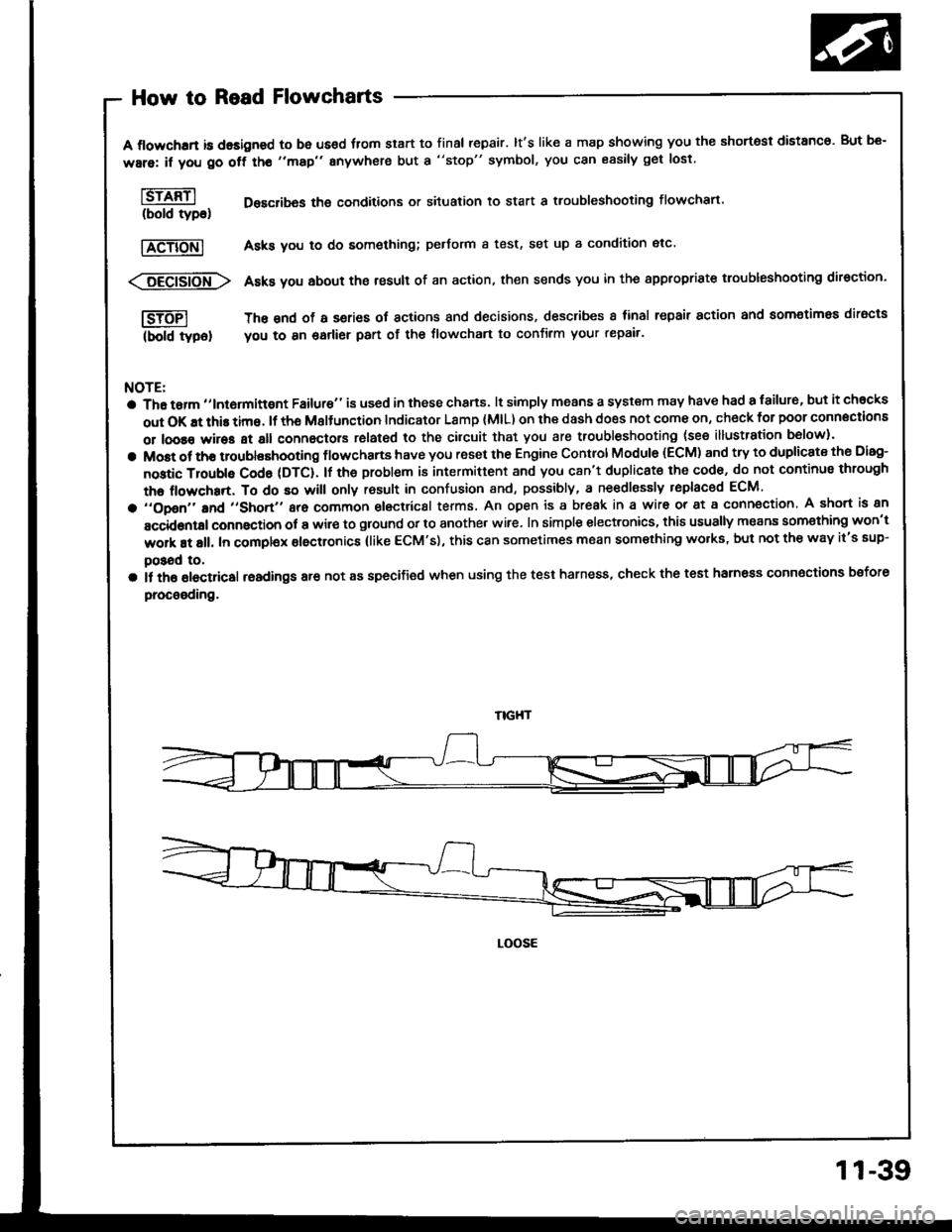
How to Read Flowcharts
A flowchrrt is dasigned to be us€d fiom start to final repair. lt's like a map showing you the shortest distanco. But be-
ware: if you go off tho "map" anywhere but a "stop" symbol, you can easily get lost
l6rffil Desclibas the conditions or situation to start a troubleshooting flowchart.(bold tyDo)
|TeTiONl Asks you to do something; pedorm a test, set up a condition etc'
<:6Eei6io-fr\> Asks you about the result of an action, then sends you in the appropriste troubleshooting direction.
I-SJTFI The snd of a series ot actions and decisions, describes I tinal repair action and aomotimea diracts
(bold typel you to 8n garlier part of the tlowchart to confirm your repair'
NOTE:
a Tha tarm ,,lntormittgnt Failure" is used in these chans. lt simply means a system may have had a failur6, but it chocks
out OK !t this time. lf th6 Msltunction Indicator Lamp (MlL) on ihe dash does not come on, check for poor connections
or loose wires at all connectors rolated to the cilcuit that you are troubleshooting (see illustration b6low).
a Most ot tho troublashooting flowchans have you reset the Engine Control Module (ECM) and try to duplicate the Disg-
nostic Troubls Cod6 (DTC). lf the problem is intermittent and you c8n't duplicat€ the cod6, do not continus through
the flowchart, To do so will only rosult in confusion and, possibly, a ne€dlessly replaced ECM
a ,,opon,'and ,,short,, are common electrical terms. An open is a break in a wir6 or at a conn€ction. A short is an
accidontal connaction ot a wir€ to ground or to another wire. In simple electronics, this usually means som€thing won't
work at all. In complex electronics (like ECM's), this can sometimes mean something wolks, but not the way it's sup-
poSad to,
a il th6 olectricsl readings are not as specified when using the test harness, check the test harness connoctions bsfore
procooding.
LOOSE
11-39
Page 233 of 1413
3. Fuel Cut-oft Control
a During deceleration with the throttle valve closed, current to the {uel injectors is cut otJ to improve fuel economy
at speeds over tollowing rpm:
. 8188l engine: 91O tpm (Canada model: 1,O50 rpm)
. 818C1 engine: 95O tpm (Canada model: l,O5O rpm)
a Fuel cut-olf action also takes place when engine speed exceeds, 7,O0O rpm {81 8B1 engine), 8,1O0 rpm (B 18Cl
engine), regardless oI the position of the throttle valve, to protect the engine from ovet-revving.
A/C Compressor Clutch Relay
When the ECM receives a domand for cooling trom the air conditioning system, it del8ys the compressor from being
enetgized, and enriches the mixture to assure smooth transition to the A/C mode.
Evaporative Emission (EVAP) Purge Control Solenoid Valve
When the engine coolant tempersture is below 163oF {73"C), the ECM supplies a ground to the EVAP pu.ge control
solenoid valve which cuts vacuum to the EVAP purge control diaphragm valve.
Intake Air Bypsss (lAB) Control Sol€noid Valve
When the engine rpm is below 5,750 rpm, the IAB control solenoid valve is activated by a signal from the ECM,
intske air flows through the long intake path, then high torque is delivered. At spaeds highe. than 5,750 rpm, the
solenoid valve is deactivated by the ECM, and intake air flows through the short intake path in order to reduce the
resistance in airflow.
ECM fail-safe/bEck-up Functions
1. Fail-sate Function
When an abnormality occurs in a signal from a sensor, the ECM ignores that signal and assumes a pre-progtammed
value tor that sensor that allows the engine to continue to run.
Back-uD Function
When an abnormalitv occurs in the ECM itself, the fuel iniectors are controlled by a back-up citcuit independent of
the system in order to permit minimal driving.
Self-diagnosis Function IMaltunction Indicator Lamp {MlL)1
Wh6n an abnormality occurs in a signal from a sensor, the ECM supplies ground for the MIL and stores the code
in erasable memory. When the ignition is initially turned on, the ECM supplies ground tor the MIL tor two seconds
to check the MIL bulb condition.
Two Trio Detection Method
To prevent tals€ indications, th€ Two Trip Dstection Method is used for the HO2S and fuel metering-related self-
diagnostic tunctions. When an abnormslity occurs, the ECM stores it in its memo.y. Wh€n the ssme sbnormality
recurs alter the ignition switch is turned OFF and ON ag8in, the ECM informs the driver by lighting the MlL.
However, to ease troubleshooting, this function is canc€ll€d when you short the service check connector. The MIL
will then blink immedistelv when an abnormality occurs.
4.
6.
2
4.
11-41