lock HONDA INTEGRA 1994 4.G Owners Manual
[x] Cancel search | Manufacturer: HONDA, Model Year: 1994, Model line: INTEGRA, Model: HONDA INTEGRA 1994 4.GPages: 1413, PDF Size: 37.94 MB
Page 411 of 1413
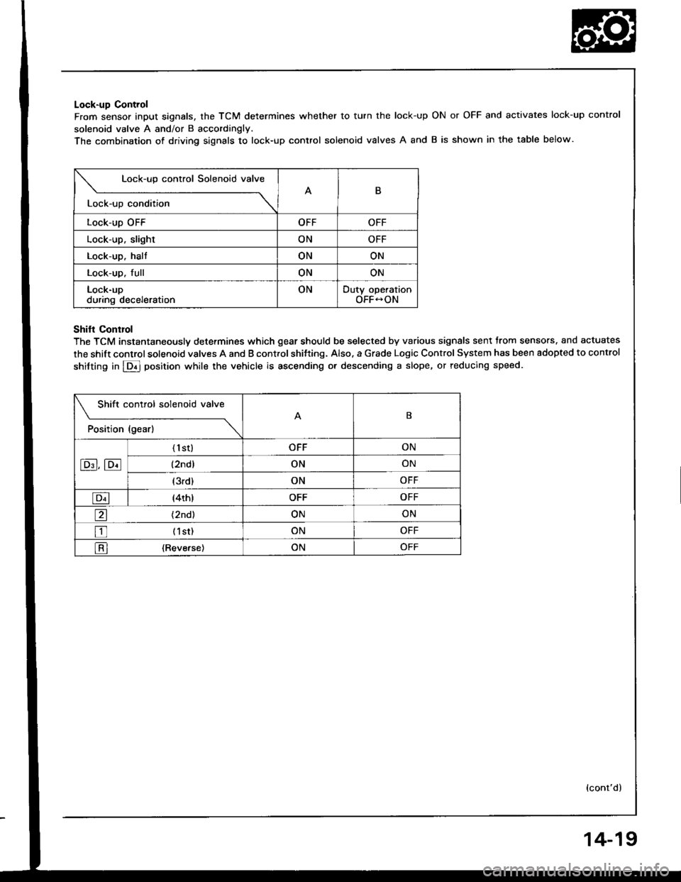
Lock-up Control
From sensor input signals, the TCM determines whether to turn the lock-up
solenoid valve A and/or B accordingly.
The combination of driving siqnals to lock-up control solenoid valves A and
ON or OFF and activates lock-up control
B is shown in the table below.
Lock-up control Solenoid valve
B
Lock-up condition \
Lock-up OFFOFFOFF
Lock-up, slightONOFF
Lock-up. haltONON
Lock-up. fullONON
Lock-upduring decelerationONDuty operationOFF-ON
Shifl Conrrol
The TCM instantaneously determines which gear should be selected by various signals sent trom sensors. and actuates
the shift control solenoid valves A and B control shitting. Also. a Grade Logic Control System has been adopted to control
shifting in E] position while the vehicle is ascending or descending a slope, or reducing speed.
Shift control solenoid valve
t"*b" ,t"-l
------\B
E,E
('l st)OFFON
(2ndlONON
(3rd)ONOFF
E(4th)OFFOFF
a(2nd)ONON
tr (lst)ONOFF
l-Rl {Reverse)ONOFF
(cont'd)
14-19
Page 413 of 1413
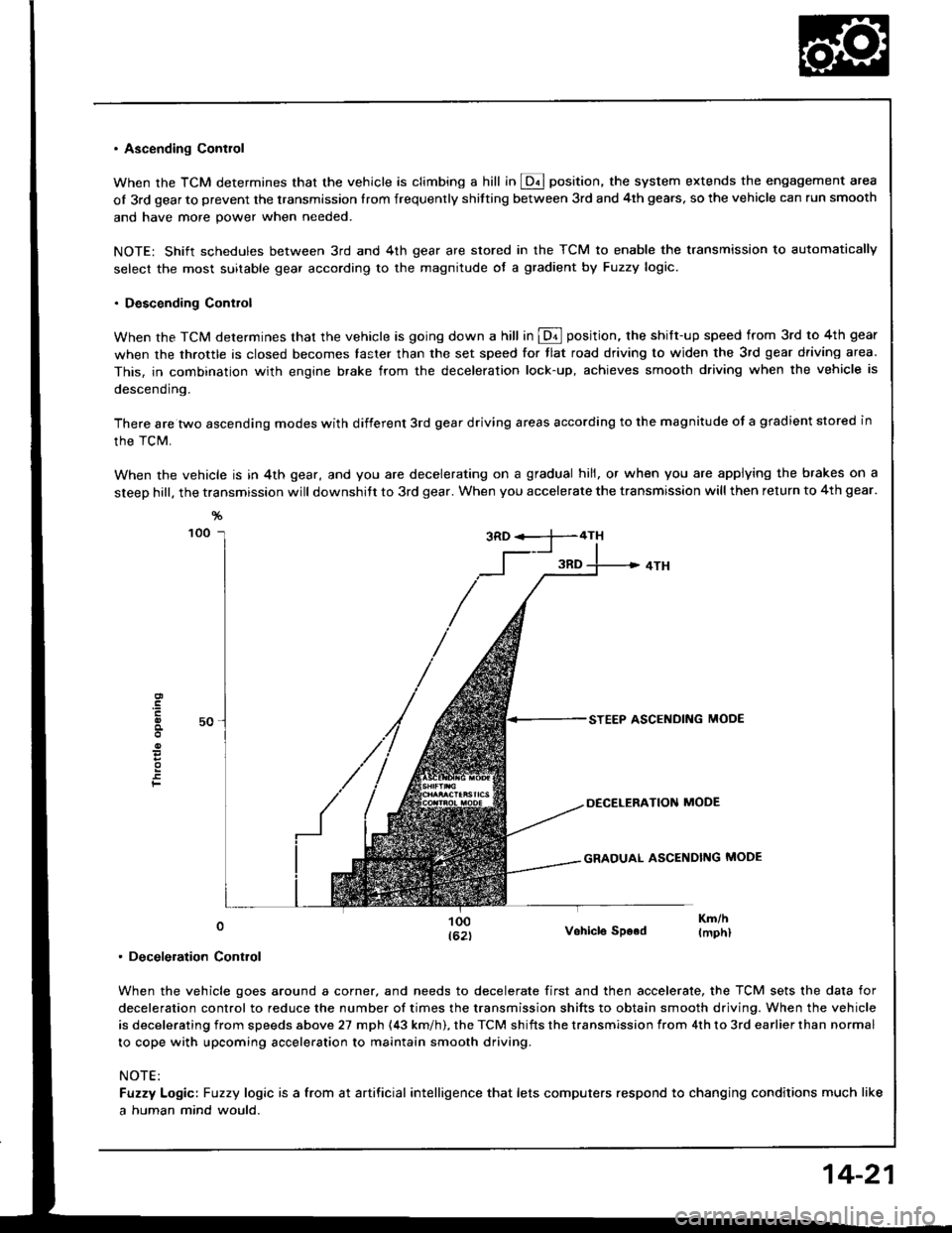
. Ascending Contlol
When the TCM determines that the vehicle is climbing a hill in @ position, the system extends the engagement area
of 3rd gear to prevent the transmission Irom frequenrly shitting between 3rd and 4th gears, so the vehicle can run smooth
and have more power when needed.
NOTE: Shift schedules between 3rd and 4th gear are stored in the TCM to enable the transmission to automatically
select the most suitable gear according to the magnitude of a gradient by Fuzzy logic.
. Descending Control
When the TCM determines that the vehicle is going down a hill in @ position. the shift-up speed from 3rd to 4th gear
when the throttle is closed becomes taster than the set speed for tlat road driving to widen the 3rd gear driving area.
This, in combination with engine brake from the deceleration lock-up, achieves smooth driving when the vehicle is
descending.
There are two ascending modes with different 3rd gear driving areas according to the magnitude of a gradient stored in
the TCM.
When the vehicle is in 4th gear, and you are decelerating on a gradual hill, or when you are applying the brakes on a
steep hill, the transmission will downshitt to 3rd gear. When you accelerate the transmission will then return to 4th gear.
F
0
. Deceleration Control
Vohicle SDood
When the vehicle goes around a corner, and needs to decelerate first and then accelerate, the TCM sets the data for
deceleration control to reduce the number of times the transmission shifts to obtain smooth driving. When the vehicle
is decelerating from speeds above 27 mph (43 km/h). the TCM shifts the transmission from 4th to 3rd earlier than normal
to cope with upcoming acceleration to maintain smooth driving.
NOTE:
Fuzzy Logic: Fuzzy logic is a from at artificial intelligence that lets computers respond to changing conditions much like
a human mind would.
14-21
Page 415 of 1413
Hydraulic Control
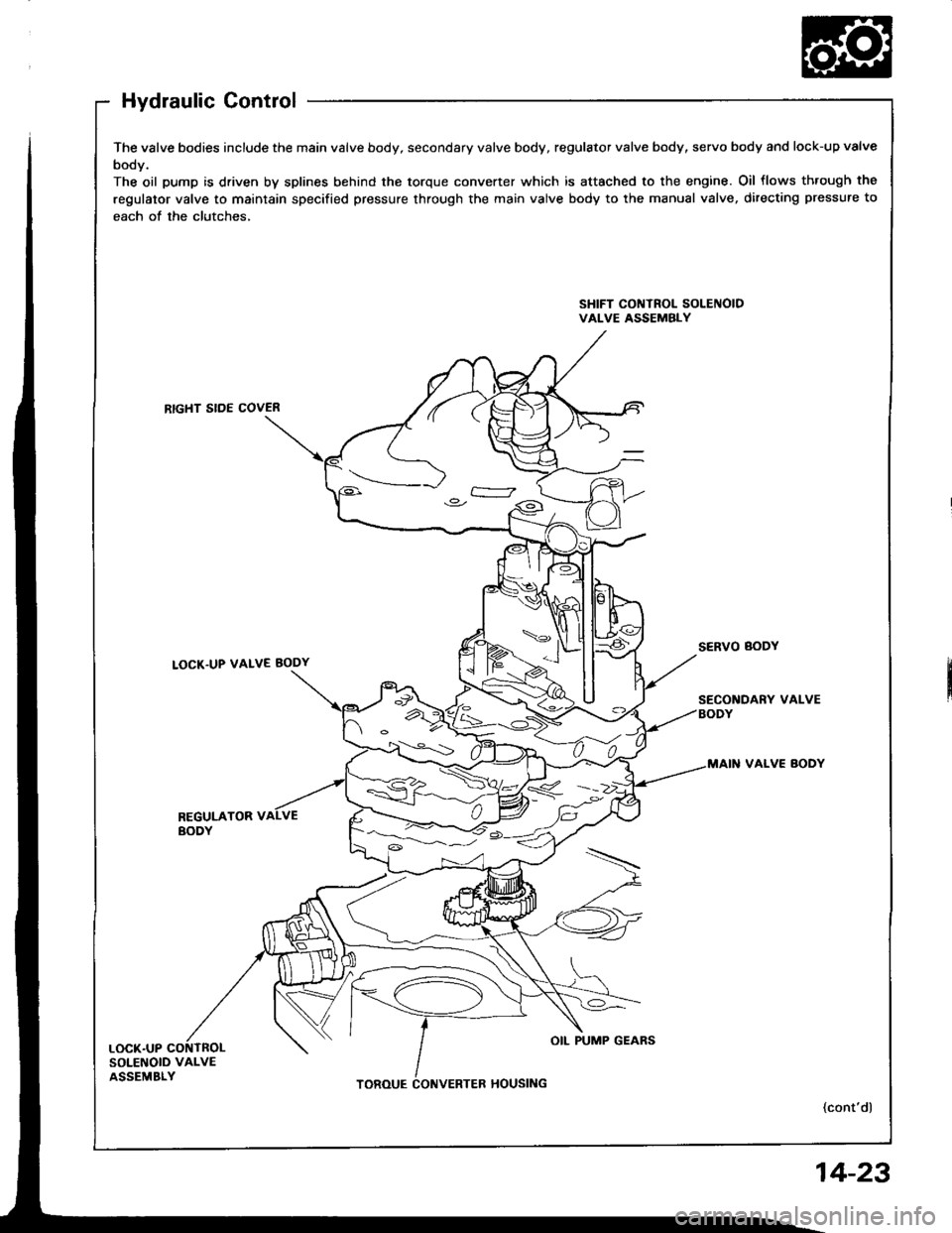
The valve bodies include the main valve body, secondary valve body, regulator valve body, servo body and lock-up valve
body.
The oil pump is driven by splines behind the torque converter which is attached to the engine. Oil flows th.ough the
regulator valve to maintain specified pressure through the main valve body to the manual valve, directing pressure to
each of the clutches,
SHIFT CONTROL SOLEIIOIDVALVE ASSEMBLY
RTGHT SIDE COVER
LOCK.UP VALVE BODY
VALVE BODY
REGULATOR VBODY
SOLENOID VALVEASSEMBLY
4<.__i: )o.-
OIL PUMP GEARS
14-23
Page 416 of 1413
Description
Hydraulic Control (cont'dl
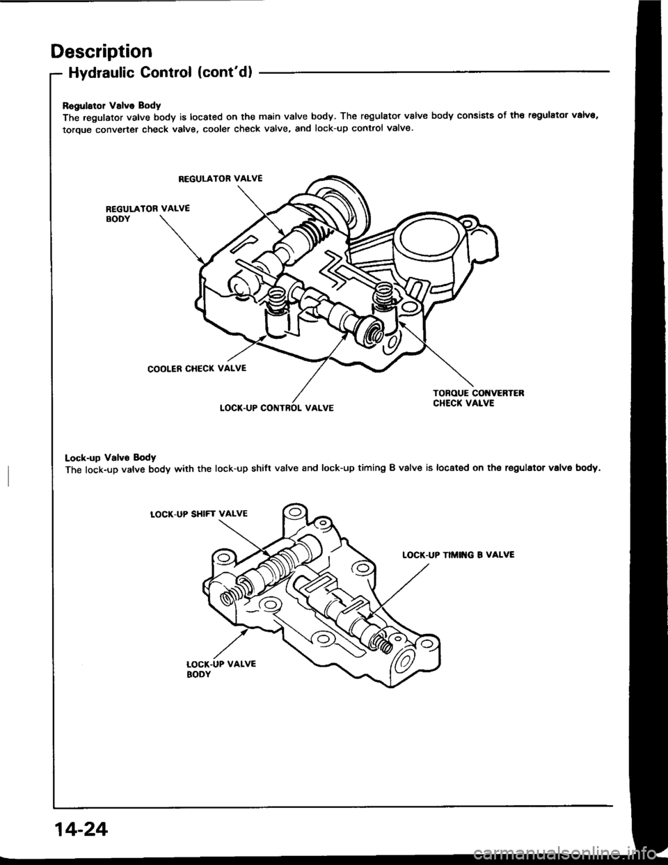
Ragularol Valve Body
The .egulator valve body is located on the main valve body. The regulator valve body consists of th€ regulator valva,
toroue converter check valve, cooler check valve, and lock-up contlol valve.
REGULATOR VALVE
REGULATOR VALVEBODY
COOLER CHECK VALVE
LOCT.UP CONTROI. VALVE
TONOUE COI{VERTEBCHECK VALVE
Lock-up Valvo Body
The lock-up valve body with the lock-up shilt valve and lock-up timing B valve is located on th€ regulator volvs body.
LOCK.UP SHIFT VALVE
TIMITG B VALVE
14-24
Page 421 of 1413
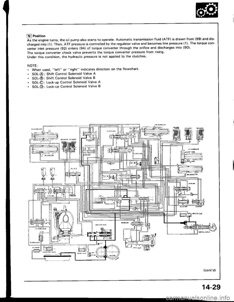
E Position
As the engine turns, the oil pump also starts to operate. Automatic transmission fluid (ATF) is drawn from (99) and dis-
charged into (1 ). Then, ATF pressure is controlled by the regulator valve and becomes line pressure ( 1 ). The torque con-
verter inlet pressure (92) enters (94) of torque converter through the orifice and discharges into {90}.
The torque converter check valve prevents the torque converter pressure from rising'
Under this condition, the hydraulic pressure is not applied to the clutches.
NOTE:. When used, "left" or "right" indicates direction on the llowchart
. SOL-@: Shift Control Solenoid Valve A
' SOL{D:Shift Control Solenoid Valve B
. SOL@: Lock-up Control Solenoid Valve A
. SOL-@: Lock-up Control Solenoid Valve B
(cont'd)
14-29
Page 422 of 1413
Description
Hydraulic Flow (cont'd)
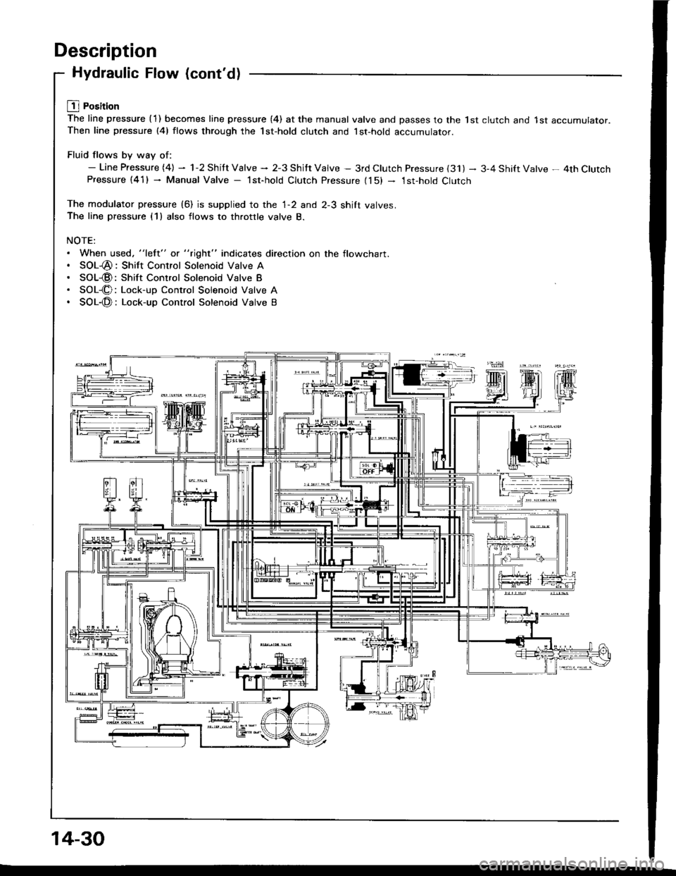
L1l Position
The line pressure {1) becomes line pressure (4) at the manual valve and passes to the lst clutch and 1st accumulator.Then line pressure (41 flows through the 1st-hold clutch and lst-hold accumulator.
Fluid flows by way of:- Line Pressure {4} - 1-2 Shitt Valve * 2-3 Shitt Valve - 3rd Clutch Pressure {31) - 3-4 Shift Valve - 4th ClutchPressure (41) - Manual Valve - lst-hold Clutch Pressure {15) - 1st-hold Clutch
The modulator pressure (6) is supplied to the 1-2 and 2-3 shift valves.The line pressure (1) also flows to throttle valve B.
NOTE:. When used. "left" or "right" indicates direction on the flowchart.. SOL-@: Shift Control Solenoid Valve A. SOL@: Shift Control Solenoid Valve B. SOL-@: Lock-up Control Solenoid Valve A. SOL-@: Lock-up Control Solenoid Valve B
14-30
Page 423 of 1413
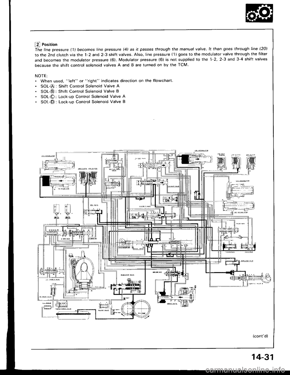
f4 Position
ihe line pressure (11 becomes line pressure (41 as it passes through the manual valve.lt then goes through line l2O)
to the 2nd clutch via the 1-2 and 2-3 shift valves. Also, line pressure (1 ) goes to the modulator valve through the filter
and becomes the modulator pressure (6). Modulator pressure (6) is not supplied to the 1-2, 2-3 and 3-4 shift valves
because the shitt control solenoid valves A and B are turned on by the TCM.
NOTE:. When used, "left" or "right" indicates direction on the flowchart
. SOL-@: Shift Control Solenoid Valve A
. SOL-@: Shilt Control Solenoid Valve B
. SOL-O: Lock-up Control Solenoid Valve A
. SOt -@ : Lock-up Control Solenoid Valve B
(cont'd)
14-31
Page 424 of 1413
Description
Hydraulic Flow (cont'dl
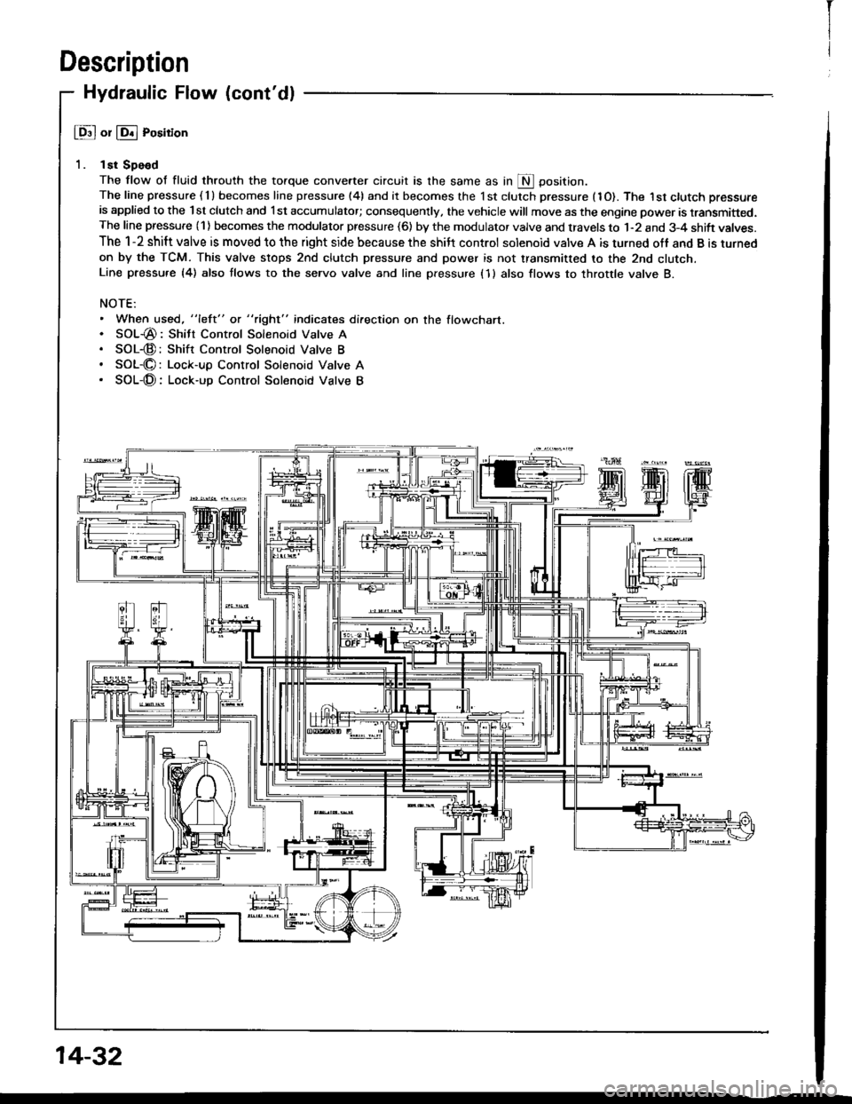
@ or @ Position
1. lst Spe€d
The flow of fluid throuth the torque convener circuit is the same as in S Oosition.The line pressure ( 1 ) becomes line pressure (4) and it becomes the 1 st clutch pressure (1O). The I st ctutch pressure
is applied to the lst clutch and l st accumulator; consequently, the vehicle will move as the engine power is transmitted.The line pressure (1) becomes the modulator pressure (6) by the modulator valve and travels to 1-2 and 3-4 shift valves.
The 1-2 shift valve is moved to the right side because the shilt control solenoid valve A is turned off and B is turned
on by the TCM. This valve stops 2nd clutch pressure and power is not transmitted to the 2nd clutcn.Line pressu.e {4) also tlows to the seryo valve and line pressure (1 } also flows to throttle valve B.
NOTE:. When used, "left" or "right" indicates direction on the flowchart.. SOL-@: Shitt Control Solenoid Valve A. SOL-@:Shift Control Solenoid Valve B. SOL-O: Lock-up Control Solenoid Valve A. SOL-@: Lock-up Control Solenoid Valve B
14-32
I
Page 425 of 1413
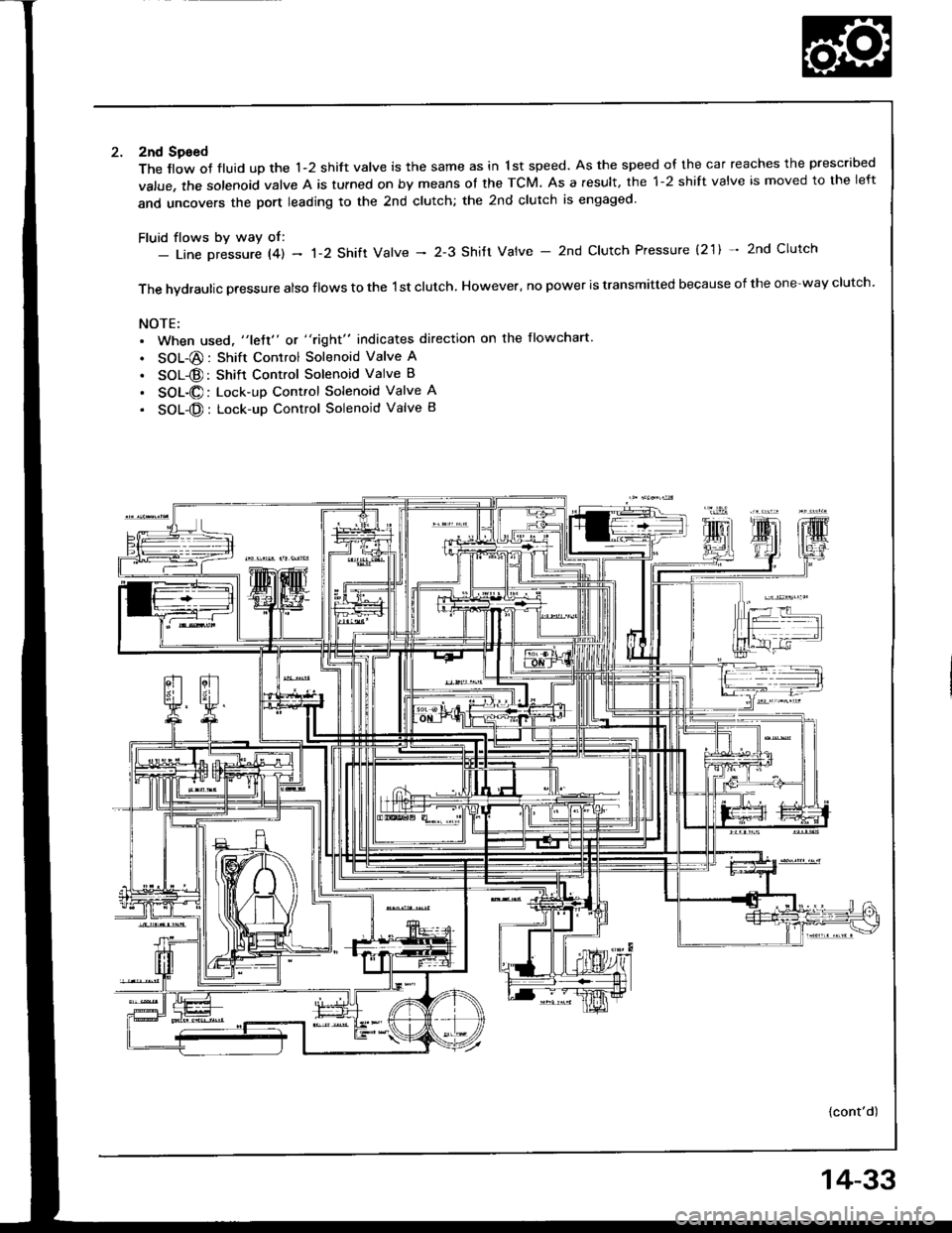
2nd Sgeed
The llow of fluid up the 1-2 shift valve is the same as in 1st speed. As the speed of the car reaches the prescribed
value, the solenoid valve A is tulned on by means ot the TCM. As a result, the 1-2 shift valve is moved to the left
and uncovers the port leading to the 2nd clutch; the 2nd clutch is engaged'
Fluid flows by way of:- Line Dressure l4l - 'l-2 Shift Valve - 2-3 Shitt Valve - 2nd Clutch Pressure (2'1) * 2nd Clutch
The hvdraulic pressure also flows to the 1st clutch, However, no power is transmitted because of the one-way clutch.
NOTE:. When used, "lett" or "right" indicates direction on the flowchart
. SOL-@: Shift Control Solenoid Valve A
. SOL@: Shift Control Solenoid Valve B
. SOL-@: Lock-up Control Solenoid Valve A
. SOL-@: Lock-up Control Solenoid Valve B
{cont'd)
14-33
Page 426 of 1413
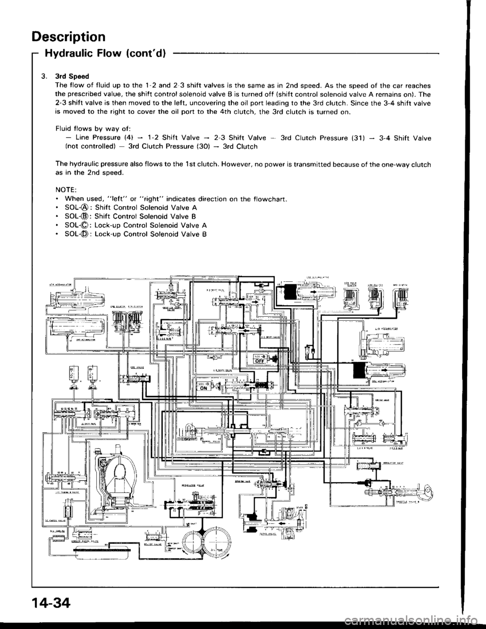
Description
Hydraulic Flow (cont'd)
3rd Speed
The tlow of fluid up to the 1-2 and 2 3 shift valves is the same as in 2nd speed. As the speed of the car reaches
the prescribed value, the shift control solenoid valve B is turned off {shilt control solenoid valve A remains on). The
2-3 shift valve is then moved to the left, uncovering the oil port leading to the 3rd clutch. Since the 3-4 shitt valve
is moved to the right to cover the oil port to the 4th clutch, the 3rd clutch is turned on.
Fluid tlows by way of:- Line pressure l4l - 1-2 shift valve - 23 Shift Valve * 3rd ctutch pressure (31) - 3-4 shift valve(not controlled) 3rd Clutch Pressure (3O) - 3rd Clutch
The hydraulic pressure also flows to the l st clutch. However, no power is transmitted because of the one-way clutchas in the 2nd speed.
NOTE:. When used, "lett" o( " tight" indicates direction on the flowcharl.. SOL-@: Shift Control Solenoid Valve A. SOL-@:Shift Control Solenoid Valve B. SOL-O: Lock-up Control Solenoid Valve A. SOL-@: Lock-up Control Solenoid Valve B
14-34