Cylinder HONDA INTEGRA 1994 4.G Workshop Manual
[x] Cancel search | Manufacturer: HONDA, Model Year: 1994, Model line: INTEGRA, Model: HONDA INTEGRA 1994 4.GPages: 1413, PDF Size: 37.94 MB
Page 1140 of 1413
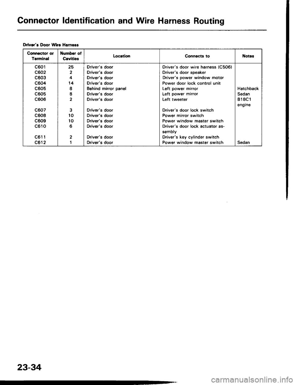
Connector ldentification and Wire Harness Routing
Drlvar's Door Wir6 Hamors
Connectot 01
Torminal
Number of
CavitlesLocationConnocts toNotos
c601
c602
c603
c604
c605
c605
c606
c607
c608
c609
c610
c61 1
c612
25
2
4
14
I
I
10
10
o
2
I
Driver's door
Driver's door
Driver's door
Driver's door
Behind mirror panel
Driver's door
Driver's door
Driver's door
Driv€r's door
Driver's door
Driver's door
Oriver's door
Driver's door
Oriver's door wire harness (C506)
Driver's door speaker
Driver's power window motor
Power door lock control unit
Left power mirror
Left power mirror
Lett tweeter
Driver's door lock switch
Power mirror switch
Power window master switch
D.iver's door lock actuator as-
sembly
Driver's key cylinder switch
Power window master switchSedan
Hatchback
Sedan
818C1
engrne
23-34
Page 1203 of 1413
Spark Plug Inspection
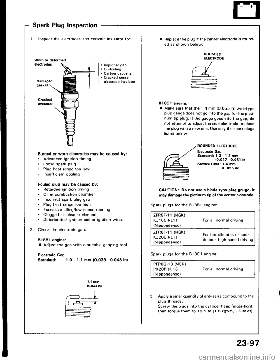
1. Inspect the electrodes and ceramic insulator for:
. rmproper gap. Oil-touling. Carbon deposits. Cracked centerelectrode insulatorDamagedgask6t
Burned or worn electlodes may be caused by:. Advanced ignition timing. Loose spark plug. Plug heat range too low. Insufficient cooling
Fouled plug may be caused by:. Retarded ignition timing. Oil in combustion chamber. lncorrect spark plug gap. Plug heat range too high. txcessive idling/low speed running. Clogged air cleaner element. Deteriorated ignition coil or ignition wires
Check the electrode gap.
Bl88l engine:
a Adjust the gap with a suitable gapping tool.
Electrode Gap
Standard: 1.0-1.1 mm (O.O39-0.O43 in)
1.1 mm{0.0,$ in)
Replace the plug if the center electrode is round-
ed as shown below:
ROUNDEDELECTROOE
Bl8Cl engine:
a Make sure that the '1.4 mm (0.055 in) wire-typeplug gauge does not go into the gap for the plati-
num tip plug. lf the gauge goes into the gap, do
not attempt to adjust the side electrode; replace
the plug with a new one. Use only the spark plugs
listed below.
ROUNDEO ELECTRODE
Electrode GapStandard: 1 .2-'l .3 mm{0.047 -O.051 in)Service Limit: 1.4 mm{0.055 in)
CAUTION: Do not use a blade-type plug gaugs, it
may damage the platinum tip of the center olectrodo.
Spark plugs for the 81881 engine:
Spark plugs for the B'l8Cl engine:
PFR6G_13 (NGK) IPK2OPR-113 I For all normal driving
{Nippondenso)
3. Apply a small quantity ol anti-seize compound to the
plug threads.
Screw the plugs into the cylinder head iingef-tight,
then torque them to 18 N.m (1.8 kgf.m, 13lbf.ft).
ZFRsF-1 1 (NGK)
KJl6CR-11 1
(Nippondenso)
For all normal driving
ZFR6F-1 1 (NGK)
KJ2OCR-11 1(Nippondenso)
For hot climates or con-
tinuous high speed driving
23-97
Page 1245 of 1413
Descraption
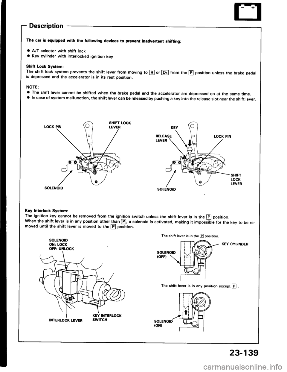
The car is squippod with thq following dovlc6. to prevont inadvoft.nt shitting:
a A/T selector with shift locka Key cylinder with interlocked ignition key
Shift Lock Syst6m;
The shitt lock system prevents the shift lever from moving to @ or lDil from the @ position unless the brake pedalis depressed and the accelerator is in its rest oosition.
NOTE:
a The shift lever cannot be shifted when the brake pedsl and the accelerator are depressed on at the same time.a In case ot system malfunction, the shift lever can be released by pushing a key into the release slot near the shift lever.
Koy Ints.lock Systsm:
The ignition key cannot be removed from the ignition switch unless the shil-t lever is in the E positionWhen the shift lever is in any position other than @, a sol€noid is activated, making it impossible for the key to be re-moved until the shift lever is moved to the llj position.
SOLEI{OIDON: LOCKOFF: UNLOCK
Th€ shift lever is in the E position.
KEY CYLINDER
The shift lever is in any position except pl .
II{TERLOCK LEVERswtTcH
23-139
Page 1339 of 1413
Power Door Locks
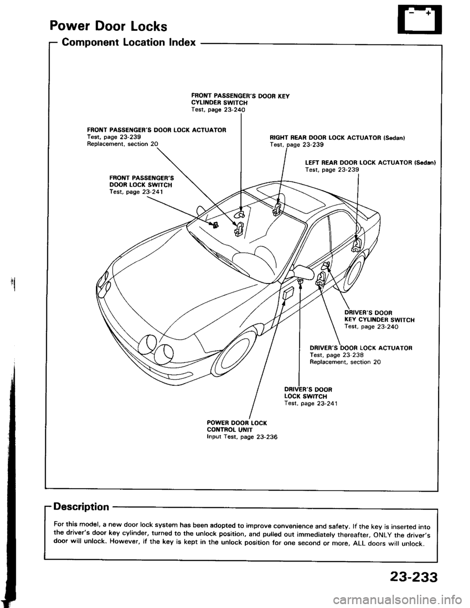
Component Location Index
1
FRONT PASSENGER'S DOOR LOCK ACTUATORTest. pago 23-239Reolacement. section 20
FRONT PASSENGER'SDOOR LOCK SWITCHfest, page 23-241
FRONT PASSENGER'S DOOR KEYCYLII{DER SWITCHTest, page 23-240
POWER OOOR LOCKCONTROL UNITfnput Tost, page 23-236
RIGHT REAR DOOR LOCK ACTUATOR lsodanlTest,
DOORKEY CYLINDER SWITCHTest. page 23-24O
DBIVER'S
DOOR
LOCK ACTUATORTest, page 23-238Roplacement, seclion 20
LOCK SWITCH'lest, page 23-241
Description
For this model, a new door lock system has been adopted to improve convenience and safety. lf the kev is insened intothe driver's door key cylinder, turned to the unlock position, and pulled out immediately thereafter, oNLy the driver.sdoor will unlock. However, if the key is kept in the unlock position tor one second or more, ALL doors wi
unlock.
23-239
LEFT REAR DOOR LOCK ACTUATOR {Sodan}Test, page 23-239
23-233
Page 1343 of 1413
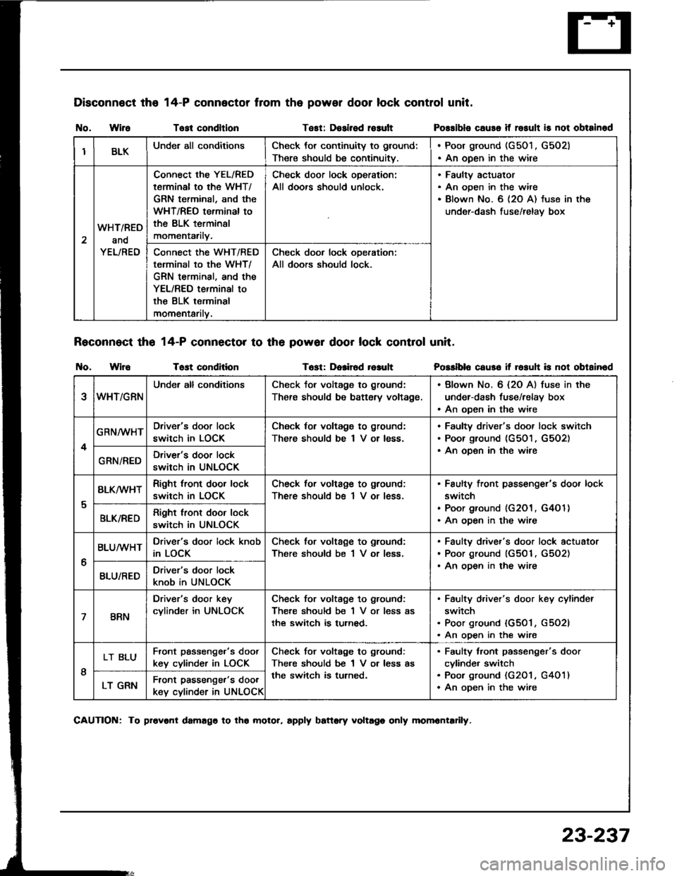
Disconnect the
I{o. WireTost condltlonTest: Dosirsd rosult
Reconnect tho 14-P connector to th6 powor door lock control unit.
t{o. WlroTost conditionTost: Dolir6d r6auh
14-P connector from the power door lock control unit.
Possibls cause if rosult is not obtainod
Posslblo caus6 it rosuh is not obtainod
IBLKUnder all conditionsCheck tor continuity to ground:
There should be continuitv.
. Poor ground (G501 , G502). An open in the wire
2
WHT/RED
and
YEL/RED
Connect the YEL/RED
tarminal to the WHT/
GRN terminal, and the
WHT/REO terminal to
the BLK terminsl
momentarily.
Check door lock oDeration:
All doors should unlock.
Faultv actuator
An open in the wire
Blown No. 6 (2O A) fuse in the
under-dash fuse/relav box
Connect the WHT/RED
terminal to the WHT/
GRN terminal, and the
YEL/RED terminal to
the BLK terminal
momentarilv.
Check door lock ooeration:
All doors should lock.
eWHT/GRN
Under all conditionsCheck tor voltage to ground:
There should be battsry voltage.
. Blown No. 6 {2O A) fuse in the
under-dash fuse/relay box. An open in the wire
4
GRN/WHTDriver's door lock
switch in LOCK
Check for voltagg to ground:
There should be I V or less.
Faultv driver's door lock switch
Poor ground (G501, G5O2)
An oDen in the wireGRN/REDDriver's door lock
switch in UNLOCK
I
BLK/wHTRight tront door lock
switch in LOCK
Check for voltage to ground;
There should bs 1 V or less.
Faulty front passenger's door lock
switch
Poor ground (G201, G4O 1)
An ooen in the wireBLK/REDRight lront door lock
switch in UNLOCK
6
BLUMHTDriver's door lock knob
in LOCK
Check for voltage to ground:
There should be 1 V or less.
Faulty driver's door lock actuator
Poor ground (G501, G5O2)
An ooen in the wireBLU/REDDriver's door lock
knob in UNLOCK
7BRN
Driver's door key
cylinder in UNLOCK
Check for voltage to ground:
There should be 1 V or less as
the switch is turned.
Faulty d,iver's door key cylinder
switch
Poor ground {G501, G5O2l
An open in the wire
I
LT BLUFront passenge.'s doot
key cylinder in LOCK
Check for voltage to ground:
There should be 1 V or less as
the switch is turned.
Faulty tront passenger's door
cylinde. switch
Poo. ground (G201 , G401)
An oDen in the wireLT GRNFront passenger's door
key cylinder in UNLOCK
CAUTION: To provonl damago to tho molor, rpply battory voltago only momrntadly.
23-237
Page 1346 of 1413
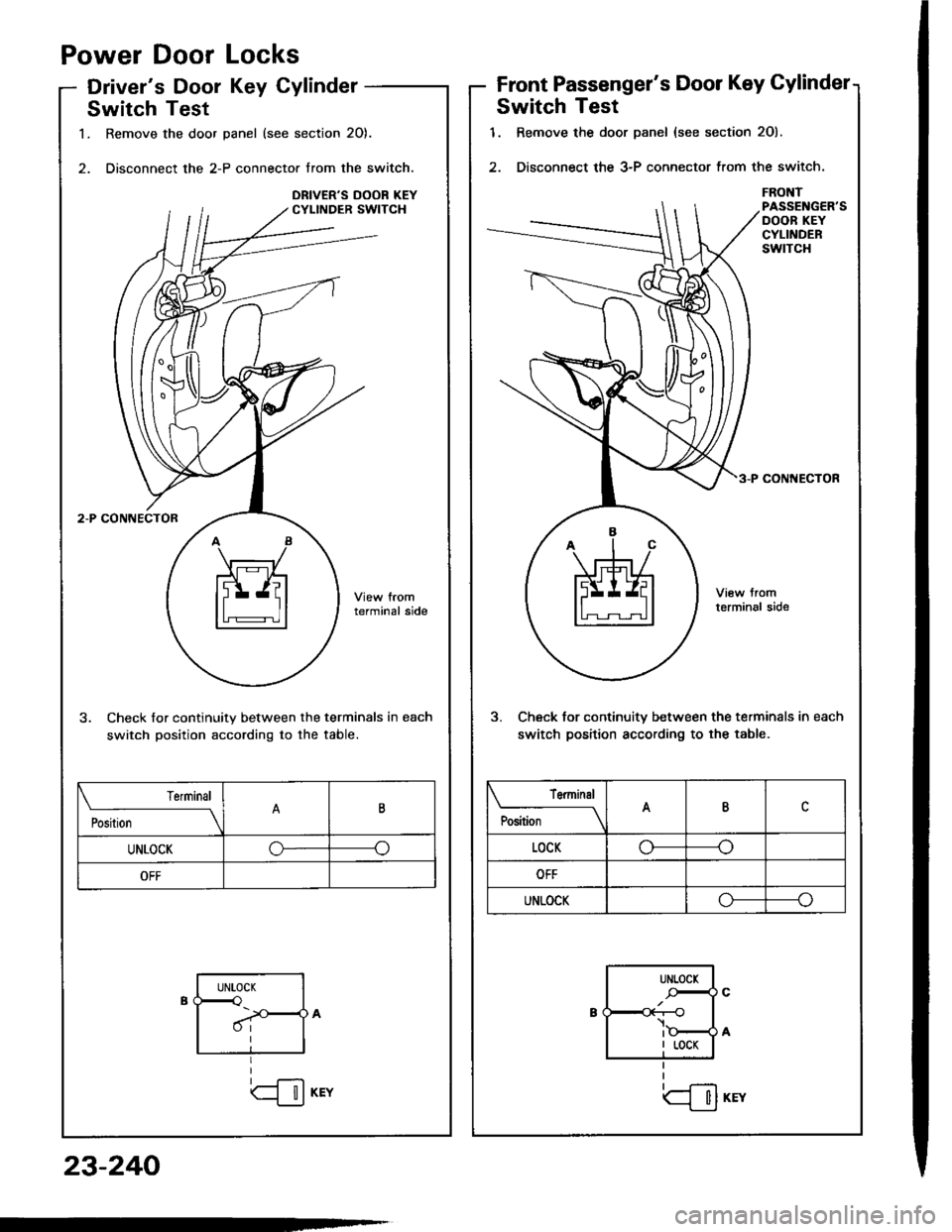
Power
Driver'
Door
s Dool
Locks
Key CylinderFront Passenger's Door Key Gylindet
Switch Test
1. Remove the door Danel {see section 2O).
2. Disconnect the 3-P connector trom the switch.
FRONTPASSENGER'SDOOB KEYCYLINDERswtTcH
coN ECIOR
3. Check tor continuitv between the terminals in each
switch position according to the table.
tfil*rr
Terminal
P""ft;---lABc
LOCKo----o
OFF
UNLOCKo----o
UNLOCK
-r--O
I LOCK
Switch Test
1. Remove the door panel (see section 20).
2. Disconnect the 2-P connector from the switch.
terminal side
3. Check for continuity between the terminals in each
switch position according to the table.
Position
TerminalB
UNLOCKGo
OFF
UNLOCK<
I
23-240