Cylinder HONDA INTEGRA 1994 4.G Workshop Manual
[x] Cancel search | Manufacturer: HONDA, Model Year: 1994, Model line: INTEGRA, Model: HONDA INTEGRA 1994 4.GPages: 1413, PDF Size: 37.94 MB
Page 665 of 1413
Steering Gearbox
Reassembly lcont'dl
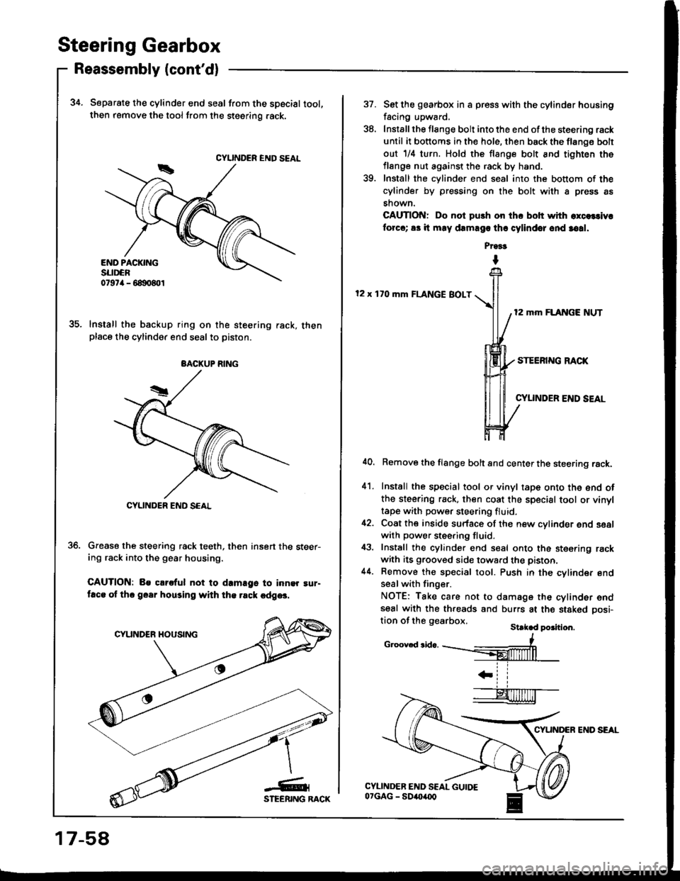
34. Separate the cylinder end seal from the spscial tool,then remove the tool from the steering .ack.
lnstall the backup ring on the steering rack, thenplace the cylinder end seal to piston.
Grease the steering rack teeth, then insert the steer-ing rack into the gear housing.
CAUTION: Be clrs{ul not to d.mage to inn9r !ur-ftca of thc goar housing with th€ rsck cdg6.
CYUNDER END SEAL
BACKUP RING
CYLINDER END SCAL
17-58
CYUNDER END SEAL
37.
'to
Set lhe gearbox in a press with the cylindor housing
facing upward.
Install the flange bolt into the end of the steering rack
until it bottoms in the hole, then back the flang€ bolt
out 1/il turn. Hold the flange bolt and tighten the
flange nut against the rack by hand.
Install the cylinder end seal into the bottom of the
cylinder by pressing on the bolt with a press as
shown.
CAUTION: Do not push on ihc bolt with excelcivr
forcc; 83 it may dEmago thr cylindor ond 3o!1.
Pr9!t
I
12 x 170 mm FLANGE BOLT
12 mm FLANGE NUT
STEERING RACK
CYUNDER END SEAL
41.
Remove the flange bolt and center the steering rack.
Install the special tool or vinyl tape onto the end ofthe steering rack, then coat the special tool or vinyltape with power steering fluid.
Coat the inside surface of the new cylinder end sealwith power steering fluid.
Install the cylinder end seal onto the ste€ring rackwith its grooved side toward the piston.
Remove the special tool. Push in the cylinder endseal with finger.
NOTE: Take care not to damage the cylinder endseal with the threads and burrs at the stakod oosi-tion of the gearbox.St k d po3ition.
c.oov.d3id...--#
IL ll
Page 666 of 1413
41.
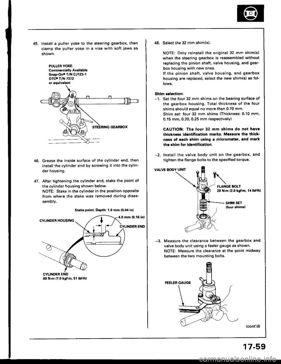
Install a puller yoke to the steering gearbox, then
clamp the puller yoke in a vise with soft jaws as
shown.
PULLER YOXE:Commcrcirlly AvrihbloSn.p-Ono T/N Cr123-lorco T/N 7372or aquivrlani
Grease the inside surface of the cylinder end, then
install the cylinder end by screwing it into the cylin-
der housing.
After tightening the cylinder end, stake the point of
the cylinder housing shown below.
NOTE: Stake in the cylinder in the position opposite
from where the stake was removed during disas-
semblv.
Strke point, D.pth: 1.0 mm (0.04 inl
4.0 mm 10.15 inlCYLINDER HOUSING
CYLINDER END
CYLINOER69 N.m 17.0 kgf.m, 51 lbtft)
,t8. Select the 32 mm shim(s).
NOTE: Only reinstall the original 32 mm shim(s)
when the steering gearbox is reassembled without
replacing the pinion shaft, valve housing, and gear-
box housing with new ones.
lf the pinion shaft, valve housing, and gearbox
housing are replaced, select the new shim{s) as fol-
rows.
Shim r€lection:-'1. Set the four 32 mm shims on the b€aring surface of
the gearbox housing. Total thickness of the four
shims should eoual no more than 0.70 mm.
Shim set: tour 32 mm shims (Thickness: 0.10 mm,
0.15 mm, 0.20, 0.25 mm respectivelyl
CAUTION: The tour 32 mm shimr do not hlva
thlckn$s idcntitication mukt. Mo!3ur. tho thicl-
oa33 of rach 3him using a miclomctrl, and mlrk
tho shim lor id6ntific8tion.
-2. Install the valve body unit on the gearbox, and
tighten the flange bolts to the specitied torque
VALVE BODY UNIT
FLANGE BOLT20 N.m {2.o kgtm, 14lbt'ftl
SHIM SET{foul thim.)
Measure the clearance between the gearbox and
valve body unit using a feeler gauge as shown.
NOTE: Measure the clearance at the point midway
between the two mounting bolts.
(cont'd)
17-59
Page 667 of 1413
Steering Gearbox
Reassembly lcont'd)
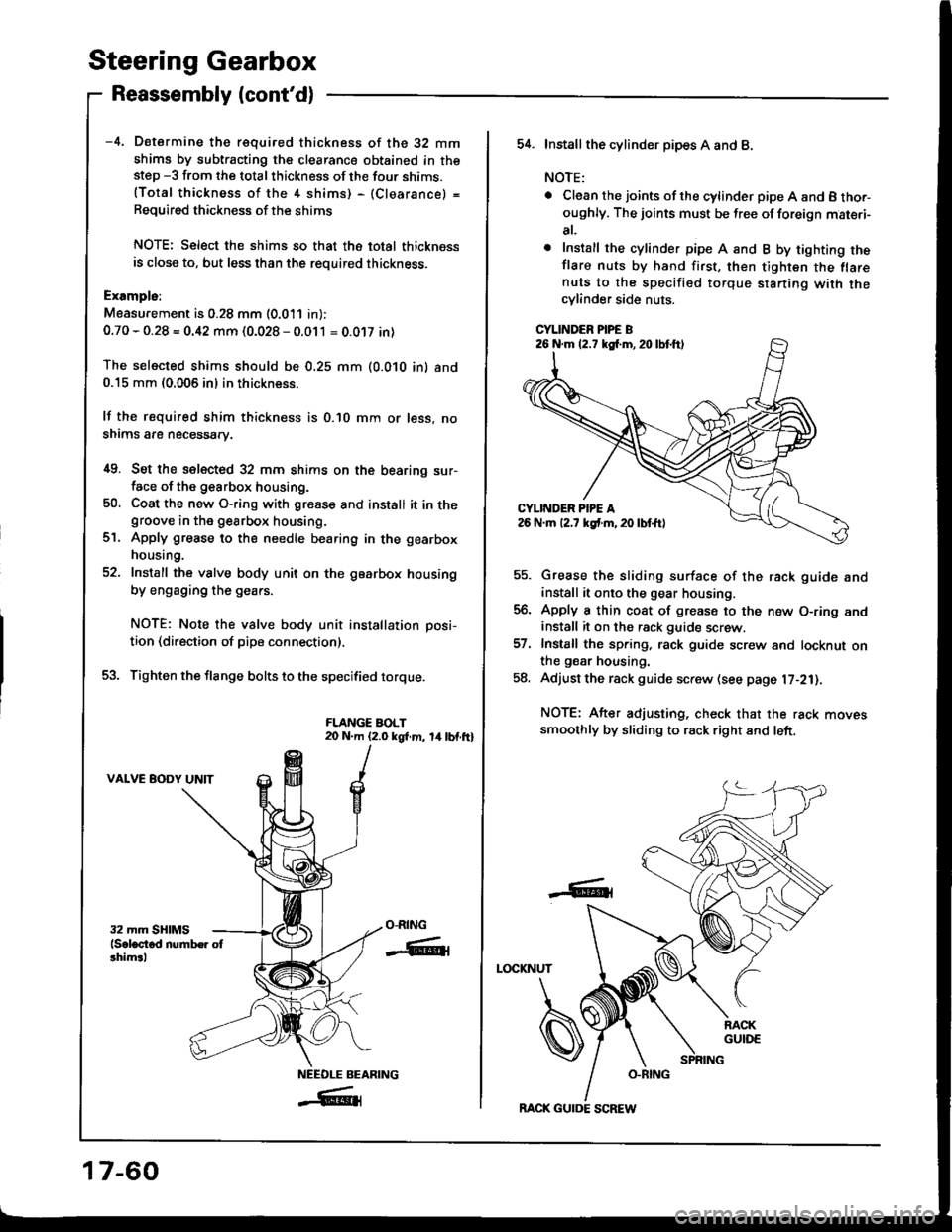
-4. Determine the requifed thickness of the 32 mm
shims by subtracting the clearance obtained in thestep -3 from the total thickness of the four shims.(Total thickness of the 4 shims) - (Clearance) =
Required thickness of the shims
NOTE: Select the shims so that th6 total thicknessis close to, but less than the required thickness.
Exampls:
Measu.ement is 0.28 mm (0.011 in):
0.70 - 0.28 = 0.42 mm (0.028 - 0.011 = 0.0't7 in)
The selected shims should be 0.25 mm (O.O1O in) and0.15 mm (0.005 in) in thickness.
lf the required shim thickness is 0.lO mm or less, no
shims are necessary.
i[9. Set the selected 32 mm shims on the bearing sur-face of the g€arbox housing.
50, Coat the new O-ring with gresse and install it in thegroove in the gearbox housing.
Apply grease to the needle bearing in the gearbox
housing.
Install the valve body unit on the gearbox housing
by engaging the gears.
NOTE: Note the valve body unit installation posi-
tion (direction of pipe connection).
Tighten the flange bolts to the specified torque.
FLANGE BOLT20 N.m (2.0 kgt m, 14lbf.ft)
VALVE BODY UNIT
ct.
O-RING
-ffiti
NEEOLE BEARING
_#{
17-60
BACK GUIDE SCREW
54. Installthe cylind6r pipes A and B.
NOTE:
. Clean the joints ofthe cylinder pipe A and B tho.-oughly. The joints must be free of foreign mat€.i-
at,
o Install the cylinder pipe A and B by tighting theflare nuts by hand first, then tighten the flarenuts to the specified torque starting with thecylinder side nuts.
CYLINDER PIPE B
Grease the sliding surface of the rack guide andinstall it onto the gear housing.
Apply a thin coat of grease to the n€w O-ring andinstall it on the rack guide screw.
Install the spring, rack guide screw and locknut onthe gear housing.
Adjust the rack guide screw (see page l7-21).
NOTE: After adjusting, check that the rack movessmoothly by sliding to rack right and left.
LOCKNUT
-6t
26 N.m (2.7 kg{.m,20lbtft)
Page 669 of 1413
Steering Gearbox
Reassembly (cont'dl
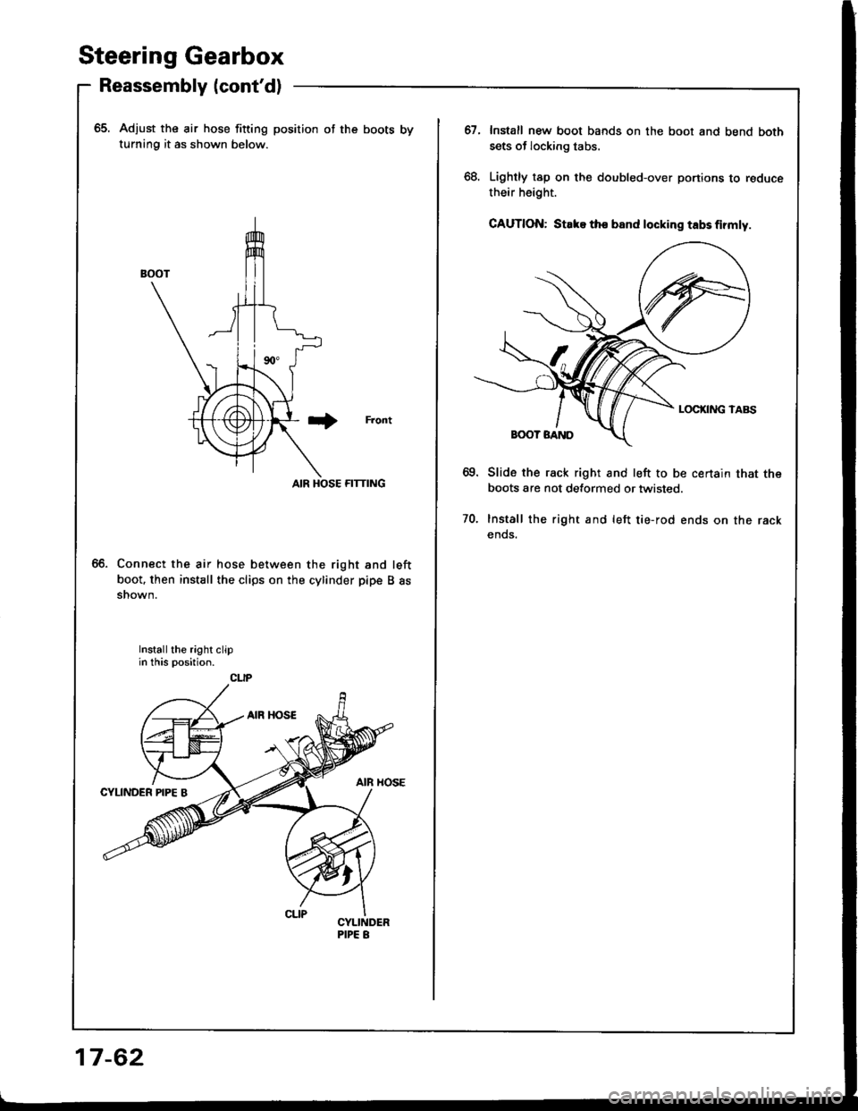
65. Adjust the air hose fitting position of the boots by
turning it as shown below.
Front
AIR HOSE FITTING
Connect the air hose between the right and left
boot. then install the clips on the cylinder pipe B assnown.
Install the right clipin this position.
CLIP
17-62
67.Install new boot bands on the boot and bend both
sets of locking tabs.
Lightly tap on the doubled-over portions to reduce
their height.
GAUTION: Stake tho band locking tabs firmly.
Slide the rack right and left to be certain that the
boots are not detormed or twisted.
Install the right and left tie-rod ends on the rack
ends.
70.
Page 979 of 1413
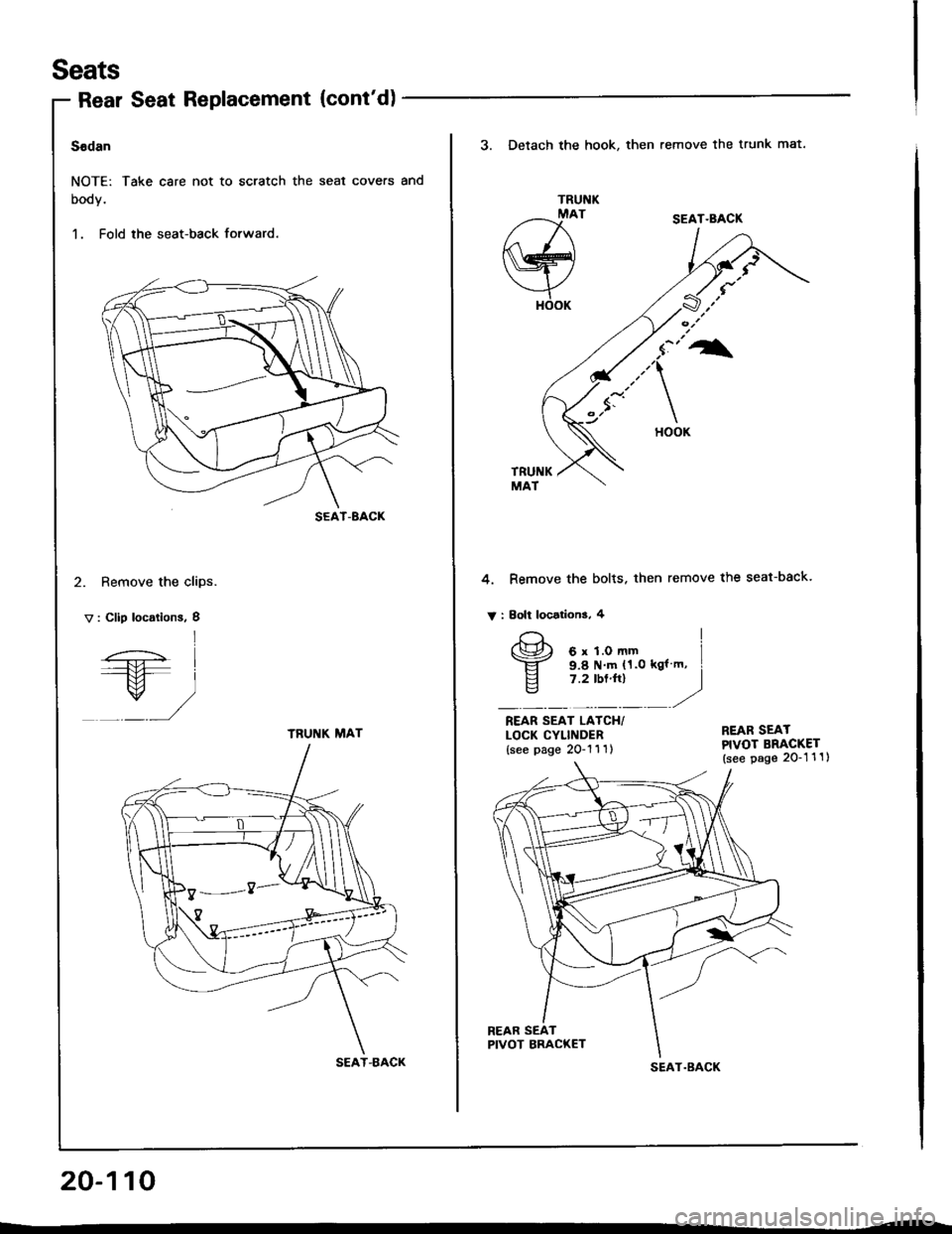
Seats
Rear Seat Replacement (cont'd)
Sedan
NOTE: Take care not to scratch the seal covers and
booy.
1. Fold the seat-back forward.
2. Remove the clips.
V : Clip locations, I
SEAT-8ACK
l
/-.;- I----+tl l---M- I
/ /,/
TRUNK MAT
SEAT-BACK
20-110
3. Detach the hook, then remove the trunk mat.
TRUNKMAT
a-^I{ \
Nry
YHOOK
SEAT.BACK
TRUNKMAT
4. Remove the bolts. then remove the seat-back.
V : Eolt locations, 4
REAR SEAT LAICH/LOCK CYLINDER{see page 2O-'l 1 1l
REAR SEATPIVOT BRACKET(see page 2O-1 1 1)
REAR SEATPIVOT BRACKET
I
I gel?"Til.*,,", i
E 7.2 tbt'trl I" -----r"
SEAT.BACK
Page 980 of 1413
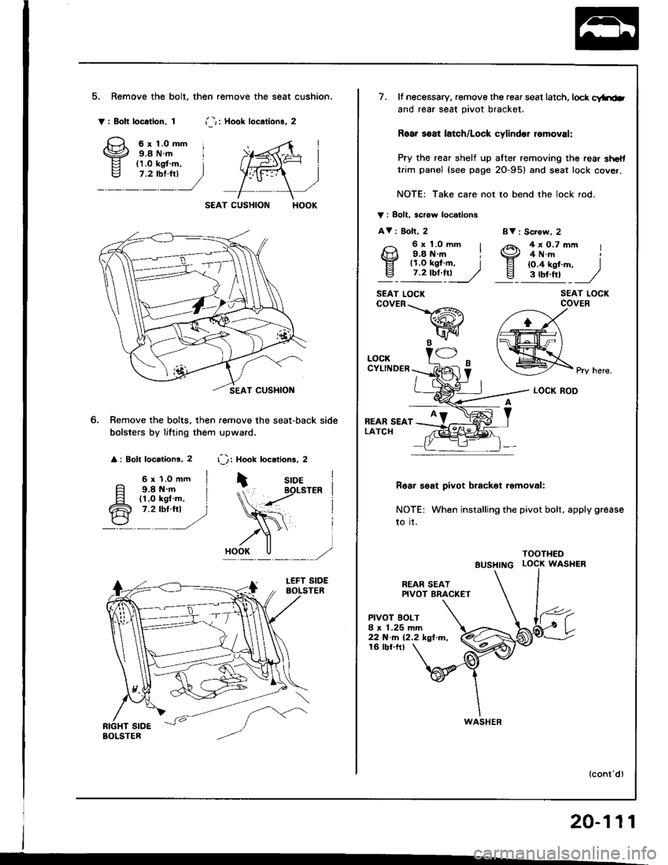
5. Remove the bolt, then .emove the seat cushion.
Y: Bolt location. 1i -r i Hool loc.lion3. 2
6r1.0mm i9.8 N.m I
SEAT CUSHION
Remove the bolts, then remove the seat-back side
bolsters by lifting them upward.
: Bolt locationr, 2 r'): Hook locetions, 2
6 r 1.o mm I9.8 N.m i(1.0 kgl'm, I7.2 tbt.fti )
BV : Sc?ow, 2
SEAT LOCKCOVER
Pry here.
LOCK ROD
R6ar seat pivot brackol removal:
NOTE: When installing the pivot bolt, apply grease
to it.
TOOTHED
BUSHTNG LOCK WASHER
REAR SEATPIVOT BRAC(ET
PIVOT BOLT8 x 1.25 mm22 N.m (2.2 kgf m,16 tbf.ftt
20-111
7. lf necessary, remove the rear seat latch, lock c!ftiab
and rear seat pivot bracket.
Roar soat latch/Lock cylinder r€moval:
Pry the rear shelj up after removing the rear shelttrim panel (see page 2O-95) and seat lock cover.
NOTE: Take care not to bend the lock rod.
V i Bolt. scrow locations
AV i Boll, 2
9: l;o--' I4x0.7mm I4 N.rrt
EI lr.o tgf .m, Iv_ 7.2 tbf.ft!____//
9.8 tt.m il1.O kgf.m, I{O.4 kgf'm, )3tbt.ttt J
SEAT LOCKcovER\-_L/-R\
wB -"1/ -
LOCKCYLINDER
REAR SEATLATCH
WASHER
Page 1024 of 1413
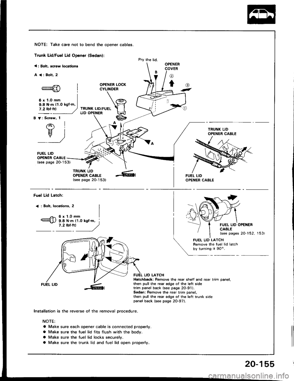
NOTE: Take care not to bend the opener cables.
Trunk Lid/Fuel Lid Oponer {Sodan}:
< : Bolt, scrow locatlon!
A<:Bolr,2
OPENER LOCKCYLINDER
TRUNK LID/FUELLID OPENER
B V: Scrow, 1
AI-}{- IH. I
_:_)
FUEL LID
Pry the ljd.OPENERCOVER
o
to-*rr*@
6 r 1.0 mm
()t
OP€NER CABLE(seo page 2O-153)
TRUNK LIDOPENER CABLE(see page 20-1 53)
9.8 N m 11.O kgl m,
Fuol Lid Lstch:
< : Boh, locotions, 2
6r1.0mm
FUEL LID OP€NERCAALE(see pages 20-152, 153)
9.8 N m 11.0 ksl'm, i7 '2 tbt'''l
------,//
FUEL LID
lnstallation is the reverse of the removal orocedure.
NOTE:
a Make sure each opener cable is connected properly.
a Make sure the fuel lid fits flush with the body.
a Make sure the tuel lid locks securelv.
a Make sure the trunk lid and fuel lid open properly.
LIO LATCHHatchbock: Remove the rear shelf and rear trim oanel.then pull the rear edge ot the lett sidetrim panel back (soe page 2O-91).Sodan: Remove the rear trim panel,then pull the rear edge of the left trunk sidepanel back {see page 2O-971.
FUEL LIO LATCHRemove the fuel lid latchby turning it 90o.
20-155
Page 1025 of 1413
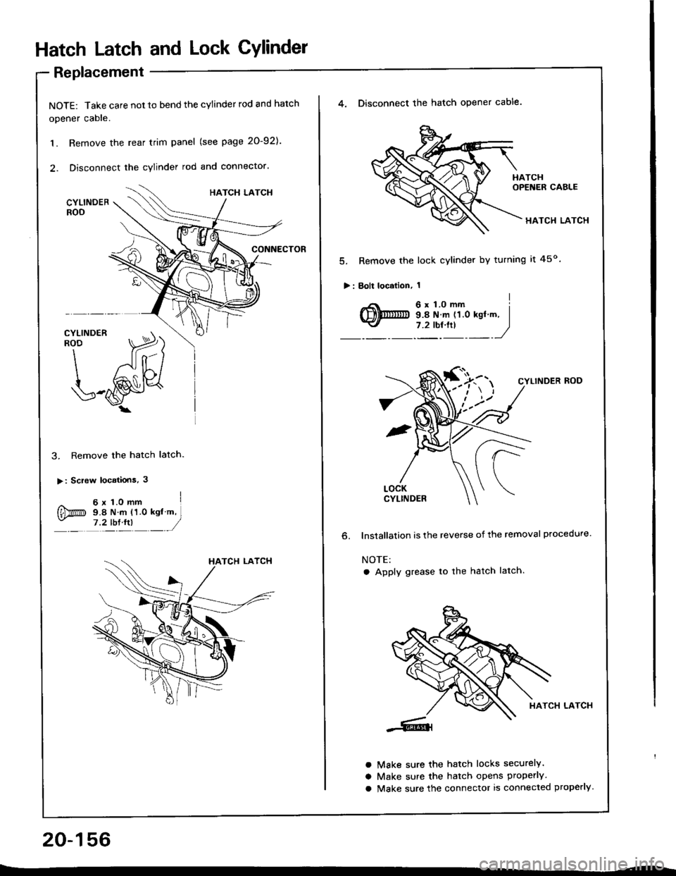
Hatch Latch and Lock CYlindet
Replacement
NOTE: Take care not 10 bend the cylinder rod and hatch
opener cable.
1. Remove the rear trim panel (see page 20-921.
2. Disconnect the cylinder rod and connector.
3. Remove the hatch latch.
>: Screw locatiois, 3
^ 6x1.omm I
{Dm s.e N m (1.0 ksl m,- ,?tb:tn __/
20-156
4. Disconnect the hatch opener cable.
HATCH LATCH
5. Remove the lock cylinder by turning it 45o
>: Bolt localion, 1
o.
CYLINDER ROD
lnstallalion is the reverse of the removal procedure.
NOTE:
a Apply grease to the hatch latch.
HATCH LATCH
Make sure the hatch locks securely.
Make sure the hatch opens properly.
Make sure the connector is connected properly.
a
a
a
Page 1026 of 1413
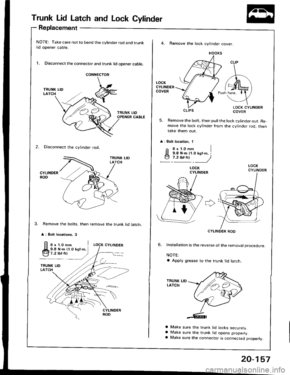
Trunk Lid Latch and Lock Cylinder
Replacement
NOTE: Take care not to bend the cylinder rod and trunklid opener cable.
l. Disconnect the connector and trunk lid opener cable.
CONNECTOR
2. Disconnect the cylinder rod.
CYLINDERROD
Remove the bolts, then remove the trunk lid latch.
A : Bolt locations, 3
LIDCABLE
4. Remove the lock cylinder cover.
HOOKS
LOCK CYLINDERCOVER
5. Remove the bolt, then pull the lock cylinder out. Re,move the lock cylinder trom the cylinder rod, thentake them out.
: Bolt location, 'l
CLIP
CLIPS
F 6xl.Omm I
q;i!!"jy
LOCKCYLINDER
CYLINDER ROD
6. Installation is the reverse ol the removat proceoure.
NOTE:
a Apply grease to the trunk lid latch,
a Make sure the trunk lid locks securelV.a Make sure the trunk lid opens properly.a Make sure the connector is connected properly.
/ ./,.,
,/'e4
20-157
Page 1122 of 1413
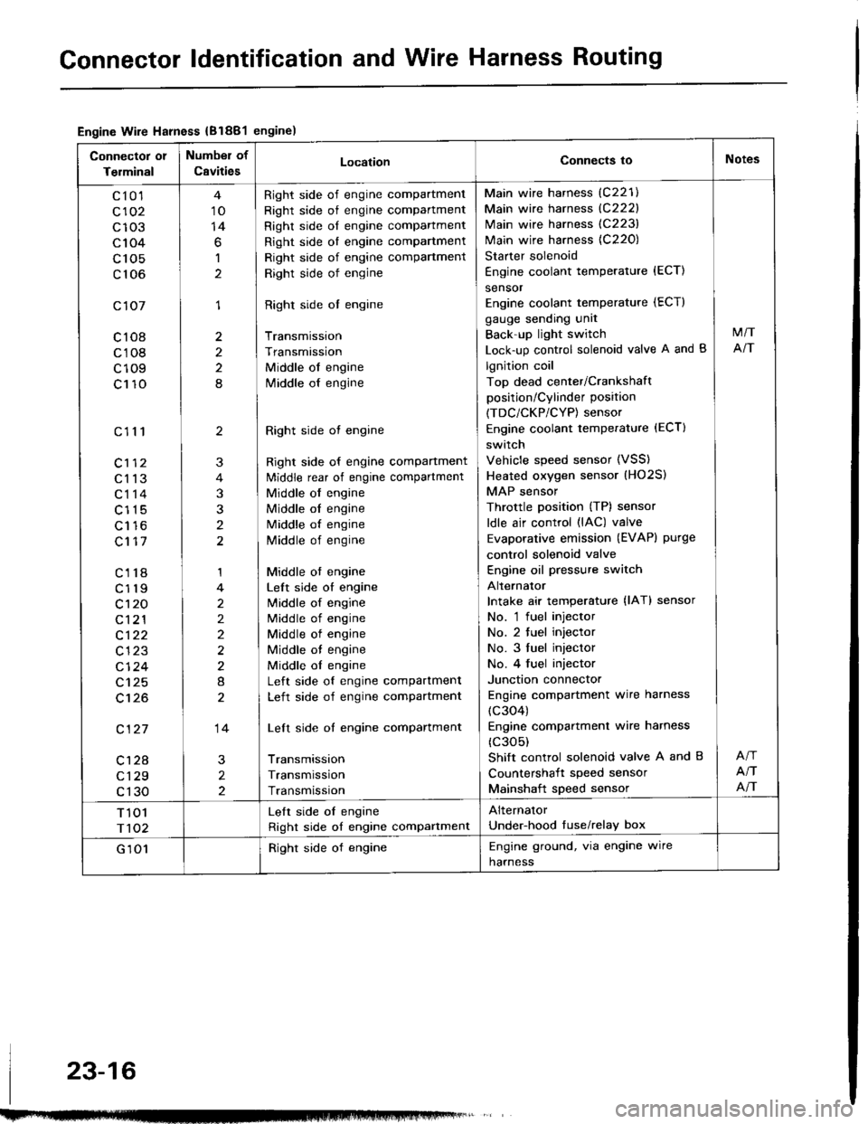
Gonnector ldentification and Wire Harness Routing
Engine Wire Harness {B1881engine)
Connector 01
Terminal
Number of
CavitiesLocationConnects ioNotes
c10'l
c102
c103
c104
c 105
c106
c107
c108
c108
c109
c110
c111
c113
c114
c115
Lt to
c117
c118
c119
c't 20
c121
c122
c123
cl24
c125
c't26
c127
c128
c129
c130
10
14
6
1
1
2
2
8
2
3
t
1
2
2)
2
8
14
2
2
Right side of engine compartment
Right side of engine compartment
Right side of engine compartment
Right side ol engine compartment
Right side of engine compartment
Right side of engine
Right side ol engine
Transmission
Transmission
Middle of engine
lvliddle of engine
Right side ot engine
Right side of engine compartment
ldiddle rear of engine compartment
Middle of engine
Middle ol engine
Middle of engine
Middle of engine
Middle ot engine
Left side of engine
lvliddle of engine
Middle of engine
Middle of engine
Middle ot engine
Middle ol engine
Left side of engine compartment
Left side of engine compartment
Left side of engine compartment
Transmission
Transmission
Transmission
Main wire harness (C221)
Main wire harness {C222}
Main wire harness (C223)
Main wire harness {C220)
Starter solenoid
Engine coolant temperature {ECT)
sensor
Engine coolant temperature (ECT)
gauge sending unit
Back'up light switch
Lock-up control solenoid valve A and B
lgnition coil
Top dead center/Crankshaft
position/Cylinder position
(TDC/CKP/CYP) sensor
Engine coolant temperature (ECT)
switch
Vehicle speed sensor (VSS)
Heated oxygen sensor (HO2S)
MAP sensor
Throttle position (TP) sensor
ldle air control (lAC) valve
Evaporative emission (EVAPI purge
control solenoid valve
Engine oil pressure switch
Alternator
Intake air temperature {lAT} sensor
No. 'l fuel injector
No. 2 tuel injector
No. 3 fuel injector
No. 4 fuel injector
Junction connector
Engine compartment wire harness
(c304)
Engine compartmenl wire harness
(c305)
Shift control solenoid valve A and B
Countershait speed sensor
Mainshaft speed sensor
M/T
NT
NT
NT
T 101
r102
Lelt side oI engine
Right side of engine compartment
Alternator
Under-hood tuse/relay box
G 101Right side of engineEngine ground, via engine wire
harness
23-16