section 23 HONDA INTEGRA 1994 4.G Workshop Manual
[x] Cancel search | Manufacturer: HONDA, Model Year: 1994, Model line: INTEGRA, Model: HONDA INTEGRA 1994 4.GPages: 1413, PDF Size: 37.94 MB
Page 1308 of 1413
Horn
SwitchTest(cont'd)
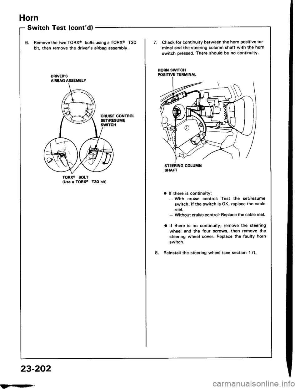
6.Remove the two TORX@ bolt6 using a TORX@ T30
bit, then remove the driver's airbag assembly.
Check for continuity between the horn positive ter-
minal and the steering column shaft with the horn
switch pressed, There should be no continuity.
HORN SwlTCHPOSITIVE TERMIITAL
TORXO BOLT(U!6 s TORxo T3O bitl
8.
a lf there is continuitv:- With cruise control: Test the set/resume
switch. lJ the switch is OK, replace the cable
reel.- Without cluise control: Replace the cable reel.
a lJ there is no continuity. remove the steering
wheel and the four screws, then remove the
steering wheel cover. Replace the faulty horn
switch.
Reinstall the steering wheel {see section 17).
DB|vEN'SAIRBAG ASSEMBLY
23-202
ilFrrI|qFrl"
Page 1316 of 1413

Rear Window Defogger
Function Test
CAUTION: Be carelul not to scratch 01 damago ths
defogger wires with th€ tsster probe.
1 . Check for voltage between the positive terminal and
body ground with the ignition switch and the delog-
ger switch ON. There should be battery voltage.
a lf there is no voltage, check for
- laulty detogger relay.- faulty defogger switch.- faulty integrated control unit.- an open in the BLK/GRN wire
a lJ there is baftery voltage, go to step 2.
NEGATIVE TERMIiIALPOSITIVE TERMINAL
Turn the rear window detogger switch OFF, Check
for continuity between the negative terminal and
body ground.
a It there is no continuity, check to. an open in the
defogger ground wire.
a ll there is continuity, go to step 3.
Touch the voltmeter positive lead to the halfway
point of each defogger wire, and the negative lead
to the negative terminal.
There should be apptoximately 6 V with the ignition
switch and defogger switch ON.
a lf the voltage is as specified, the defogger wire
is OK.
a lf the voltage is not as specified. repai, the defog-
ger wire:
lf it is more than 6 V, look for the damage on
the negative half on the grid.
- lf it is less than 6 V. iook for the damage on
the positive half of the grid.
Defogger Wires Repair
NOTE: To make an eftective repair. the broken section
must be no longer than one inch.
1 . Lightly rub the area around the break with line steel
wool, then clean it with alcohol.
2. Carefullv mask above and below the broken portion
of the defogger wire with cellophane tape.
Using a small brush, apply a heavy coat of silver con-
ductive paint extending about 3 mm ( 1/8 inl on both
sides of the break. Allow 30 minutes to dry.
NOTE: Thoroughly mix the paint before use.
Check for continuity in the repaired wire.
Apply a second coat of paint in the same way.
it drv three hours betore removing the tape.
4.
OPEN
23-210
tLet
Page 1317 of 1413
Moonroof
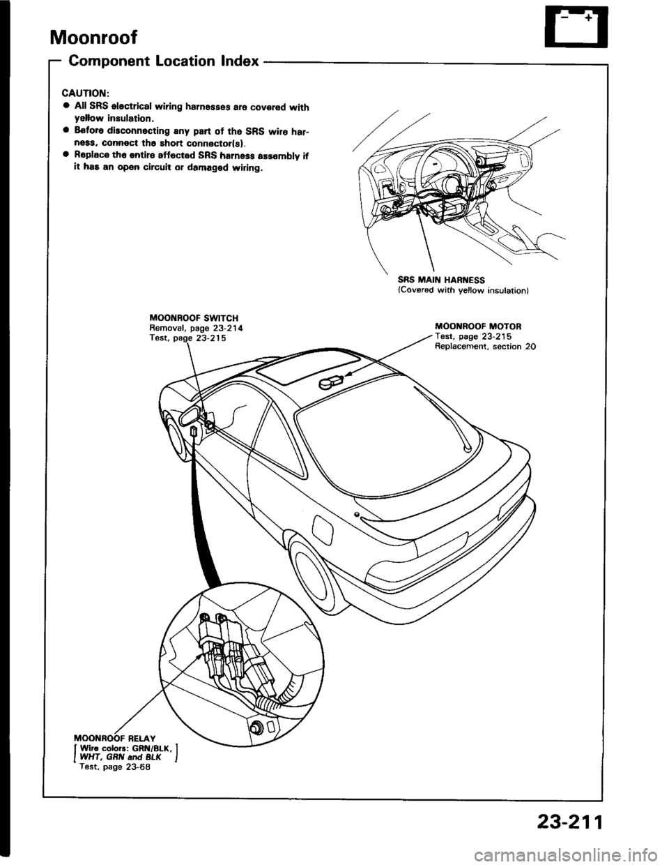
Gomponent Location lndex
a All SRS oloctrical wiring harnesses aro covared withyellow insulation,
a Eoforo disconnocting any part of tho SRS wire har-neaa, connoct th6 shon connector(sl.a Roplace th6 entire 8ff6cted SRS harness assombly ifit has an open circuit or damaged widng.
MOO BOOF SWTTCHRemov8l, page 23-214Test, page 23-215
SRS MAIN HARI{ESS{Covered with yellow insulation)
MOO ROOF MOTORTest, pag€ 23-215Replacoment, section 20
23-211
Page 1321 of 1413
Switch Test
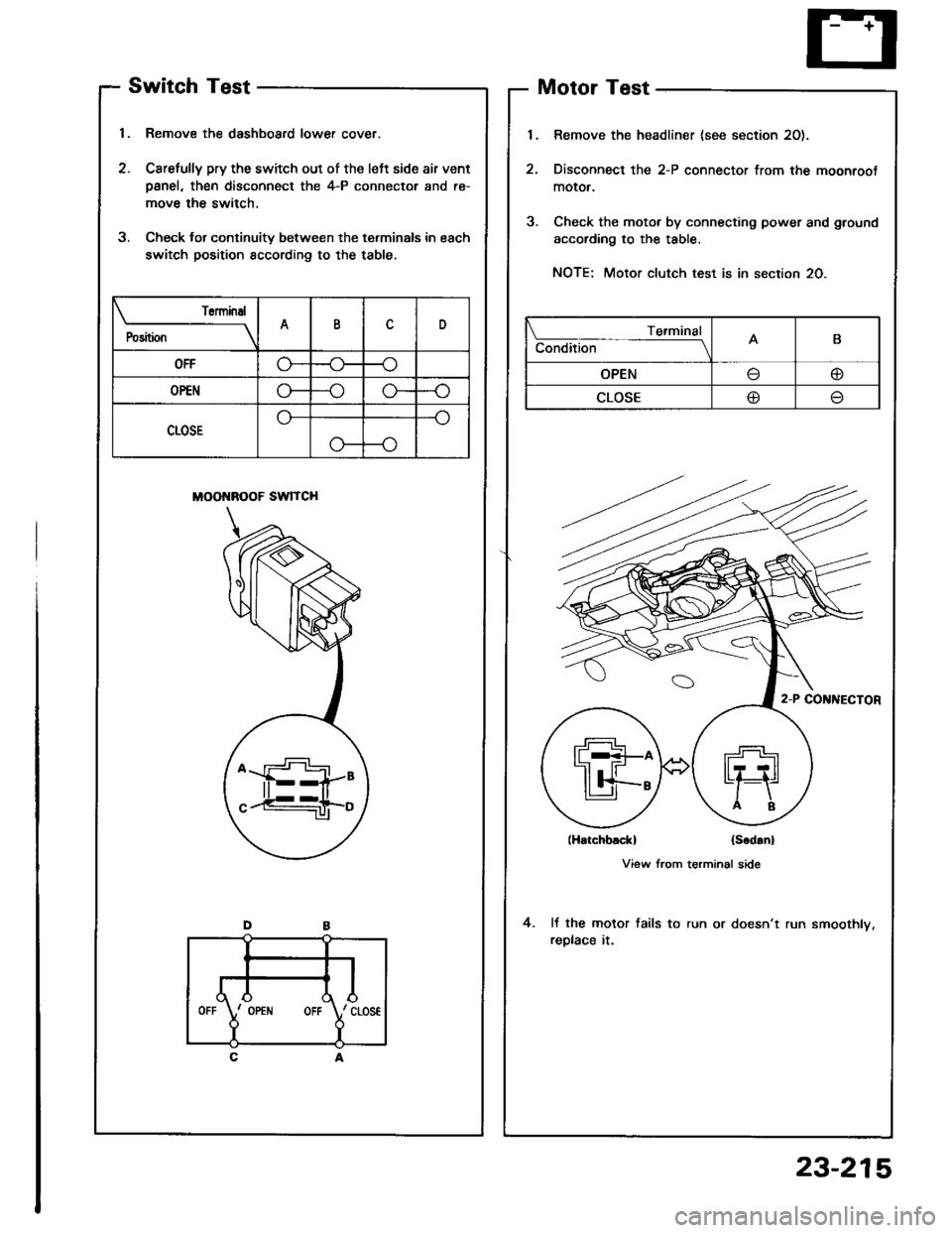
1, Remove the dashboard lower cover.
2. Carefully pry the switch out of the left side air vent
Danel, then disconnect the 4-P connector and re-
move the switch.
3. Check lor continuity between the terminals in each
switch position sccording to the table,
MOONROOF SWITCH
Motor Test
Remove the headliner (see section 20).
Disconnect the 2-P connector from the moonroot
moror.
Check the motor by connecting power and ground
according to the table.
NOTE: Motor clutch test is in section 20.
lHatchblckl (Scd!n)
View from terminal side
It the motor fails to run or doesn't run smoothly.
replace it.
4.
Torminal
P"ri i-
---__\AID
OFFG---o
OP€No---oG-
CLOSE
o---o
Te.minal
Condition -- ---------lAB
OPENo
CLOSE@
,l
rd\./ cLos€
Y
IOPEiIIOFF
23-215
Page 1324 of 1413
Power Mirrors
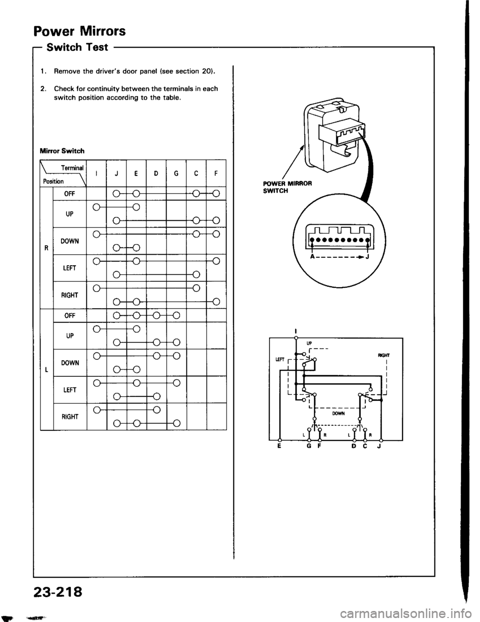
Switch Test
Remove the driver's door panel (see section 2O).
Check tor continuitv between the terminals in each
switch position according to the table.
Mirror Switch
rermrnal
Position \J
R
OFFG"
UP
-o
o--<>-
DOWN
-o
o--o
LEFTo-
-o
RIGHT
-o
o-
OFFo--o
UP
o--(J_
DOWN
-o
G--o
tEFT
-o
-o
RIGHTG-
P-o
23-214
aaaaaaaa
A-------+J
Page 1327 of 1413
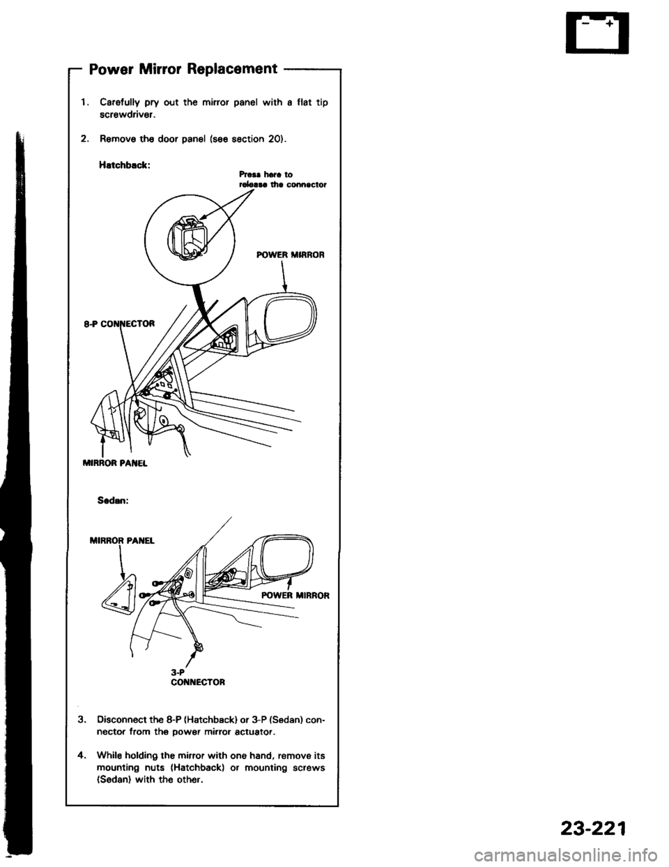
Power Mirror Replacement
2.
l.
t
Carefully pry out the miror panel with a llat tip
screwdriv€r.
Remove th€ door panel (see section 20).
HEtchblck:hca! hara torolalaa lha conn9clor
Disconnect the 8-P (Hatchb€ck) or 3-P (Sedan) con-
nector from thg oower mirror actuator.
While holding the mirror with one hand, remove its
mounting nuts (Hatchback) or mounting screws(Sedan) with the other.
4.
MIRROR PA]IEL
CO ECTOR
23-221
Page 1335 of 1413
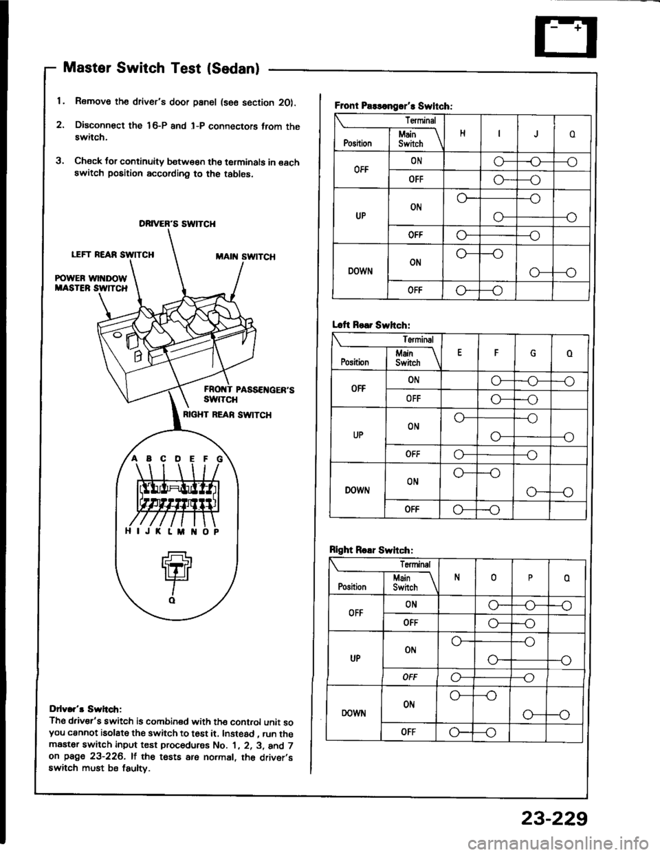
Master Switch Test (Sedan)
1. Remove the driver's door pan6l (sse section 2O).
2. Disconn€ct the 16-P and l-P connectors trom theswitch.
3. Check for continuity b€tw€€n tho terminals in eachswitch position according to the tables.
LEFT REARMAtit swtTcH
POWER wl DOWMASTEB SW]TCH
PASSEI{GER'SswtTcH
RIGHT REAN SW|TCH
Ddv.r't Swh.tr;
Th6 driv€r's switch is combined with the cont.ol unit soyou cannot isolate the switch to t6st it. Instead , run themaater switch input test procedurss No. 1 , 2. 3, and 7on page 23-226. lf the tests are normal, th6 driver,sswitch must be fsulty.
DRIVER'S SWTCH
ABCDE
Front Paslongrr't Swltch:
Terminal
HoI Main \Position I Swirch \
OFFONo-r)--o
OFFG----o
UPON
--o
O-
OFFo---o
DOWNON
o---o
OFFo--_o
Lcft Rear Swhch:
Terminal
EFoj Main IPosition I Switch \
OFFONo-o--o
OFFo---o
UPONo---o
--oo-
ut'fo---o
DOWNONo---o
G---o
OFF-o
Rlght Roar Swhch:
Teminal
N0oI Main If
Position I Switch \
OFFONG_o--o
OFFo---o
UPot'lo---o
--o
OFFo----o
DOWNONo---o
o--o
OFFG---o
23-229
Page 1336 of 1413
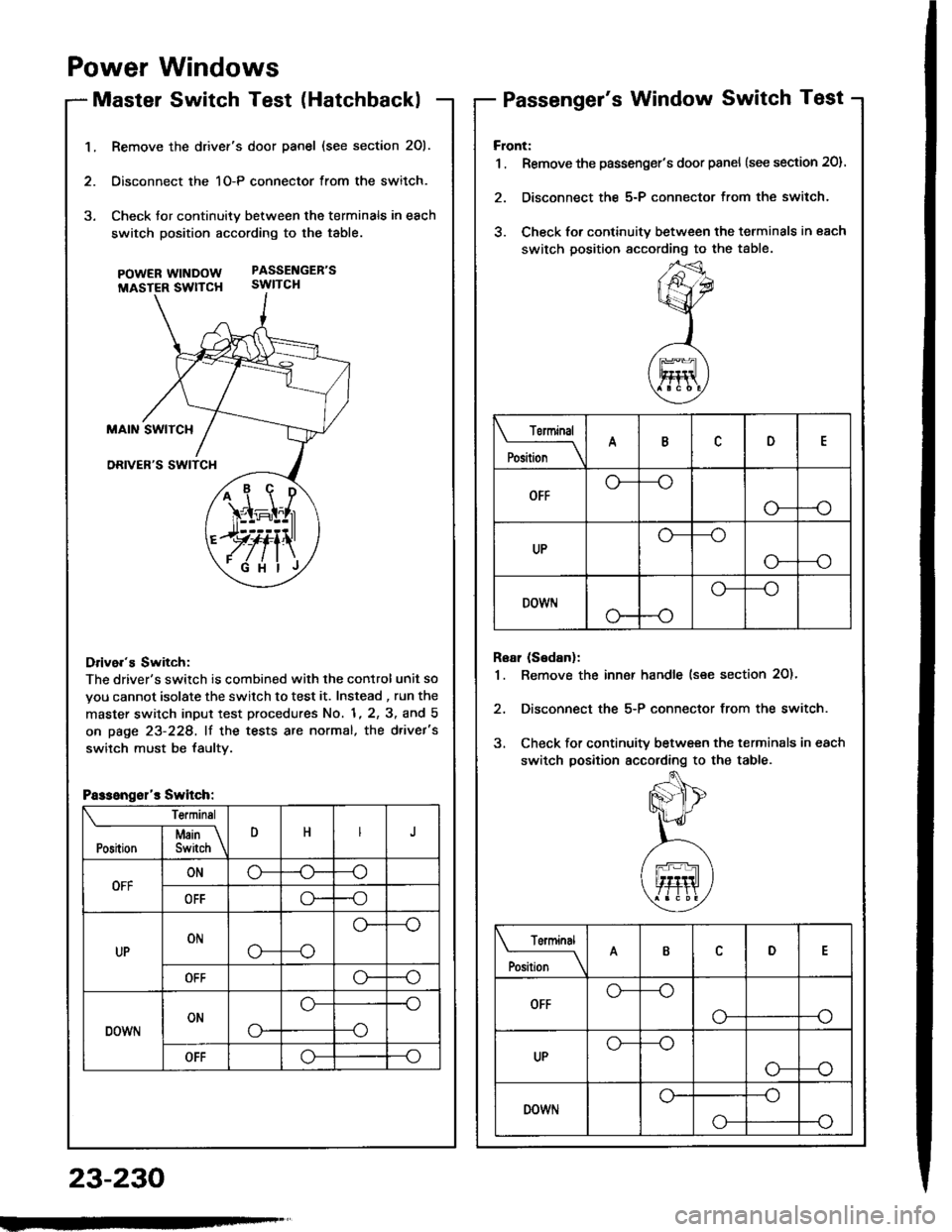
1.Remove the drivef's door panel (see section 201.
Oisconnect the 1O-P connector from the switch.
Check tor continuity between the terminals in each
switch position according to the table.
pOWERWTNDOW PASSENGEB'S
MASTER SWTTCH SWITCH
Drive.'s Switch:
The driver's switch is combined with the control unit so
you cannot isolate the switch to test it. Instead , run the
master switch input test procedures No. 1, 2, 3, and 5
on page 23-228, lf the tests are normal, the d.ivet's
switch must be faultv.
i1\i
\4r-I^l,r
)rvti\
.Fi'ilj
Passengsl'r Switch:
Te.minsl
DHJI Msin \Position I Switch \
OFFONo-(J--o
OFFo--o
UPONo---o
o--
OFFo--o
DOWNONo-
o--o
--o
OFFo--o
Power Windows
Master Switch Test (HatchbacklPassenger's Window Switch Test
23-230
Front:
1 . Remove the passenger's door panel {see section 20).
2. Disconnect the 5-P connector from the switch.
3. Check for continuity between the terminals in each
switch position sccording to the table.
Rear (Sedanl:
1. Remove the inn€r handle (see section 2O)'
2, Disconnect the 5-P connector from the switch.
3. Check for continuity between the terminals in each
switch position according to the table.
Torminal
il;_\
ARD
OFFo-
--o
UPo---o
G_--o
DOWr.lo---o
Terminal
;;__\ID
OFFG_--o
o---o
UPG_--o
o---o
DOWNo---o
o-
Page 1337 of 1413
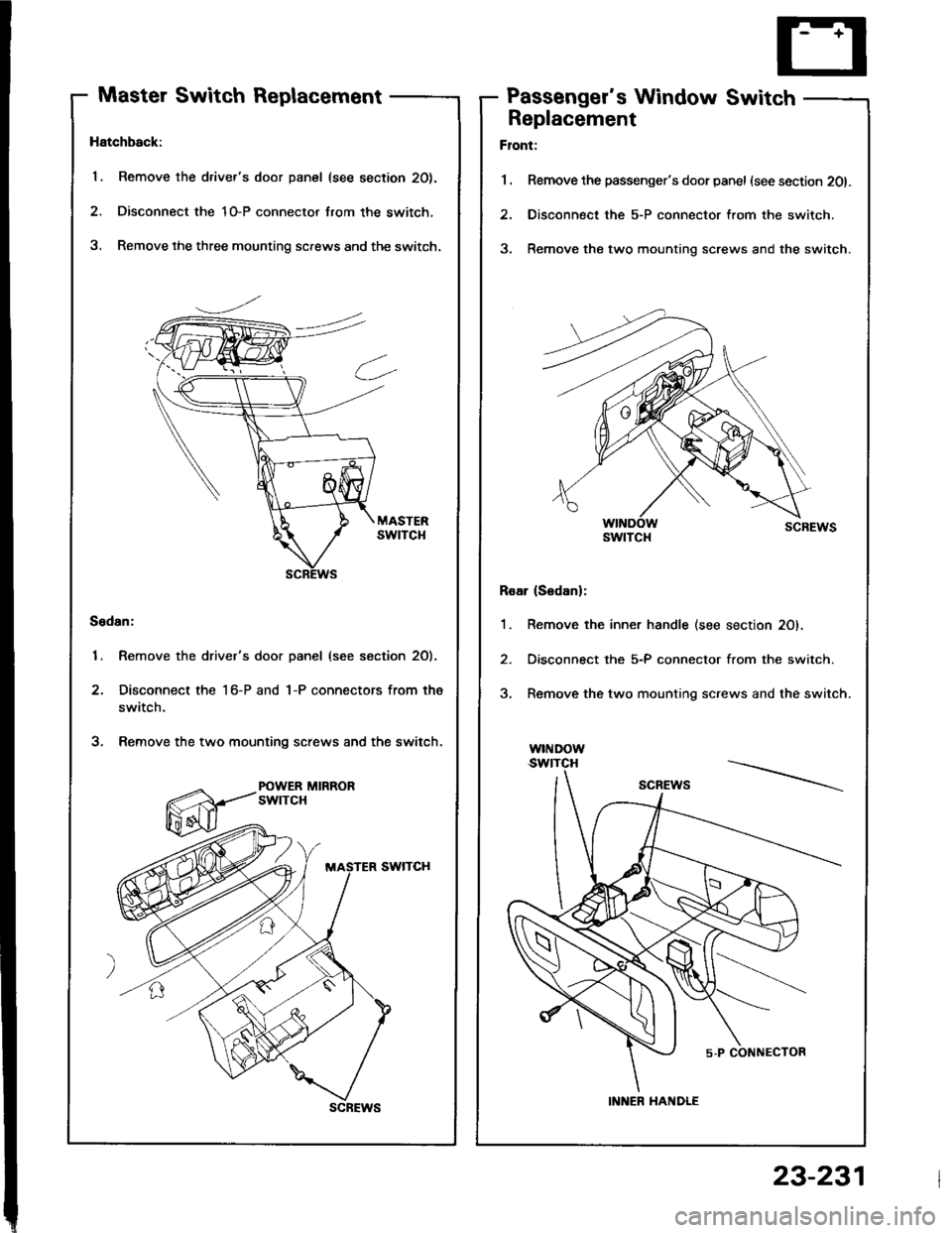
Master Switch ReplacementPassenger's Window Switch
Hatchback:
1. Remove the driver's door panel (see section 20).
2. Disconnect the 1O-P connector lrom the switch,
3, Remove the three mounting screws and the switch.
Sedan:
1. Remove the driver's door panel (see section 2O).
2. Disconnect the 1 6-P and 1-P connectors from the
switch.
3. Remove the two mounting screws and the switch.
POWER MIRRORswtTcH
scREws
Replacement
Flont:
1 . Remove the passenger's door panel (see section 201.
2. Disconnect the 5-P connector from the switch.
3. Remove the two mounting screws and the switch.
Roar (S6danl:
1. Remove the inner handle (see section 20).
2. Disconnect the 5-P connector from the switch.
3. Remove the two mounting screws and the switch.
w|I{Dow.swtTcH
swtTcl{
INNER HANDLE
23-231
Page 1338 of 1413
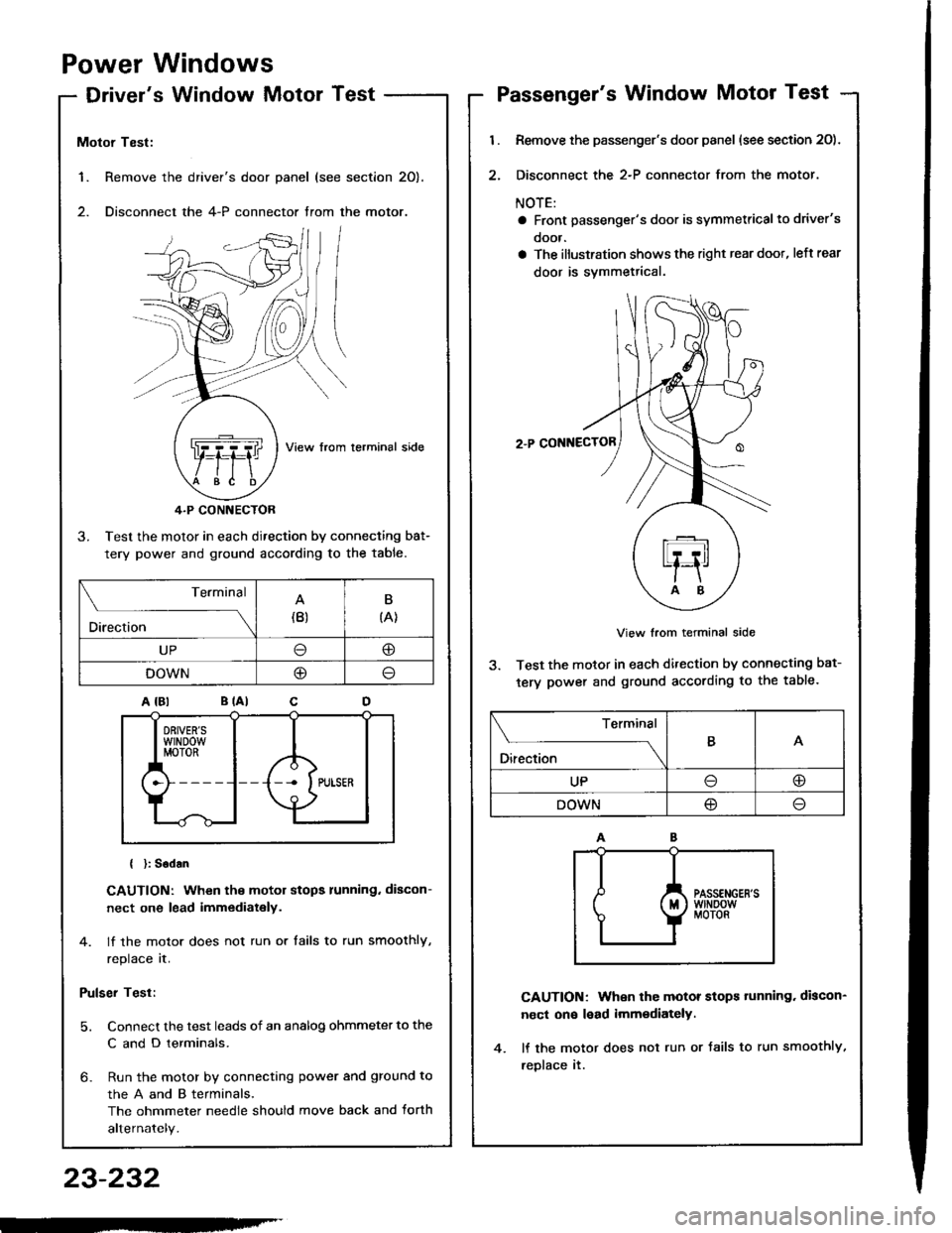
Power Windows
Driver's Window MotorTest
1. Remove the
2. Disconnect
Motor Test:
View from lerminal side
4.P CONNECTOR
3. Test the motor in each direction by connecting bat-
tery power and ground according to the table.
{ }: Sodan
CAUTION: When the motor stops running. discon-
nect one lead immediately.
4. lf the motor does not run or tails to run smoothly,
replace it.
Pulser Test:
5. Connect the test leads of an analog ohmmeter to the
C and D terminals.
6- Run the motor by connecting power and ground to
theAandBterminals,
The ohmmeter needle should move back and torth
alternately.
driver's door panel (see section 20).
the 4-P connector trom the motor.
. ,-,.f,/l l/
NZJI I
..Q]qql ,fiftl I
$e /tE \
Terminal
Direction(B)B
{A}
UP@
DOWNO
Passenger's Window Motor Test
l.
2.
Remove the passenger's door panel (see section 20).
Disconnect the 2-P connector from the motor.
NOTE:
a Front passenger's door is symmetricalto driver's
ooor.
a The illustration shows the right rear doot, left rear
door is svmmetrical.
2.P CONNECTOR
View from terminal side
3. Test the motor in each direction by connecting bat-
tery power and ground according to the table.
CAUTION: When the motor stops tunning. discon-
nect on€ lead imm€diately.
lf the motor does not run or Jails to run smoothly,
reDlace it.
Terminal
O*** \
BA
UPoo
DOWN@
23-232
-'