section 23 HONDA INTEGRA 1994 4.G Manual PDF
[x] Cancel search | Manufacturer: HONDA, Model Year: 1994, Model line: INTEGRA, Model: HONDA INTEGRA 1994 4.GPages: 1413, PDF Size: 37.94 MB
Page 619 of 1413
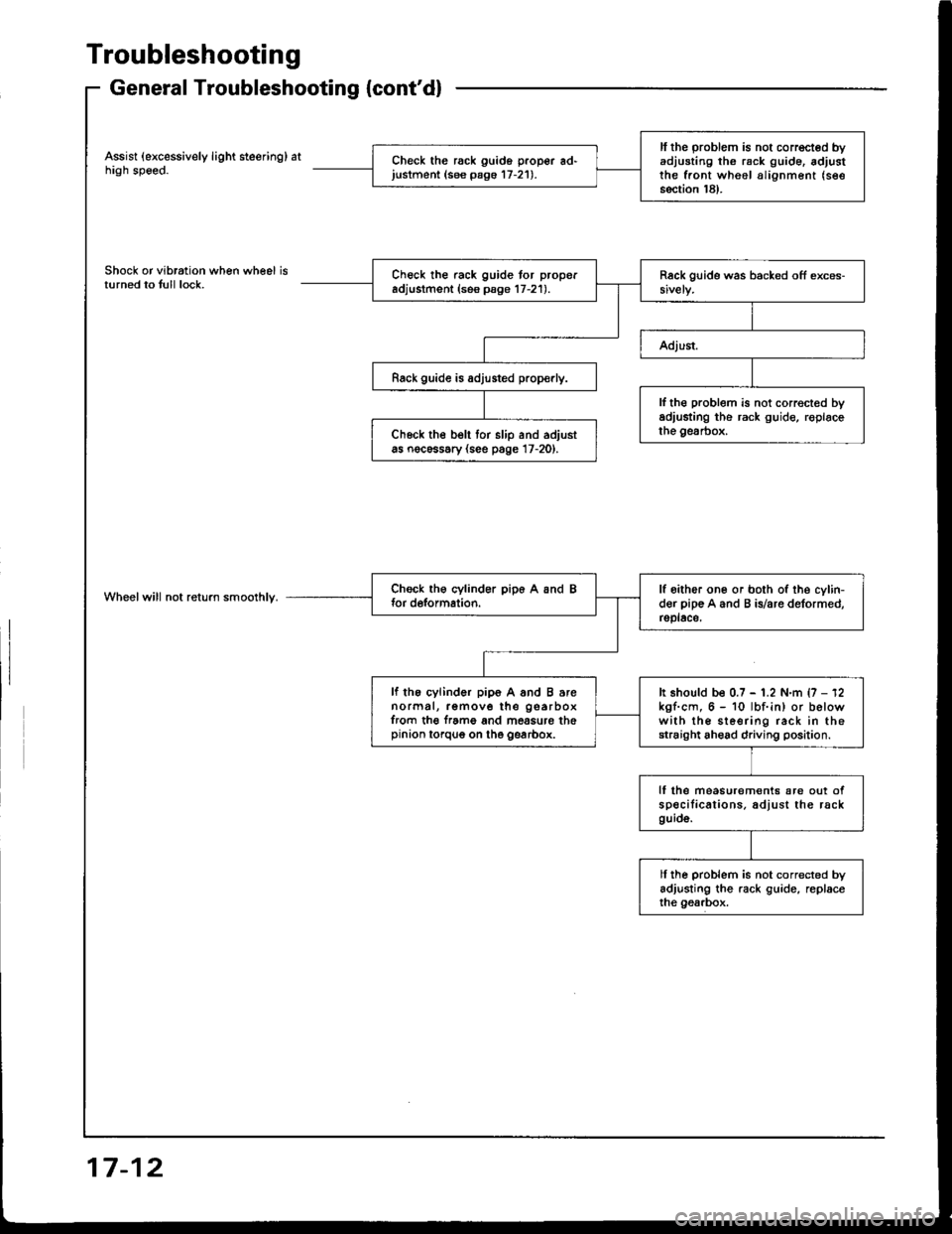
Troubleshooting
General Troubleshooting {cont'd}
Assist (excessively light steering) athigh speed.
Shock or vibration when wheel isturned to tull lock.
Wheelwill not return smoolhly.
ll the problem is not corrected byadjusting th6 rack g!ide. adjustthe front wheel alignment (see
section 18).
Check the rack guido proper ad'justment (see pago 17-21).
Check the rack guide tor properadjustment (ses psge 17-21).
Rack guide is adjusted prop€rly.
lf th€ problem is not correct€d byadiusting the rack guide, roplacethe gesrbox.Ch6ck the belt tor slip and adjustas nocessary (see page 17-20).
lf oither one or both of the cylin-der pip€ A and B is/are deformed,rsplace,
lf the cylinder pip6 A and B arenormal, remove the gearboxfrom th€ f.ame and mossure thepinion torqug on the gearbox.
It should be 0.7 - 1.2 N.m {7 - 12kgf.cm, 6 - 10 lbf.in) or belowwith the sleering rack in thestraight ahead driving position.
lf lhe measurem€nts are out ofspecilications. adjust the rackguid6.
ll ihe problem is not corrected byadjusting the rack guide, replaceihe gearbox.
17-12
Page 620 of 1413
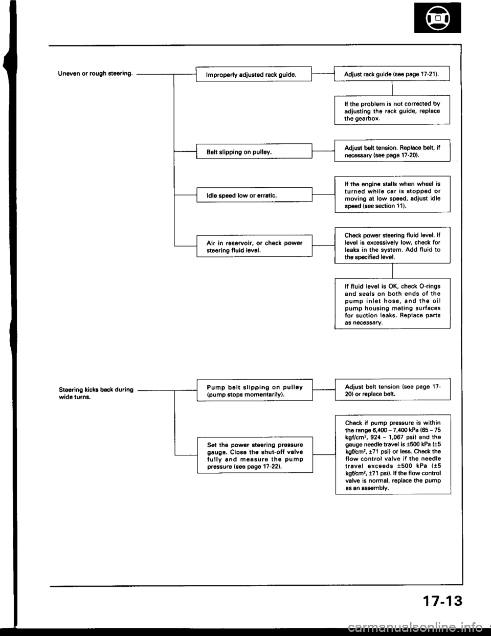
Unovon or rcugh 8te6ring.
3
Adjust rack guide (se€ poge 17-21).
ll the probl6m is not corrected bYadjusting lhe rack guide. replacothe gearbox.
Adiud bolt t€nsion. Roplace b€lt, ifn€c€ssary {s€e page 17-20).
lf the ongin€ stalls when wheel isturned whil€ car is stoDPed ormoving at low spoed, adjust idlesp€€d (soe section 1 1 ).
ldl6 soosd low or orrrtic.
Chock power sieering Iluid levol. Itlgv6l ie excessivoly low, ch€ck forleaks in the system. Add fluid totho spocifiod level.
Air in rssorvoir. or ch€ck pow6a
steoring fluid l6v6l.
lf fluid lev6l is OK, check o-ringsand seals on both €nds of ihopump inlet hose, and th€ oilpump housing mating surfacosfor suction leaks. Reolace oarts65 n€CeSSAry.
Adjust belt tonsion (see page 17-m) or r€Dlaco beh.Pump b6lt slipping on pull6y(pump stops momontarily).
Check if pump prossure is withinthe ranoe 6.400 - 7,100 kPa (65 - 75kgr/cm,, 924 - 1,067 psil and th6gsuge needls travol is 1500 kPa {15kgflctn2, t71 p6i) or less. Check theflow control valve if the needletr.vel €xcoods 1500 kPa {15kg?cm,, i71 psi). lf rhe flow controlvalvo is normal, replace th€ pump
as an assomblv.
Sel the power itooring p.oasuregaug6. Cl066 th€ shut-off v6lv6fully and m€a5uro tho pumppr6ssur6 (6s€ pagg 17-221,
7-1
Page 632 of 1413
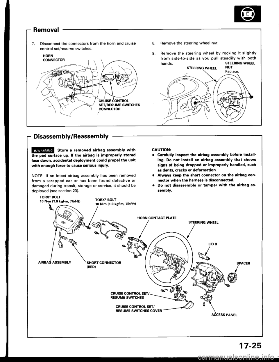
Removal
Disconnect the connectors trom the horn and cruise
control sevresume switches.
HORN
Disassembly/Reassembly
8.Remove the steering wheel nut.
Remove the steering wheel by rocking it slightly
from side-to-side as you puil steadily with both
hands.STEERING WHEEL
STEERING WHEELNUTReplace.
@ store a removed airbag assembly with
the pad 3urfacs up. lf the airbag is improperly stored
face down, accid€ntal daployment could prop€l tho unit
with enough forca to cause serious iniury.
NOTE: lf an intact airbag assembly has been removed
from a scragoed car or has been found defective or
damaged during transit. storage or service, it should be
deployed (see section 23).
TORX6 BOLT
CAUTION:
C8r€{ully inspoct ihe sirbag assombly betors install.
ing. Do not install an airbag ass6mbly that 5how3
signs ol boing dtopped or improperly handled, such
as dents, crack3 or deformation.
Always k€gp tho short connector on the aitbag con-
nector when ths harnegg i9 disconnected.
Do not disassemble or tamper with the airbag as-
sombly.
STEERING WHEEL
10 N.m {1.0 kgf m, Tlbt.ttl
t
TORX6 BOLT10 N.m {1.0 kgf.m, 7lbf.ft)
LID
\s
SPACER
/
@
CRUISE CONTROL SET/NESUME SWITCHES
CRUISE CONTROL SET/RESUME SWITCHES COVER
HORN CONTACT PI-ATE
17-25
Page 652 of 1413
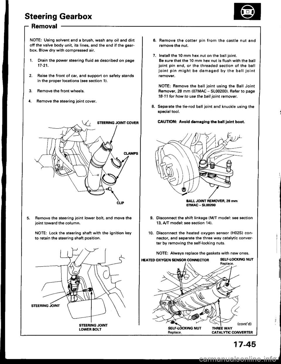
Steering Gearbox
Removal
NOTE: Using solvent and a brush, wash any oil and dirt
off the valve body unit, its lines, and the end if the gear-
box. Blow dry with compressed air.
1. Drain the power steering fluid as described on page
17 -21.
2. Rsise the front of car, and support on safety stands
in the propsr locations (see section 1).
3. Remove the front wheels.
il. Removs the st€ering joint cove.,
SIEERING JOIi{T COVEB
Remove the steering joint lower bolt, and move thejoint toward the column.
NOTE: Lock the steering shaft with the ignition key
to retain the steering shaft position.
Remove the cotter pin trom the castle nut and
removo the nut.
Installthe 10 mm hex nut on the balljoint.
Be sure that ths 10 mm hex nut is flush with the ball
ioint pin end, or the threaded section of the ball
ioint pin might be damaged by the ball iointremover.
NOTE: Remove the ball joint using the Ball Joint
Remover, 28 mm {07MAC - 5100200}. Refer to page
l8-11 fot how to use the ball joint rcmover,
Separat€ the tie-rod ball joint and knuckle using the
soscialtool.
CAUTION: Avold d.maging th. blllloint boot.
BALL JOlt{T REMOVER. 28 mm07MAC - SLqt2|X)
Disconnect the shift linkage {MfI model: see section
13, A/[ model see section 14).
Disconnect the heated oxygen sensor (H02S) con-
ngctor, and separate the three way catalytic conver-
ter by removing the s€lf-locking nuts.
NOTE: Always replace the gaskets with new ones.
OXycEt{S€NSOnOONNECTOR SELF.LOCKINGNUT
{cont'd)IHREE WAYCA?ALYTIC CONVERTEN
8.
10.
HEATED
Replacs.
17-45
Page 668 of 1413
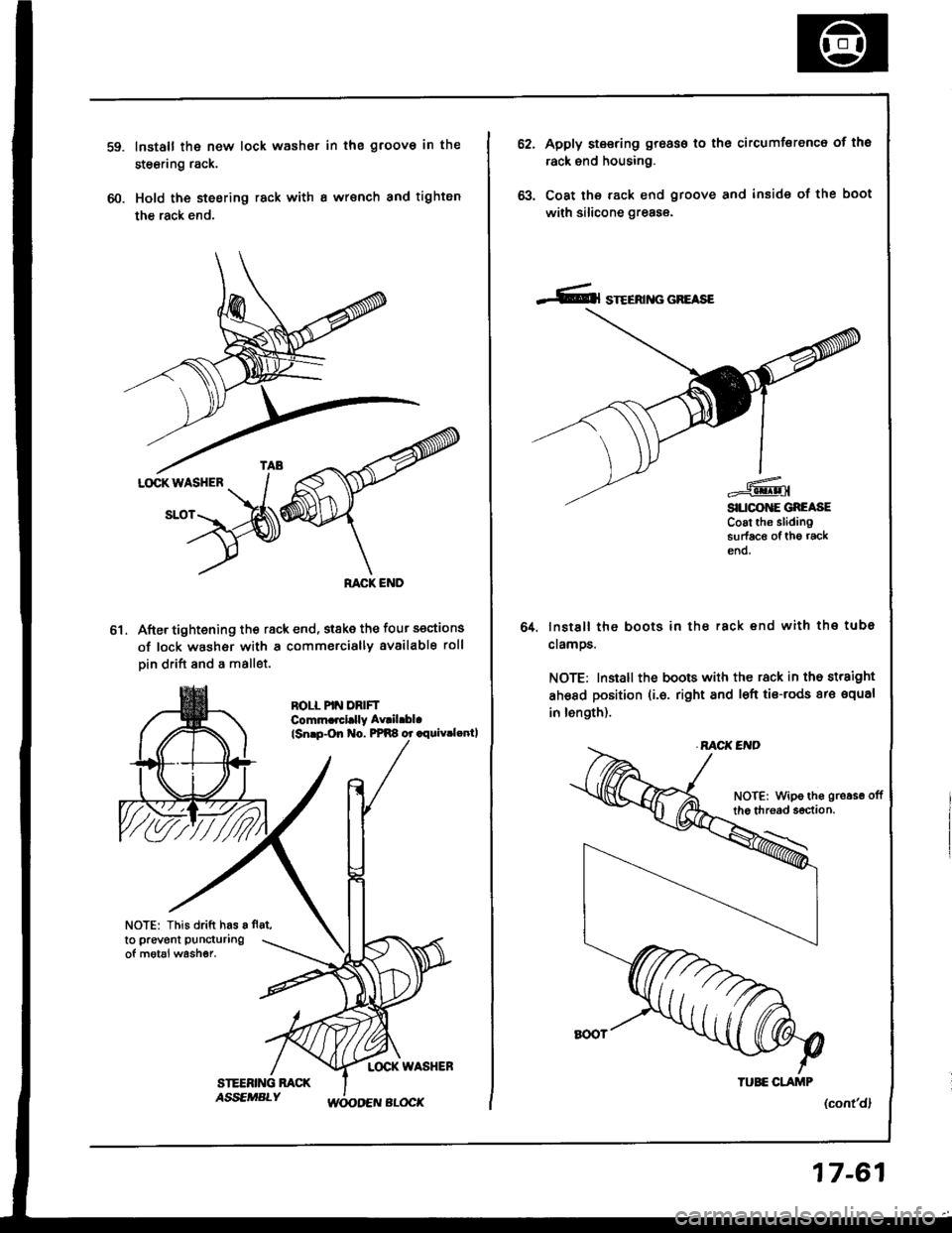
60.
Install the new lock washor in the groov€ in the
steering rack.
Hold the steering rack with I wrsnch and tighten
the rack end.
After tightening th€ rack end, stske the four sections
of lock washer with a commercially available roll
Din drift and a mallet.
ROLL PIN DRIFTComm.rcl.lly Av|il.bl.
lsnrp-On No. PPR8 or .rquiv.lenll
NOTE: This drift has a fl8t,
to prevent puncturing
of motal washer.
ol
62.Apply steering groass to the circumferenc6 of tho
rack end housing.
Coat the rack end groove and inside of the boot
with silicone greas€.
lnstsll the boots in ths rack end with the tube
clamos.
NOTE: Install the boots with the rack in the straight
ahsad position (i.6. right and l€ft tis-rods ar€ squal
in length).
(cont'dl
64.
NOTE: Wipe ths gro.se offthe thread s€ction.
TUEE CLAJTIP
17-61
Page 671 of 1413
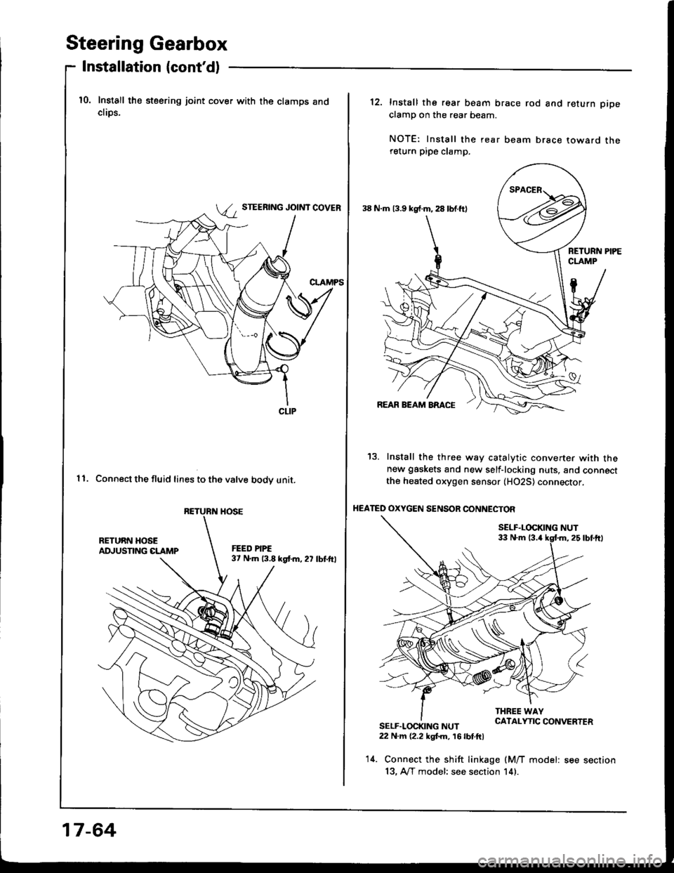
Steering Gearbox
Installation (cont'd)
10. Install the steering joint cover with the clamps andcliDs.
STEERING JOINT COVER
11. Connect the fluid lines to the valve bodv unit.
CLIP
RETURN HOSE
17-64
38 N.m 13.9 kg{.m, 28 lbf.ft)
12. Install the rear beam brace rod and return pipe
clamp on the rear beam.
NOTE: Install the rear beam brace toward thereturn pipe clamp.
13. Install the three way catalytic converter with thenew gaskets and new self-locking nuts, and connectthe heated oxygen sensor (H02S) connector,
HEATED OXYGEN SENSOR CONNECTOF
SELF.LOCKING NUT33 N.m 13.4
SELF.LOCKING NUT22 N.m (2.2 kgt m, 16 lbt.ftl
14. Connect the shift linkage (M/T model: see section
13, A/T model: see section 14).
Page 672 of 1413
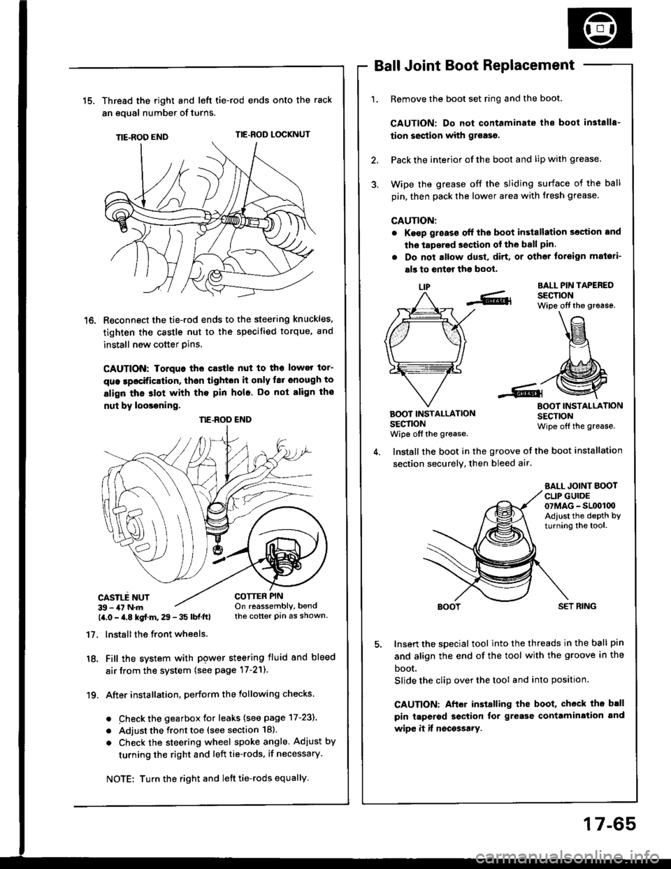
15.Thread the right and lefi tie-rod ends onto the rack
an eoual number of turns.
TIE-ROO ENDTIE.ROD LOCKNUT
R€connect the tie-rod ends to the steering knuckles,
tighten the castle nut to the specified torque, and
install new cotter pins.
CAUTION: Iorquo tho castle nut to tho lower tor-
que lpocification, thsn tighton it only far cnough to
align thc slot with tho pin hole. Do not align tho
nut by loosoning.
CASILE NUT39 - 47 N.m14.0 - a.8 kgf.m. 29 - 35 lbf ftl
17. lnstallthe front wheels.
18. Fill the system with pgwer steering fluid and bleed
air from the system (see page 17-21).
19. After installation. perform the following checks.
. Check the gearbox Jor leaks (see page 17-231
. Adjust the front toe (see section 18).
o Check the steering wheel spoke angle. Adjust by
turning the right and left tie-rods, if necessary.
Ball Joint Boot Replacement
Remove the boot set ring and the boot.
CAUTION: Do not contaminate ihe boot in3talls-
tion section with gr€aso.
Pack the interior of the boot and lip with grease.
Wipe the grease off the sliding surface of the ball
pin, then pack the lower area with fresh grease.
CAUTION:
. Ke€p g;eass off the boot in3tallation section and
tho laperad section of the ball pin.
. Do not altow dust, di.t, or other toreign mat6ti-
als to enter tho boot,
LIPBALL PIN TAPEREDSECTIONWipe off the grease.
BOOT INSTALLATIONSECTIONwiDe off the grease.
BOOT INSTALLATIONSECTIONWipe off the grease.
COTTER PINOn reassembly, bendthe cotter pin as shown.
Install the boot in the groove ot the boot installation
section securely, then bleed air.
SALL JOINT BOOTCLIP GUIDE07MAG - SL(x)l00Adiust the depth byturning the tool.
SET RING
Insert the special tool into the threads in the ball pin
and align the end of the tool with the groove in the
boot.
Slide the clip over the tool and into position
CAUTION: After installing the boot, check th. b.ll
pin taperod section tor grease contamiration and
wipe it if nocossary.
NE.ROD END
Turn the right and left tie-rods equally.
17-65
Page 924 of 1413
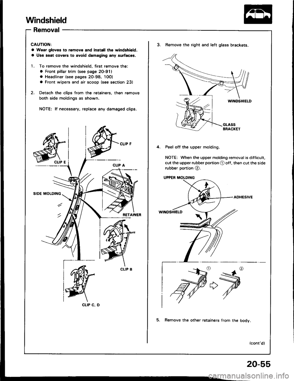
Windshield
Removal
CAUTION:
a Woar glovos to l€mov€ and install the windshiold,
a Us€ saat covers to avoid damaging any surfaces.
1. To remove the windshield, first remove the:
a Front pillar trim (see page 20-911
. Headliner (see pages 20-98. 1OO)
a Front wipers and air scoop (see section 23)
2. Detach the clips trom the retainers, then remove
both side moldings as shown.
NOTE: lf necessary, replace any dsmaged clips.
CLIP C, D
3. Remove the right and left glass brackels.
4. Peel oft the upper molding.
NOTE: When the upper molding removal is ditticult,
cut the upper rubber portion O off, then cut the side
rubber portion @.
UPPER MOLDII{G
ADHESIVE
WINDSHIELD
f--
5. Remove the other retainers trom the bodv.
lcont'd)
>
20-55
Page 930 of 1413
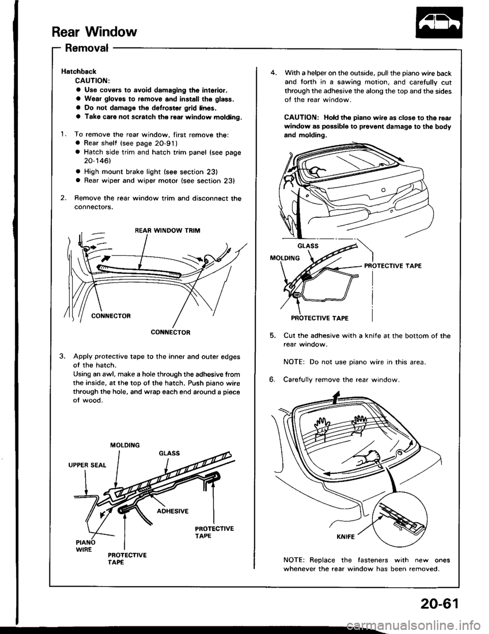
Rear Window
Removal
Hatchback
CAUTION;
a Use covsrs to avoid damaging tho interior.
a Wear gloves to romove and install the glass.
a Do not damags the defroster grid linss.
a Tako care not scratch th€ raar window molding,
1. To remove the rear window. first remove the:a Rear shelt (see page 20-91)
a Hatch side trim and hatch trim panel (see page
20-146)
. High mount brake light (see section 23)a Rear wiper and wiper motor (see section 231
2. Remove the rear window trim and disconnect the
connectors.
3. Apply protective tape to the inner and outer edges
of the hatch.
Using an awl. make a hole th.ough the adhesive trom
the inside. at the top ot the hatch. Push piano wire
through the hole, and wrap each end a.ound a piece
of wood.
CONNECTOR
MOLOING
4.With a helper on the outside, pullthe piano wire back
and forth in a sawing motion, and carefully cut
through the adhesive the along the top and the sides
oJ the rear window.
CAUTION: Hold ths piano wire as clos€ to the roat
window as possible to prevont damage to the body
and molding.
PROTECTIVE TAPE
Cut the adhesive with a knife at the bottom of the
aear window.
NOTE: Do not use piano wire in this area.
6. Carefully remove the rear window.
NOTE: Replace the fasteners with new ones
whenever the rear window has been removed.
PROTECTIVE TAPE
20-61
Page 964 of 1413
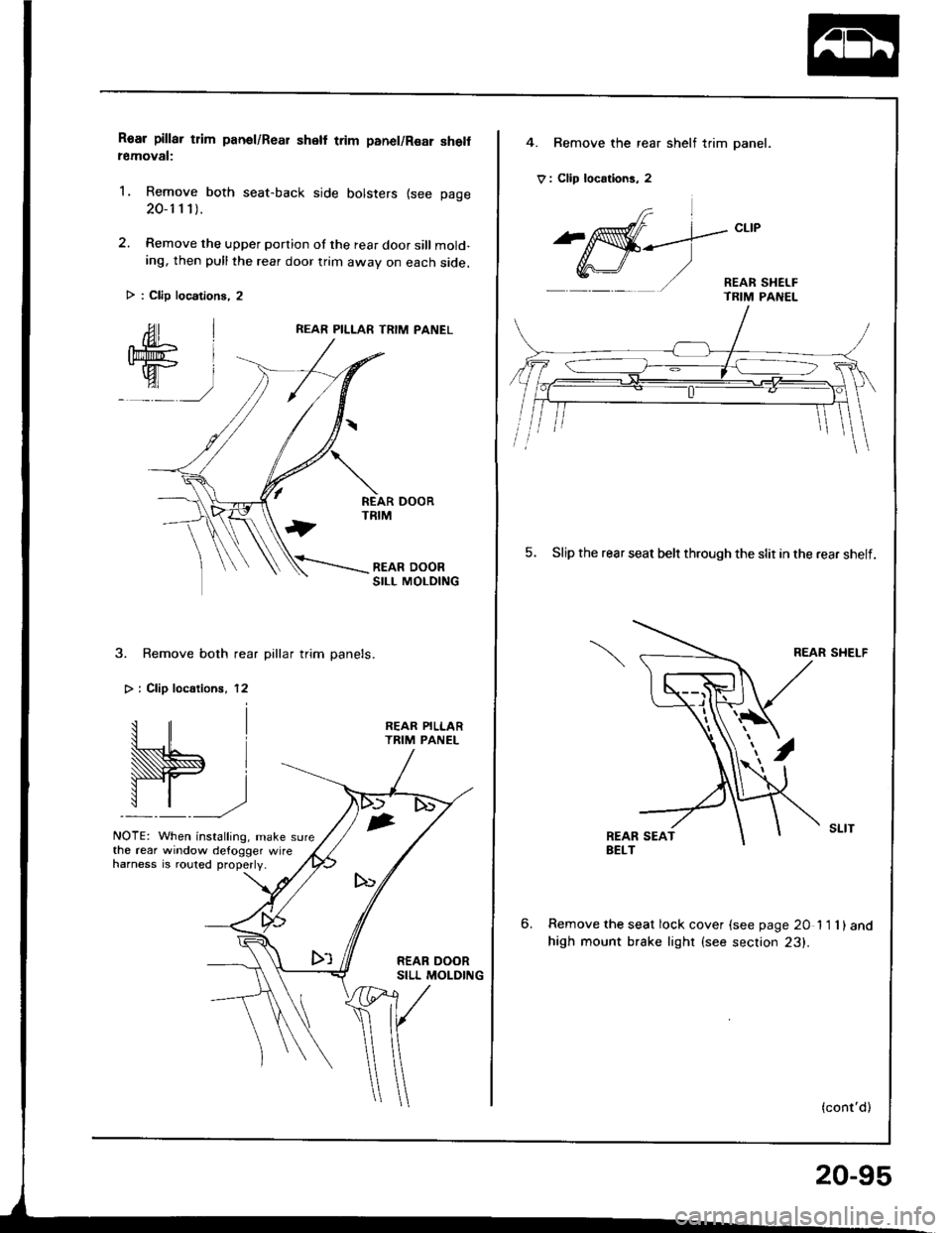
Roar pillar tlim panel/Rear shell trim panel/Rsar she removal:
1. Remove both seat-back side bolsters {see page
20-1 1 1).
2. Remove the upper portion of the rear door sill mold-ing, then pull the rear door trim awav on each side.
REAR PILLAR TRIM PANEL
3. Remove both rear pillar trim panels.
> i Clip localionr, 12
W.,
NOTE: When installing, make sure
REAR PILLARTRIM PANEL
the rear window defogger wireharness is .outed properly.
> : Clip locations, 2
4. Bemove the rear shelf trim panel.
V : Clip locrtions, 2
frl
^affi-_--.]-"t't
Y,r\-J/ '/ - REAR sHEr-F- TRIM PANEL
5. Slip the rear seat belr through the slit in the rear shelf.
REAR SHELF
6.Remove the seat lock cover {see page 20 11 1)and
high mount brake lighr (see section 23).
(cont'd)
20-95