HONDA INTEGRA 1994 4.G Workshop Manual
Manufacturer: HONDA, Model Year: 1994, Model line: INTEGRA, Model: HONDA INTEGRA 1994 4.GPages: 1413, PDF Size: 37.94 MB
Page 141 of 1413
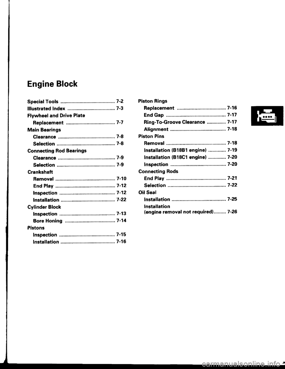
Engine Block
Speciaf Tools .............7'2
lllustrated Index ................................... 7-3
Flywheel and Drive Plate
Repfacement .........7-7
Main Bearings
Clearance ,.............. 7-8
Selection ................ 7-8
Connecting Rod Bearings
Clearance ............... 7-9
Selection ................ 7-9
Crankshaft
Removal .................7-10
End Play .................7-12
lnspection ........,,,.,,7-12
fnstallation .............7'22
Cylinder Block
Inspeetion ..............7-13
Bore Honing .....,.,,.7'14
Pistons
Inspaction ..............7-15
Installation .............7-16
Piston Rings
Replacement .........7-16
End Gap .................7-17
Ring-To-Groove C|earance,,,,.,,,...... 7 -17
Alignment ..............7-18
Piston Pins
Removal ........,........7-18
Installation (818B1 engine) ............. 7-19
fnstaffation (818C1 enginel ............. 7-20
fnspection ..............7-2O
Connecting Rods
End Play .................7-21
Sefeetion ..........,,,,,,7-22
Oil Seal
fnstaffation .............7-25
Installation
(engine removal not requiredl.. .......7-26
Page 142 of 1413
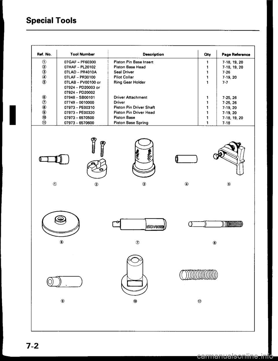
Special Tools
I
Raf. No. I Tool NumbcrDcacriptionOty I Pago Rotcrenc.
o
@
@
@
o
@
o
@
o
@
o
07GAF - PF60300
07HAF - P120102
OTLAD _ PR4O1OA
07LAF - PR30100
07LAB - PV00100 or
07924 - PD20003 or
01924 - PD20002
07948 - S800101
07749 - 0010000
07973 - PE00310
07973 - PE00320
07973 - 5570500
07973 - 6570600
Piston Pin Ease lnsert
Piston Base Head
Seal Oriver
Pilot Collar
Ring Gear Holder
Driver Attachment
Driver
Piston Pin Driver Shaft
Piston Pin Driver Head
Piston Base
Piston Base Spring
1
I
1'I
1
1
1
1
1
1
1
7-14,19,20
1-18, 19,20
7-19,20
7-1
7 -25, 26
7-19,20
1-19.20
1-18, 19, 20
1-18
Eg
o@,a\
o@
@@
0
7-2
Page 143 of 1413
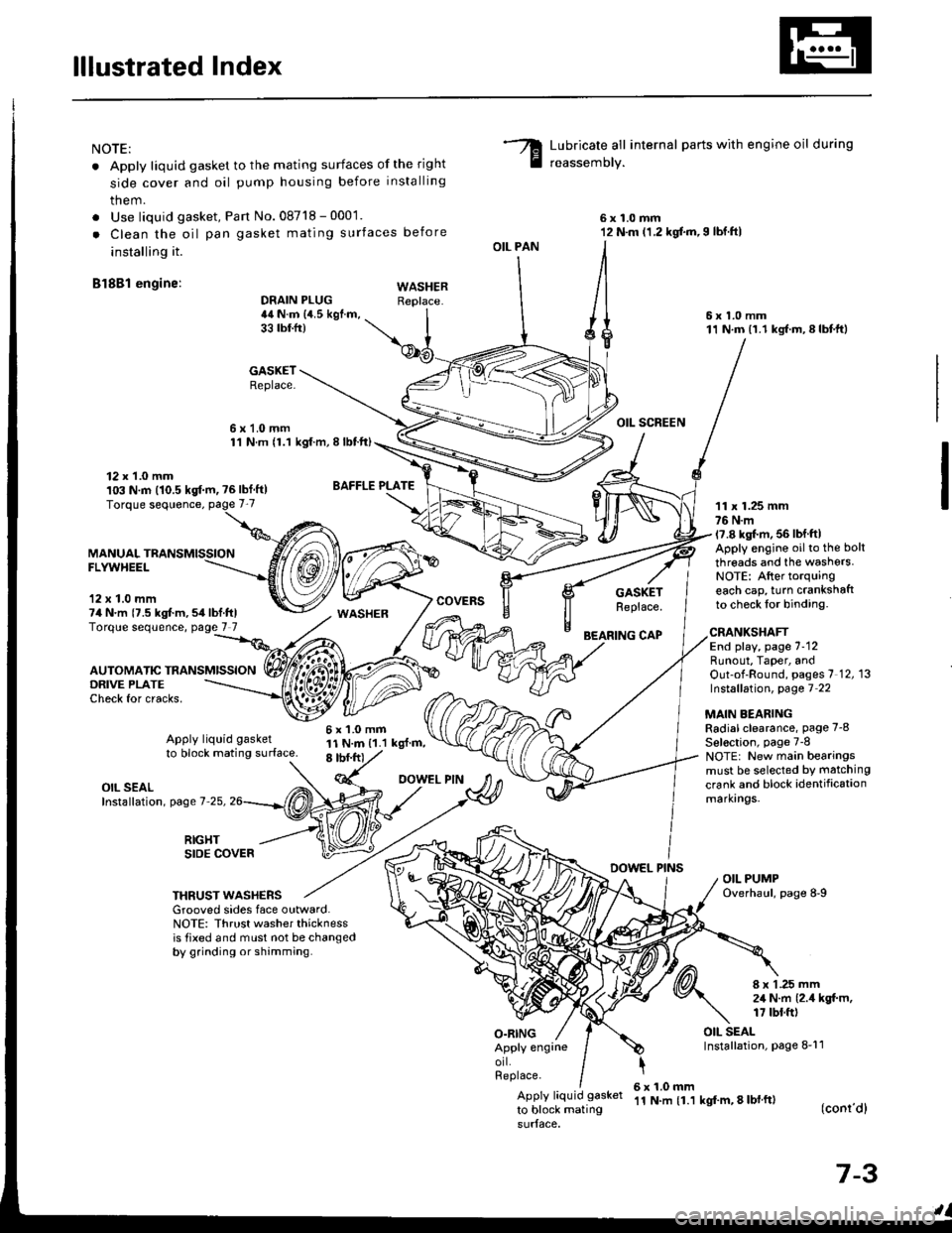
lllustrated Index
NOTE:
. Apply liquid gasket to the mating surfaces of the right
side cover and oil pump housing before installing
them.
. Use liquid gasket, Pan No.08718 - 0001.
. Clean the oil pan gasket mating surfaces before
installing it.
Bl8Bl engine: wAsHEF
Lubricate all internal parts with engine oil during
reassemory.
6x1.0mm12 N.m (1.2 kgf.m,I lbf.ftl
6x1.0mm11 N.m (1.1 kgf.m,8lbtft)
OIL SCREEN
11 x 1.25 mm76 N.m17.8 kgl.m, 56 lbf ftlApply engine oilto the bolt
threads and the washers.NOTE: After torquingeach cap, turn crankshaftto check lor binding.
DRAIN PLUG44 N.m {4.5 kgf.m,33 tbtfr)
GASKETReplace.
6x1.0mm1'l N.m {1.1 kgt.m, I lbtft)
OIL PAN
O.RING
GASKETReplace.
BEARING CAP
12 x 1.0 mm103 N.m (10.5 kgf.m, ?6lbf ft)
MANUALFLYWHEEL
'12 x 1.0 mm74 N.m {7.5 kgt m,54lbf.ftlTorque sequence, page 7 7
DRIVE PLATECheck for cracks,
AUTOMATIC TRANSMISSION
WASHER
6x1.0mm11 N.m {1.1 kgl.m,8 tbf.frt
CRANKSHAFTEnd play, page 7-12Runout, Taper, andOut-of-Round, pages 7 12, 13Instsllation, page 7 22
MAIN BEARINGRadial clearance, page 7-8
Sel€ction, page 7-8NOTE: New main bearingsmust be selected by matching
crank and block identificationmarkrngs.
Apply liquid gasket
to block mating surface.
OIL SEALInstallation, page 7-25,
RIGHTSIDE COVERDOWEL PINSOIL PUMPOverhaul, page 8-9THRUST WASHERSGrooved sides face outward.NOTE: Thrust washer thicknessis tixed and must not be changedby grinding or shamming.
8 x 1 .25 mm2,1 N.m {2.4 kgt m,17 tbt.ft)
OIL SEALInstallation, page 8-11Apply engrneorl.Replace.
Apply liquid gasket
to block mating
6x1.0mm'11 N.m {1.1 kgf'm, 8 lbl ft)(conr'dl
7-3
Page 144 of 1413
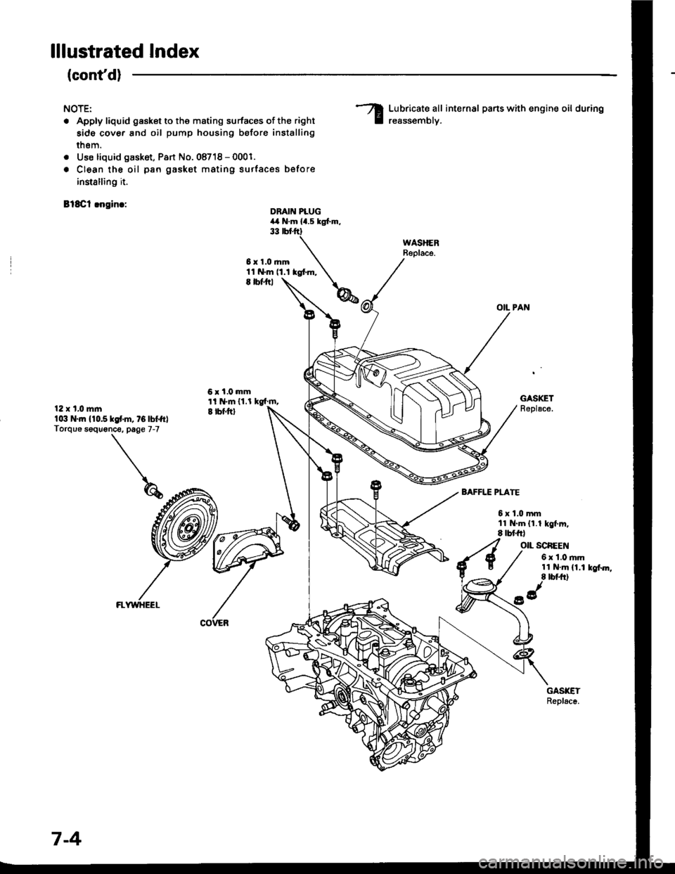
lllustrated Index
(cont'd)
NOTE:
. Apply liquid gasket to the mating surfaces of the right
side cover and oil pump housing before installing
thsm.
. Use liquid gask6t, Part No. 08718 - 0001.
. Clean the oil pan gasket mating surtac€s before
innalling it.
Bl8Cl !ngin.:
Lubricate all internal parts with engine oil during
reassemblv.
OIL PAN
DBAIN PLUG4,a N.m la.s tgl.m.33 rbr.ftt
6x1.0mm11 N.m (1.1 kgt m,E |bfitl
6x1.0mmti l*m 11.l kgf m,I tbf.ftl
GASKETReplace.12 x t.0 mlnlo:t N.|n 110.510f'm, tG lbffrlTorque soquonce. page 7-7
BAFFLE PLATE
6xl.0mmll N.m (1.1 kgt m.8 tbt frl
O|L SCAEEN
6 x 1.0 rim11 N.m (1.1 kgf.m,8 tbt ft)
FLWYHEEL
7-4
Page 145 of 1413
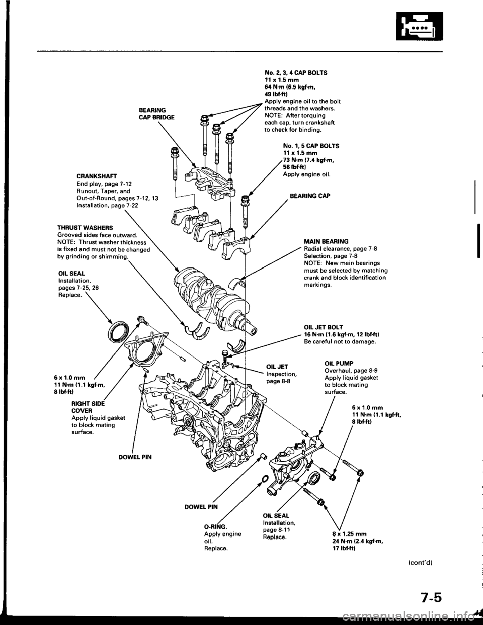
BEARINGCAP BRIDGE
No. a 3, /a CAP BOLTSll x 1.5 mm64 N.m {6.5 kgt m,49 tbf.ftlApply engine oilto tho boltthreads and the washers.NOTE: Aftertorquingeach cap, turn crankshaftto check for binding.
No. 1,5 CAP BOI-TS11 x 1.5 mm73 N.m {7.4 kgf.m,56 tbt'ft|Apply engine oil.
BEARING CAP
CRANKSHAFTEnd play, page 7-12Runout, Taper, andOut-of-Round, pages 7'12. 13Installation, page 7-22
YHRUST WASHERSGrooved sides lace outward.NOTE: Thrust washer thicknessis fixed and must not be chano€d
MAIN BEARINGRadial clearance. page 7 8S6l€ction, page 7-8NOTE: New main bearingsmust be selected by matchingcrank and block identificationmarxrngs.
OIL JEI BOLY16 N.m 11.6 kg{'m, 12lbtftlBe caretul not to damage.
OIL PUMPOverhaul, page 8-9Apply liquid gasket
to block matingsurface.
OIL SEALInstallation,pages 7-25, 26
11 N.m 11.1 kgt m,8 lbf ftl
Replace.
6r1.0mm
OIL JETInspection,page 8-8
OIL SEALInstellelion,page 8-11Replace.
RIGHT SIDECOVERApply liquid gasketto block matingsurface.
6x1.0mm11 N.m {1.18 rbf.ftlkSf.ft,
DOWEL PIN
DOWEL PIN
O.RING.Apply engineorl.Replace.
8 x 1.25 mm24 N.m {2.4 kgt m,17 tbtft)
(cont'd)
7-5
Page 146 of 1413
lllustrated IndexF
(cont'd)
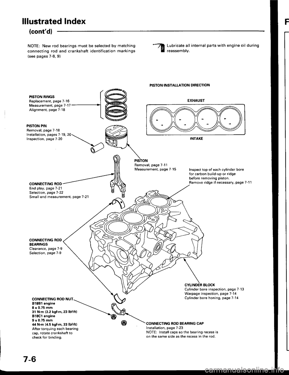
NOTE: New rod bearings must be selected by
connecting rod and crankshaft identification
(see pages 7-8,9)
matching
marKrngs
Lubricate all internal parts with engine oil during
reassemorv.
PISTON RINGSReplacement, page 7'16Measurement. page 7-17Alignment, page 7 18
PISTON PINRemoval, page 7-18lnstallation, pages 7 19, 20Inspection, page 7'20
PISTON INSTALLATION DIRECTION
EXHAUST
INTAKE
Removal, page 7'11Measurement, page 7 15Inspect top of each cylinder borefor carbon build-up or ridgobetore removing piston.Remove ridge it necessary, page 7'11CONNECTING ROOEnd play, page 7-21
CONNECTING RODEEARINGSClearance, page 7-9Selection, page 7-9
CONNECTING ROD NUT818B1 ongine8x 0.75 mm31 N.m {3.2 kgf.m,23 lbf ftl818C1 engine9 x 0.75 mma,a N.m (4.5 kgt m, 33 lbf.ft|After torquing each bearangcap, rotate crankshaft tocheck for binding.
r-(,
Selection, page 7-22Small end measurement. page 7-21
BLOCXCylinder bore inspection, page 7 13Warpage inspection, page 7'14Cylinder bore honing, page 7-14
CONNECTING ROD BEARING CAPInstallation, page 7'23NOTE: Install caps so the bearing recess ison the same side as the recess in the rod.
r@
-1@
Page 147 of 1413
Flywheel and Drive Plate
Replacement
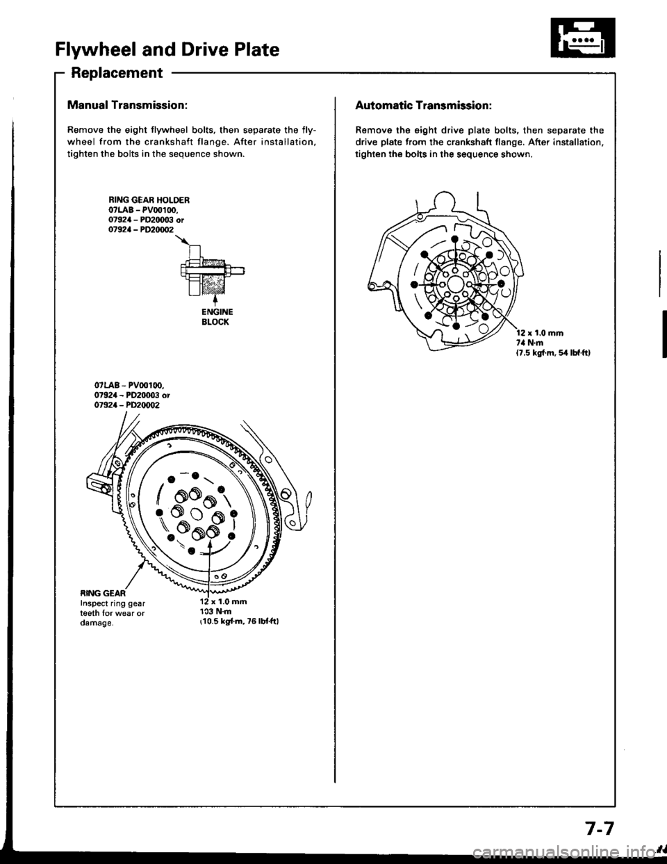
Manual Transmission:
Remove the eight flywheel bolts, then separate the lly-
wheel from the crankshaft flange. After installation,
tighten the bolts in the sequence shown.
r10.5 kgi.m,76lbt.ftl
RING GEAR HOLOERo?LAB - PV00100,07924 - PO2IX)03 or07924 - PD20/m�2
\
n.t=?4
fut!!-+-rt=tz-21I lvaz'Z-+
ENGINEBLOCK
o -o.r \
/ oo^t,
\..?bi
/ AK{:{AAo
rs#*ffi_9
Automatic Transmission:
Remove th€ eight drive plate bolts, then separate the
drive plate from the crankshaft flange, After installation,
tighten the bolts in the sequence shown.
r t.0 mmt,l N.m(7.5 kg{.m, 54 lbf.ft}
7-7
Page 148 of 1413
Main Bearings
Clearance
To check main bearing-to-journal oil clearance,
remove the main caps and bearing halves.
Clean each main journal and bearing half with a
clean shop towel.
Place one strip of plastigage across each main iour-
nal.
NOTE: lf the engine is still in the car when you bolt
the main caD down to check clearance, the weight
of the crankshaft and flywheel will flatten the plasti-
gage further than just the torque on the cap bolt,
and give you an incorrect reading. Fot an accurate
reading, support the crank with a iack under the
counterweights and check only one bearing at a
trme.
Reinstall the bearing caps and cap bridge (818C1
engine only) then torque the bolts.
81881 engine:77 N'm (7.8 kgf'm,56lbl'ft)
818C1 engine:
No. 1,5 cap bolts 73 N'm (7.'l kgt'm,56lbf'ftl
No. 2, 3, 4 cap bolts 6a N'm (6.5 kgf'm, 49 lbf'ftl
NOTE: Do not rotate the crankshaft during inspec-
tron,
Remove the cap bridge (818C1 engine only), caps
and bearings again, and measure the widest part oJ
the plastigage.
Main Bearing-to-Journal Oil Cl€arance:
Standard (Newl:
No. 1, 2, 4, 5: 0.024 - 0.042 mm
10.0009 - 0.0017 inl
Service Limit: 0.050 mm {0.0020 inl
No. 3:0.030 - 0.0,18 mm(0.0012 - 0.0019 inl
Ssrvice Limit: 0.060 mm {0.0024 inl
PLASTIGAGE STNIP
lf the plastigage measures too wide or too narrow,
(remove the engine if it's still in the car), remove the
crankshaft. and remove the upper half of the bear-
ing. Install a new. complete bearing with the same
color code (select the color as shown in the right
column), and recheck the clearance.
CAUTION: Do not file, shim, or scrapo ihe bo.rings
or the caps to adiust clearance.
lf the plastigage shows the clearance is still incor-
rect, try the next larger or smaller bearing (the color
listed above or below that one), and check again.
NOTE: lf the Droper clearance cannot be obtained
by using the appropriate larger or smaller bearings,
reolace the crankshaft and start over.
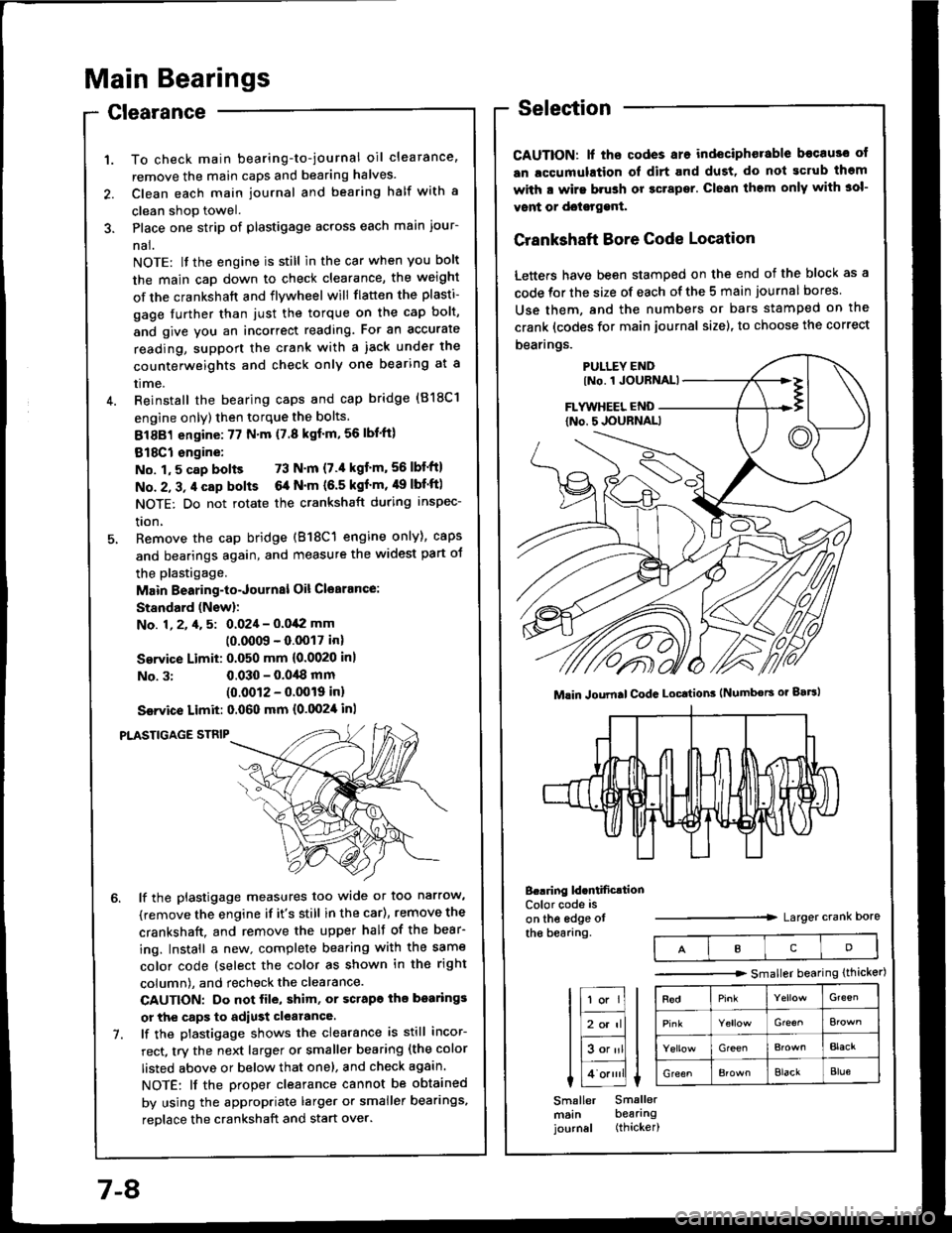
Selection
CAUTION: lf ths codes are indeciphorable becau3o ot
an lccumulation ol dirt and dust, do not gcrub thgm
with a wirs brush or gcrapsr. Clean them only with 3ol-
vont or doisrggnt.
Crankshaft Bore Code Location
Letters have been stamped on the end of the block as a
code for the size of each of the 5 main journal bores
Use them, and the numbers or bars stamped on the
crank (codes for main journal size), to choose the correct
bearings.
B..ring ld.ntificrtionColor code is
on the edge otthe bearang.Larger crank Dore
Mlin Joumal CodG Locttion3 (Numbors or gaBl
IcD
tr;;lIl
Itr-tl
lE;tl I tlHlt
I Lo.""li L
Smaller Smallermsin bearingjournal (thicker)
-------.r> smaller bearing (thicker)
G'een
Gre€^
GreenBlacr
GreenElackBlue
7-8
Page 149 of 1413
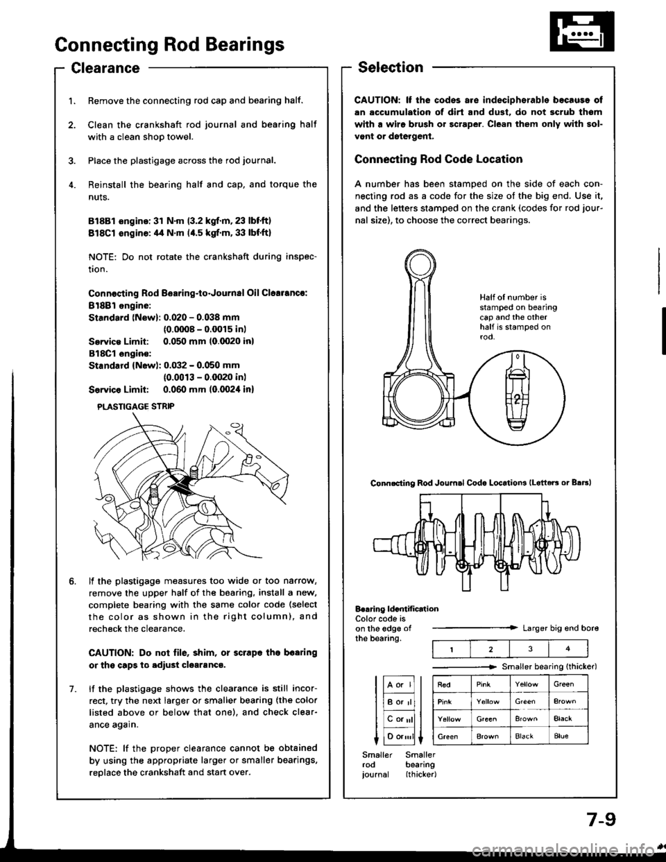
ConnectingRod Bearings
ClearanceSelection
CAUTION: lf the codss are indeciphsrable bocause of
an accumulation of dirt and dust. do not scrub tham
with a wiro brush or scraper. Clean them only with sol-
vont or dotetgenl.
Connecting Rod Code Location
A number has been stamped on the side of each con-
necting rod as a code for the size of the big end. Use it,
and the letters stamped on the crank (codes for rod jour-
nal size), to choose the correct bearings.
tF;l I tl-lf
liBor'rll I
lEalll t
I 1o.,,,'ll L
Smaller Smallerrod bearingjournal (thicker|
Half of number isstamped on bearingcap and the otherhalf is stamped onrod.
Conn.cting Rod Joumsl Codc LocatioN lLotteE or B.trl
Berring ldcntification
t23
Color code ison the edge ofthe bearing.Larger big end bore
Smaller bearing {thicker)
RedGr€€n
Elack
Bla€kBlue
1. Remove the connecting rod cap and bearing half.
2. Clean the crankshaft rod journal and bea.ing half
with a clean shoo towel.
3. Place the plastigage across the rod journal.
4. Reinstall the bearing half and cap, and torque the
nuts.
81881 sngino: 31 N'm 13.2 kgf.m,23 lbt'ft)
818C1 sngine: 4,1 N.m 14.5 kgf.m. 33 lbf'ft}
NOTE: Do not rotate the crankshaft during inspec-
tion.
Connecting Rod B€aring-to-Journal Oil Clcalancr:
8l88l ongine:
Standard (New): 0.020 - 0.038 mm
{0.0008 - 0.0015 in)
Servica Limit: 0.050 mm (0.0020 inl
818C1 engin€:
Standard (New): 0.032 - 0.050 mm
(0.0013 - 0.(XP0 inl
Service Limit: 0.060 mm (0.0024 in)
ll the plastigage measures too wide or too narrow,
remove the upper half of the bearing. install a new,
complete bearing with the same color code (select
the color as shown in the right column), and
recheck the clearance.
CAUTION: Do not file, shim, or scrape lhe bearing
or the capg tq adiust clgaranca.
lf the plastigage shows the clearance is still incor-
rect, try the next la.ger or smaller bearing {the color
listed above or below that one), and check clear-
ance again.
NOTE: lf the proper clearance cannot be obtained
by using the appropriate larger or smaller bearings,
reolace the crankshaft and stan over.
1.
PLASTIGAGE STRIP
Page 150 of 1413
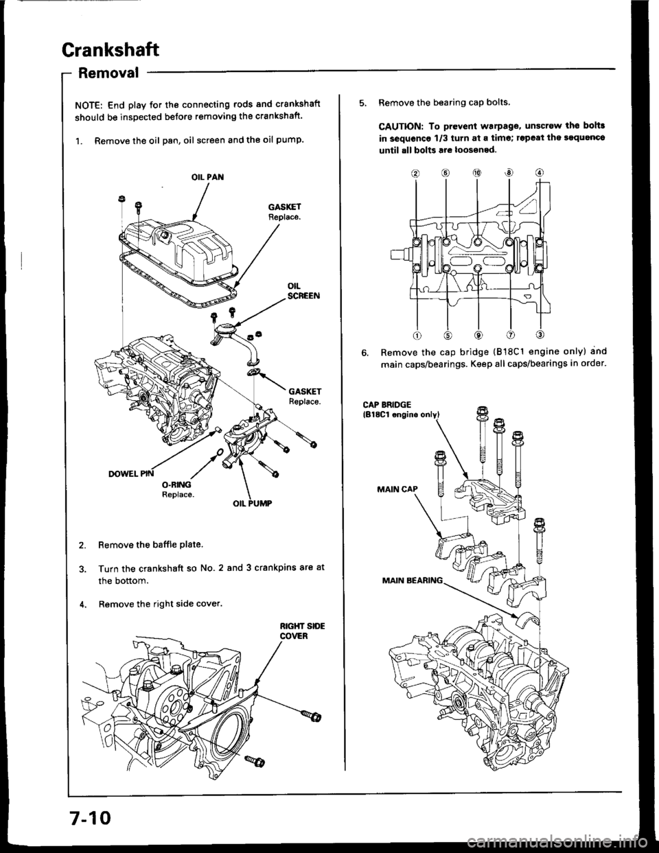
Crankshaft
Removal
NOTE: End play for th€ connecting rods and crankshaft
should be inspected betore removing the crankshaft.
1. Remove the oil Dan, oil screen and the oil pump.
Remove the baffle plate.
Turn the crankshaft so No.2 and 3 crankpins ar€ at
the bottom.
Remove the right side cover.
OIL PAN
7-10
o@@
5, Remove the bearing cap bolts,
CAUTION: To prevent warPag€, unscrew ths bohr
in 3equoncg 1/3 turn at a tim€; rspeat ihe sgquanco
until all bolts are loos€ned.
Remove the cap bridge {818C1 engine only} and
main caps/bearings. Keep all caps/bearings in order.