Dash HONDA INTEGRA 1994 4.G User Guide
[x] Cancel search | Manufacturer: HONDA, Model Year: 1994, Model line: INTEGRA, Model: HONDA INTEGRA 1994 4.GPages: 1413, PDF Size: 37.94 MB
Page 236 of 1413
(From page 1 1-43)
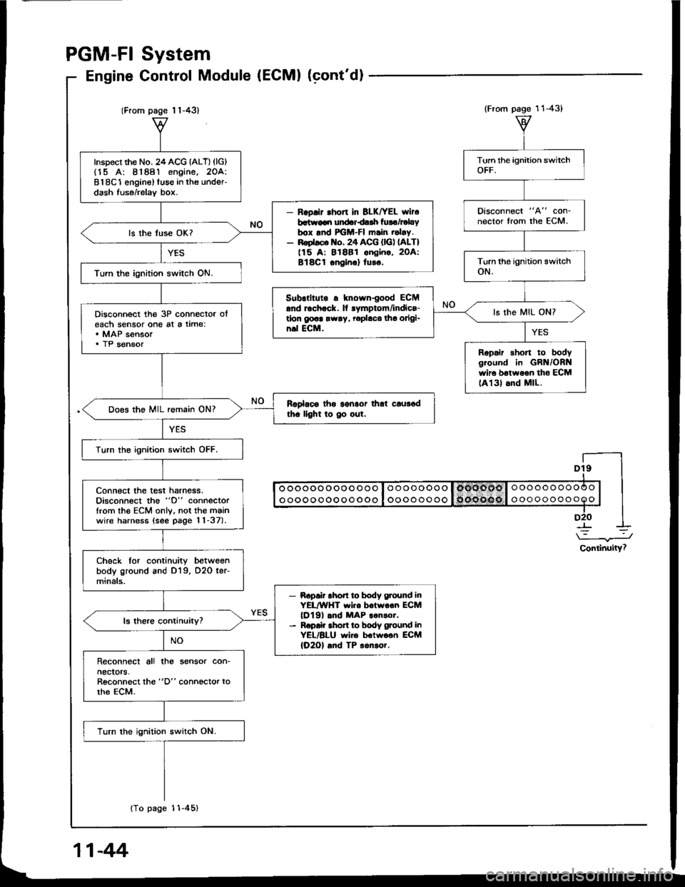
Inspect the No. 24ACG {ALT) (lG)(15 A: 81881 engine, 2OA:818C1 enginel fuse in the under-dash fuse/relav box.
- R.pllr .hon in BLK|rEL wlr6batr.v€qr undariair luro/Fbybox lnd FGM-FI m.in .obv.- noebco lto. 24 ACG {lG) nLT)(15 A: 81881 ongin., 2OA:Bl8Cl onein.l tu!6.
ls the fuse OK?
Turn the ignition switch ON.
Disconnect the 3P connector oteach sensor one al a time:. MAP sensor. TP sensor
Rcplaoo thg lgnlor that caur6dth. llght to Oo out.Does the MIL remain ON?
Turn the ignition switch OFF.
connect the test harness.Disconnect the "D" connectorfrom th€ ECM only, not the mainwire harness (see page 11-37).
Check tor continuity betweenbody ground and D19, O2O ter-minals,
- Bapai? rhod ro body g.ound inYEL/WHT wi.e boiwoon ECM(Dl9) .nd MAP ..n3or.- R.p!k shon to body ground inYEL/BLU wire b.lwo6n ECM(O2Ol .nd TP 3on!or.
Reconnect all tho sensor con-necrors,Reconnect the "D" connector torhe ECM.
Turn the ignition switch ON.
{To page 11-45}
System
Control Module (ECMI (cont'dl
PGM-FI
Engine
Dt9I
I oooooooooo ooo I oooooooo I omoool o oooooooooo | |I ooooooooooooo I oooooooo 1o('oe(lo I ooooooooooo | |-lD2O I
\-.J
Continuity?
(From page 11-43)
Disconnect "A" con-nector from the ECM.
Subrtltute r knowngood ECM.nd rochock. ll lymptom/indics-tlon g@a rw!y, rephco tho origi-n.l ECM.
ls the MIL ON?
Ropair short to bodygiound in GRN/ORNwir6 botwoon tho ECMlA131 6nd MlL.
11-44
Page 281 of 1413
ldle Gontrol System
Startel Switch Signal
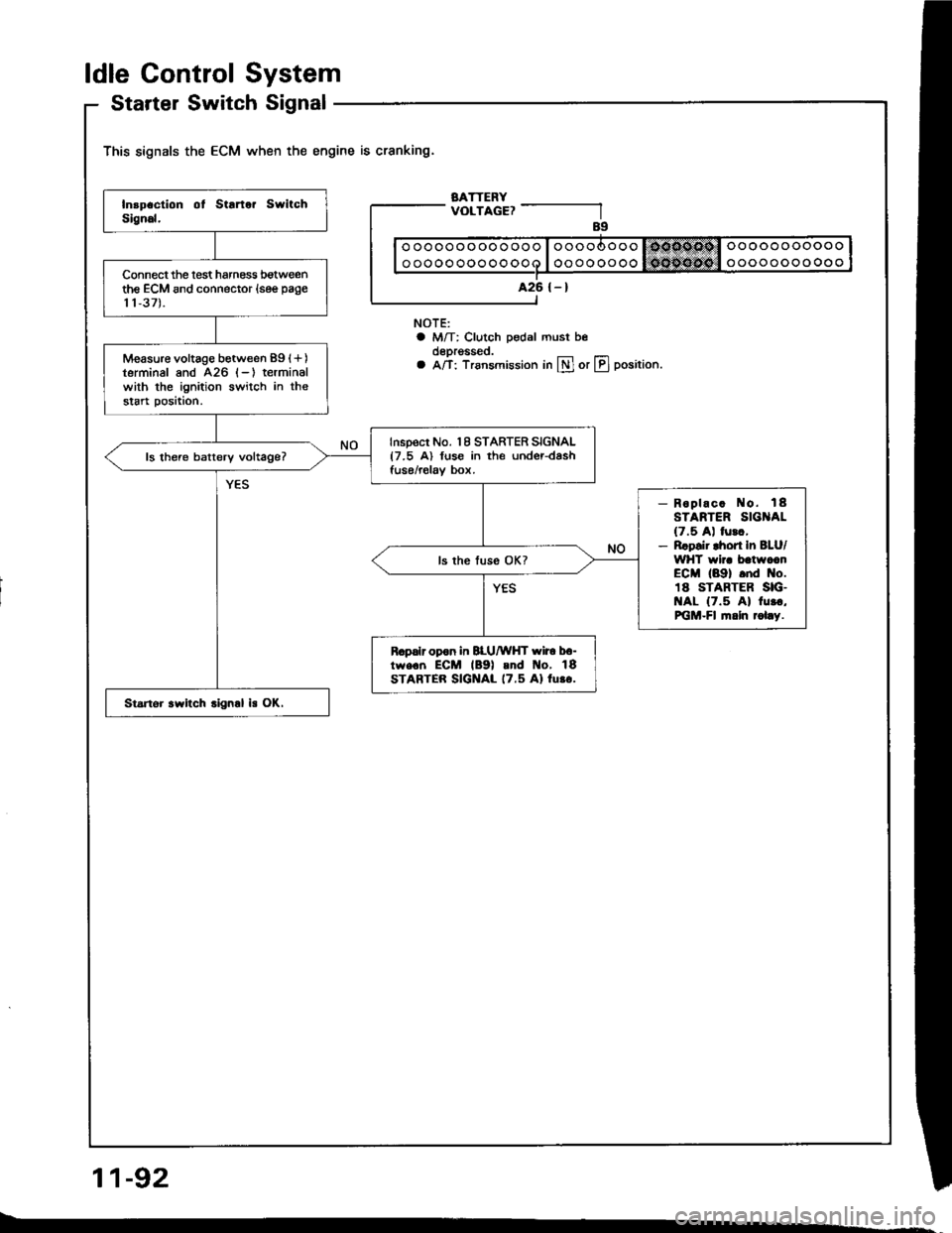
This signals the ECM when the engine is cranking.
BATTERYVOLTAGE?
NOTE:a M/T: Clutch pedal must beoeprgsseo.a A/T: Trsnsmission in lll or LIJ position.
11-92
ooooooooooooo
oooooooooooo
A26 {-}Connect the lest harness botweenthe ECM and connector (see page
11,37).
Measure voltage between 89 (+)
terminal and 426 (-) terminalwith the ignition switch in thestart position.
Inspect No. 18 STARTER SIGNAL{7.5 A) fuse in the under-dashfuse/relav box.ls there batterv voltage?
- Roplac. No. 18STARTER SIG AL(7.5 A) lurc,- Rrpsir lhort In BLU/WHT wir. batwccnECM (89) .nd No.18 STARTER SIG.t{AL {7.5 Al 1u..,PiGM-Fl fi.ln rol.y.
R.palr opon in BLU/WHT wir6 b6-tw€.n ECM lB9l and t{o, 18STARTER SIGNAL 17.5 Al lu.o.
Startor .witch .ign.l is OK.
Page 301 of 1413
![HONDA INTEGRA 1994 4.G User Guide Fuel Supply System
PGM-Fl Main Relay (contdl
BLU
BLU/wHt
Bt-xNOTE:. M/T: Clutch pedal mustbe depressed.. A/T: Transmission in
N or E] position.
BLK/ YEL/YEL BLK
Tloubloshooting
{To page 11 113}
- Eng HONDA INTEGRA 1994 4.G User Guide Fuel Supply System
PGM-Fl Main Relay (contdl
BLU
BLU/wHt
Bt-xNOTE:. M/T: Clutch pedal mustbe depressed.. A/T: Transmission in
N or E] position.
BLK/ YEL/YEL BLK
Tloubloshooting
{To page 11 113}
- Eng](/img/13/6067/w960_6067-300.png)
Fuel Supply System
PGM-Fl Main Relay (cont'dl
BLU
BLU/wHt
Bt-xNOTE:. M/T: Clutch pedal mustbe depressed.. A/T: Transmission in
N or E] position.
BLK/ YEL/YEL BLK
Tloubloshooting
{To page 11 113}
- Engino will not sran.- Inspection oI PGM-FI main re-lay and rolay ha.n6!a.
Check lor continuitv between BLKterminal @ and body ground.
Rapair open in BLK wire botwoonPGM-FI main.el6y and GIO'l llo-catod at thormostot housingl.
Measure the voltage betweenYELMHT terminal @ and bodyground.- Roplaco th. ECU IECMI(15 Allus6 in tho under-hood fu!o/r6-lay box.- Ropair opan or short in theYEL/WHT wil6 botwosn thePGM-FI main rolay and the ECU
{EcMl 115 A} luso.
ls there battery voltage?
Turn the ignition switch ON.
Measure the voltage betweenBLK/YEL terminal @ and bodyground.- Reolac. ths No. 24 ACG {ALT}{lcl {15 A:81881 6ngino, 20A: Bl8Cl engin6) tuse in thoundor-dash fuso/rolaY box.- Ropaii op6n or rhon in thoBLK/YEL wiro botwoen thoPGM-FI main ielay and th€ No.24 ACG {ALT) flG} {'�15 A:818Bi ongine, 20 A: 818Cionginol fuso.Turn the ignition switch to theSTART position.
Measure the voltage betweenBLUMHT terminsl @ and bodyground.
- Replaco the l\lo. 18 STARTERSIGNAL {7.5 A} fuso in thoundor-dash fuaa/rolay box.- R6pai. open or short in thoBLU/WHT wire botweon thsPGM-FI main relay and tho No.1A STARTER SIGNAL I7.5 AIluse.
11-112
Page 395 of 1413
The Automatic Transmission is a combination of a 3-e,ement torque convefter and triple-shaft electfonically controlled
automatic transmission which provides 4 speeds forward and 1 speed reverse. The entire unit is positioned in line with
the engine.
Torque Converter, Gears and Clutches
The torque converter consists of a pump, turbine and stator assembly in a single unit, The torque converter is connected
to the engine crankshaft so they turn together as a unit as the engine turns. Around the outside of the torque converter
is a ring gear which meshes with the starter pinion when the engine is being staned. The entire torque converter assem-
bly serves as a flywheel while transmitting power to the transmission mainshaft.
The transmission has three parallel shafts, the mainshaft. countershaft and sub-shaft. The mainshatt is in line with the
engine crankshaft.
The mainshaft includes the clutches for 1 st, and 2ndl4th, and gears for 3rd. 2nd, 4th, reverse and l st (3rd gear is in-
tegral with the mainshaft, while reverse gear is integral with the 4th gear).
The countershaft includes the 3rd clutch and gears Ior 3rd, 2nd,4th, reverse, lst and parking. Reverse and 4th gears
can be locked to the countershaft at its center, providing 4th gear or reverse, depending on which way the selector is moved.
The sub-shaft includes the lst-hold clutch and gears for 1st and 4th
The gears on the mainshait are in constant mesh with those on the countershaft and sub-shaft. When certain combina-
tions of gears in the transmission are engaged by the clutches, power is transmitted from the mainshaft to the counter-
shaft via the sub-shatt to provide @, E, tr. tr and @ position.
Electronic Control
The electronic control system consists of the Transmission Control Module {TCM), sensors, and 4 solenoid valves. Shift-
ing and lock-up are electronically controlled for comfortable driving under all conditions.
The TCM is located below the dashboard, behind the left side kick panel on the driver's side.
Hydraulic Control
The valve bodies include the main valve body, secondary valve body, regulator valve body. servo body, and lock-up valve
body throuqh the respective separator plates.
They are bolted on the torque converter housing.
The main valve body contains the manual valve, 1-2 shift valve, 2-3 shift valve, Clutch Pressure Cont.ol (CPC) valve,
4th exhaust valve, relief valve, and oil pump gears.
The secondary valve body contains the 4-3 kick-down valve,3-2 kick-down valve,2-3 orifice cont.ol valve, 3-4 shitt
valve, orifice control valve. modulator valve, and servo control valve
The regulator valve body contains the pressure regulator valve. lock-up control valve, torque converter check valve, and
cooler check valve.
The servo bodv contains the servo valve which is integrated with the reverse shift fork, throttle valve B, and accumulators.
The lock-ug valve bodv contains the lock-up shift valve and lock-up timing B valve. and is bolted on the secondary valve
body.
Fluid from the regulator passes through the manual valve to the various control valves.
Shitt Control Mochanism
Input to the TCM i.om various sensors located throughout the car determines which shift control solenoid valve should
be activated.
Activating a shift control solenoid valve changes modulator pressure, causing a shift valve to move. This pressurizes
a line to one of the clutches. engaging that clutch and its corresponding gear.
Lock-up Mechanism
In @ position. in 2nd, 3rd and 4th, and E position in 3rd, pressurized tluid can be drained from the back of the tor-
que converter through an oil passage, causing the lock-up piston to be held against the torque converter cover. As this
takes Dlace, the mainshaft rotates at the same speed as the engine crankshatt. Together with hydraulic control, the TCM
optimizes the timing ol the lock-up mechanism.
The lock-up valves control the range of lock-up according to lock-up control solenoid valves A and B, and throttle valve B
When lock-up control solenoid valves A and B activate, modulator pressure changes. Lock-up control solenoid valves
A and B are mounted on the torque converter housing, and are controlled by the TCM.
(cont'd)
14-3
Page 410 of 1413
Description
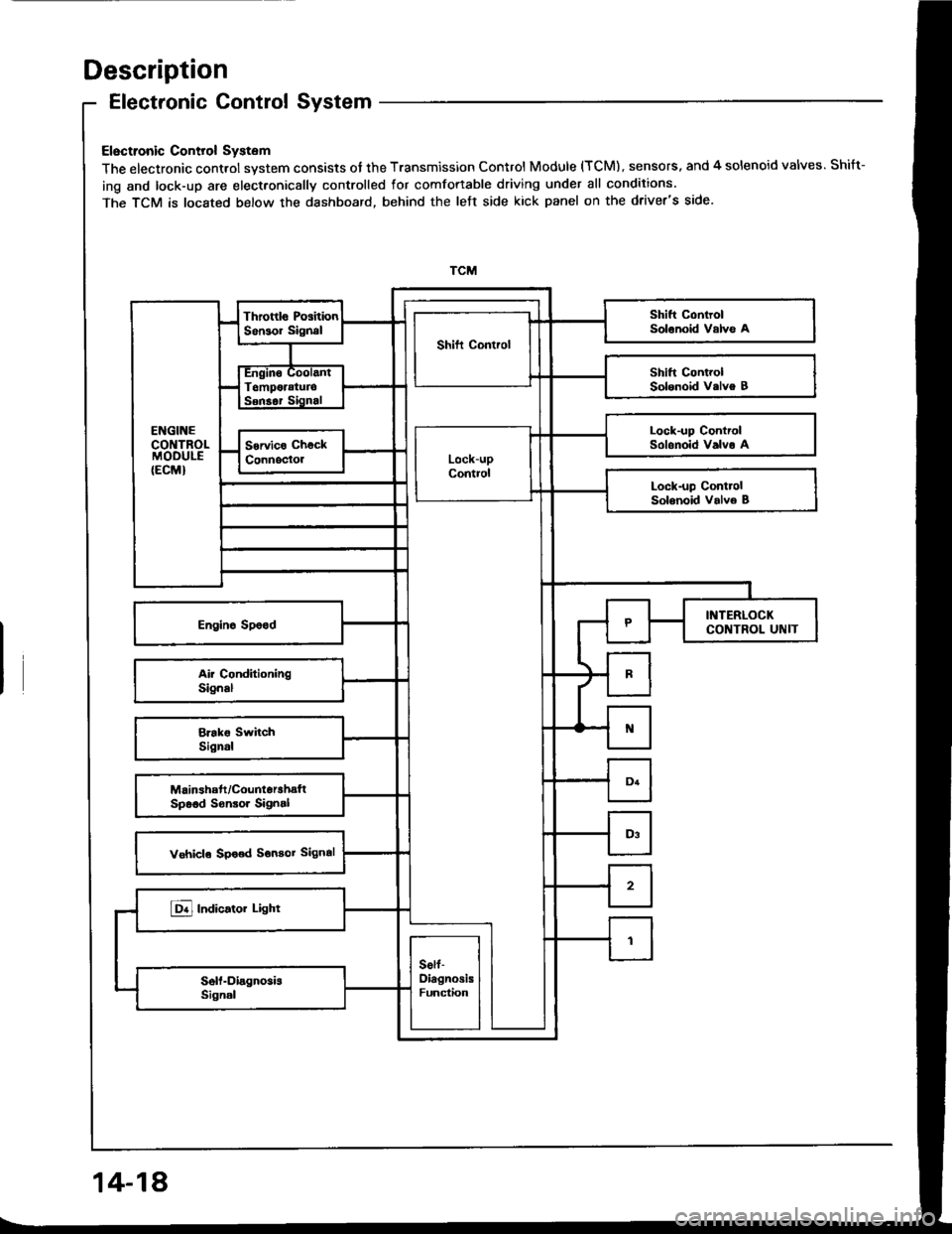
Electronic Control System
Electronic Control System
The electronic control system consists of the Transmission Control Module (TCM), sensors. and 4 solenoid valves. Shift-
ing and lock-up are elect.onically controlled for comfortable driving under all conditions.
The TCM is located below the dashboard, behind the left side kick panel on the driver's side.
Lock-up ControlSolonoid Valvo A
14-18
Page 440 of 1413
![HONDA INTEGRA 1994 4.G User Guide Troubleshooting Procedures
when the TcM senses an abnormality in the input or output systems. the E]indicator light in the gaugo assembly willblink.
when the service check Connector {located under the HONDA INTEGRA 1994 4.G User Guide Troubleshooting Procedures
when the TcM senses an abnormality in the input or output systems. the E]indicator light in the gaugo assembly willblink.
when the service check Connector {located under the](/img/13/6067/w960_6067-439.png)
Troubleshooting Procedures
when the TcM senses an abnormality in the input or output systems. the E]indicator light in the gaugo assembly willblink.
when the service check Connector {located under the dash on the passenger side} is connected with the specaat toolas shown, the E] indicator light will blink the Diagnostic Trouble iode {DTCI when the ignition switch is turned on.
When the lDil indicator light has been reported on, connect the service check connector with the special tool.Then turn on the ignition switch and observe the @ indicator light.
GAUGE ASSEMSLY
)'t
DAI'A LI]TKcor{r{EcToR (3P)NOTE:Do not atlachjumpe. wire.
Sc. DTCI
So. DTC2
S.. DTC14
scs sHoRT CO[{]{ECTORoTPAZ-OOl0too
codes 1 through I are indicated by individual short blinks, codes 1o through 1 5 are indicated by a series of tong andshon blinks. one long blink equals l0 short blinks. Add the long and short blinks together to dete;mins the cod€. Aft6rdetermining the code, refer to the erectricar system symptom-to-component chart on pages 14-5o and 51.
ahon
f"l
some PGM-FI problems will also make the @ indicator light come on. After repairing the pGM-Fr system, disconnectthe BACK UP tuse (7.5 Al in the under-hood fuse/relay box tor more than 1o seconds to reset the TcM memorv.
NOTE:
a PGM-FI svstem
The PGM-FI system on this model is a sequential multipon fuel iniection svstem.' Disconnecting the BACK UP tuse also cancels the radio anti-theft code, preset stations and the clock setting. G6tthe customer's code numbe. and make note of the radio presets befote temoving the fuse so you can reset them.
14-48
Page 476 of 1413
Transmission Control Module
Replacement
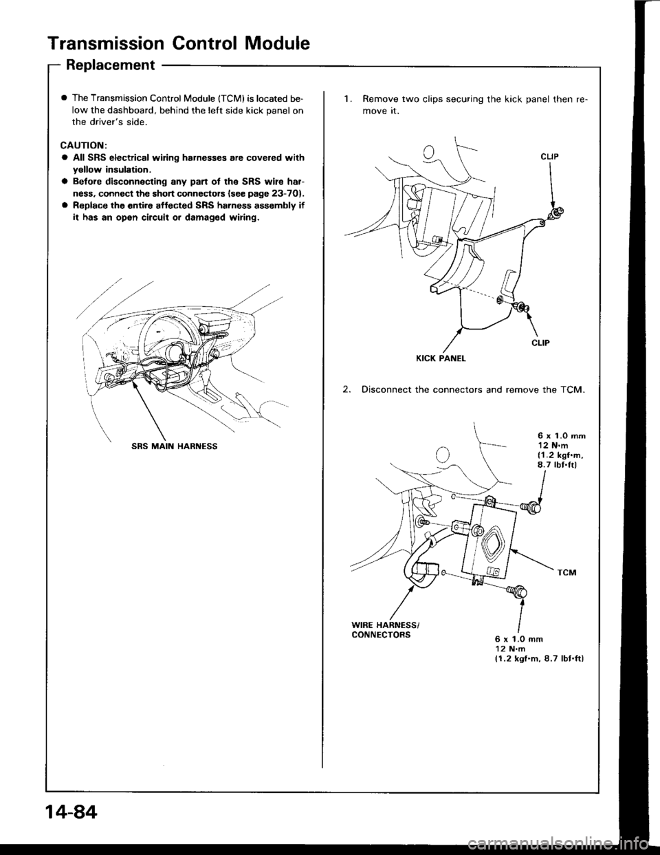
I The Transmission Control Module (TCMI is located be-
low the dashboard, behind the lelt side kick panel on
the driver's side.
CAUTION:
a All SRS electrical wiring hahesses are covered withyellow insulation.
a Betore disconnecting any pan ot the SRS wile har-
ness. connect the short connectors lsee page 23-7O).
a Replace the entir6 affected SRS harness ass€mbly if
it has an open circuit or damaged wiring.
1. Remove two clips securing the kick panel then
move it.
2. Disconnect the connectors and remove the TCM.
6 x 1.0 mm12 N'm{1.2 kgf.m,8.7 tbf.Itl
WIRE HARNESS/CONNECTORS6 x 1.0 mm12 N.m(1.2 kgf.m, 8.7 lbt.ftl
KICK PANEL
SRS MAIN HARNESS
14-84
Page 608 of 1413
Steering
Special Tools ............. 17-2
Component Location
lndex ................ ...... 17-3
System Description
Ff uid Flow Diagram ......................... 17 -1
Steering Pump ................................. 17-5
Steering Gearbox ............................. 17-7
Troubleshooting
General Troubleshooting ................ 17-10
Noise and Vibration ......................... 17-14
Fluid Leaks ............. 17-16
Inspection and Adiustment
Steoring Operation .......................... 17 -14
Power Assist Check
with Car Parked ........................... 17-18
Steering Linkage and Gearbox ....... 17-19
Pump Beh .............. 17-20
Rack Guide Adjustment ............. ..... 17-21
Ff uid Replacement ...................... ..... 17 -21
Pump Pressure Check .................. .... 17 -22
Ffuid Leakage lnspection ................ 17-23
+ Steering Wheel
Removal ..,,,,,,,........ 17-24
Disassembly/Reassembly ............... 17 -25
fnstallation ,......,,,,,. 17-26
* Steering Column
Removaf .................17-28
Inspection .............. 17-30
Installation ............. 17-31
Power Steering Hoses. Pipes
Replacemont ......... 17-3tl
Power Steering Pump
Removal ................. 17-35
Disassembly .......... 17-35
Reassembly ........... 17-'10
lnstallation ........,..., l7-tltl
Steering Gearbox
Removaf .,.,............. 17-45
Disassembly .......... 17-/E
Reassembly ........... 17-53
lnstallation ............. 17-63
Ball Joint Boot Replacement .......... 17-65
SUPPLEMENTAL RESTRAINT SYSTEM {SRSI
The Integra SRS includes a driver's airbag. located in the steering wheel hub, In addition, all models except the
RS model for Canada have a front passenger's airbag located in the dashboard above the glove box. Information
necessarv to safely service the SRS is included in this Service Manual. ltems marked with an asterisk {') on the
contents page include, or are located near, SRS components. Servicing. disassembling or replacing these items
will require special precautions and tools, and should therefore be done by an authorized Acura dealer.
a To avoid rsndering ths SRS inoporative, which could load to po.sonal iniury 01 d€ath in th€ event ot a ssvare
lrontal collision, all SRS service work muat be performod by an authorizod Acura deal6t.
a lmploper service procodules. including incorloct romoval and installation of the SRS, could lead to personal iniu-
ry caused by unintontional activation ot the airbags.
a All SRS elsctdcal wiring harnesses ara covorod with ysllow insulation. Rolalod compon€nts 8re locatsd in tho
stse ng column, tront console, dashboard, and dashboard lower panel, and in the dashboard above the glove
box. Do not use oloctrical tost equipmoni on thosa cilcuits.
NOTE: The original radio has a coded thett protection circuit. Be sure to get the customer's code number before
- disconnecting the battery.- removing the No. 32 (7.5 A) tuse from the under-hood fuse/relay box.
- removing the radio.
Alter service, reconnect power to the radio and turn it on. When the word "CODE" is displayed' enter the cus-
tomer's 5-digit code to restore radio operation.
Page 636 of 1413
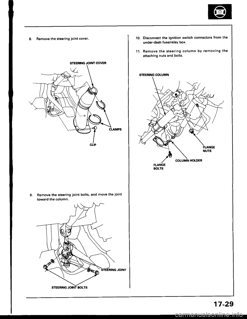
8. Remov€ the stesring ioint cover.
Remove tho steering joint bolts, and move the ioint
toward ths column.
JOIMT OOVER
STEERING COLUMN
BOITS
10.
'l1.
Disconnoct the ignition switch connectors from th6
undor-dash fuse/relav box.
Remove tho steering column by removing the
attaching nuts 8nd bolts.
17-29
Page 640 of 1413
7.
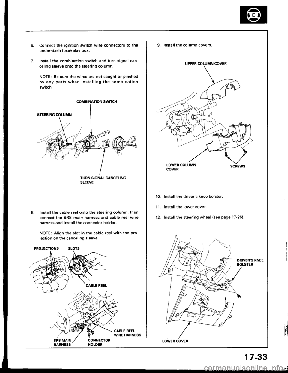
Connect the ignition switch wire connectors to the
under-dash fuse/relav box.
Install the combination switch and turn signal can-
celing sleeve onto the steering column.
NOTE: Be sure the wires are not caught or pinched
by any parts when installing the combination
switch.
TURN SIGNAL CANCELINGSLEEVE
Install the cable reel onto the steering column, then
connect the SRS main harness and cable reel wiro
harness and install the connector holder.
NOTE: Align the slot in the cable reel with the pro-
jection on the canceling sleeve.
coMatNATroN swncH
UPPER COLUMN COVER
9. Installthe column covers.
scREws
lnstall the driver's knee bolster.
lnstall the lower cover.
Installthe steering wheel {see page '17-26).
10.
11.
't2.
17-33