ESP HONDA INTEGRA 1994 4.G User Guide
[x] Cancel search | Manufacturer: HONDA, Model Year: 1994, Model line: INTEGRA, Model: HONDA INTEGRA 1994 4.GPages: 1413, PDF Size: 37.94 MB
Page 486 of 1413
Pressure Testing
a While testing, be caretul of the rotating flont wheels.a Make aura litts, jacks, and sat€ty stands alo placedplop6rly {see section 1}.
CAUTION: Betore t€sting, be sure the transmission fluidis tilled to rh6 ploper l€vet.
1. Raise the car (see section i),
2. Warm up the engine {the cooling fan comes onl, thenstop the engine and connect a tachometer.
3. Connect the oil pressure gauge to each inspectionholels).
TOROUE: 18 N.m (1.8 kgf.m, 13 tbf.fr)
CAUTION: Connect ths oil prsssure gauge s€cur€_ly; be sule not to allow dust and other foleign pani_cl6s to 6nt€1 th€ inspection holo.
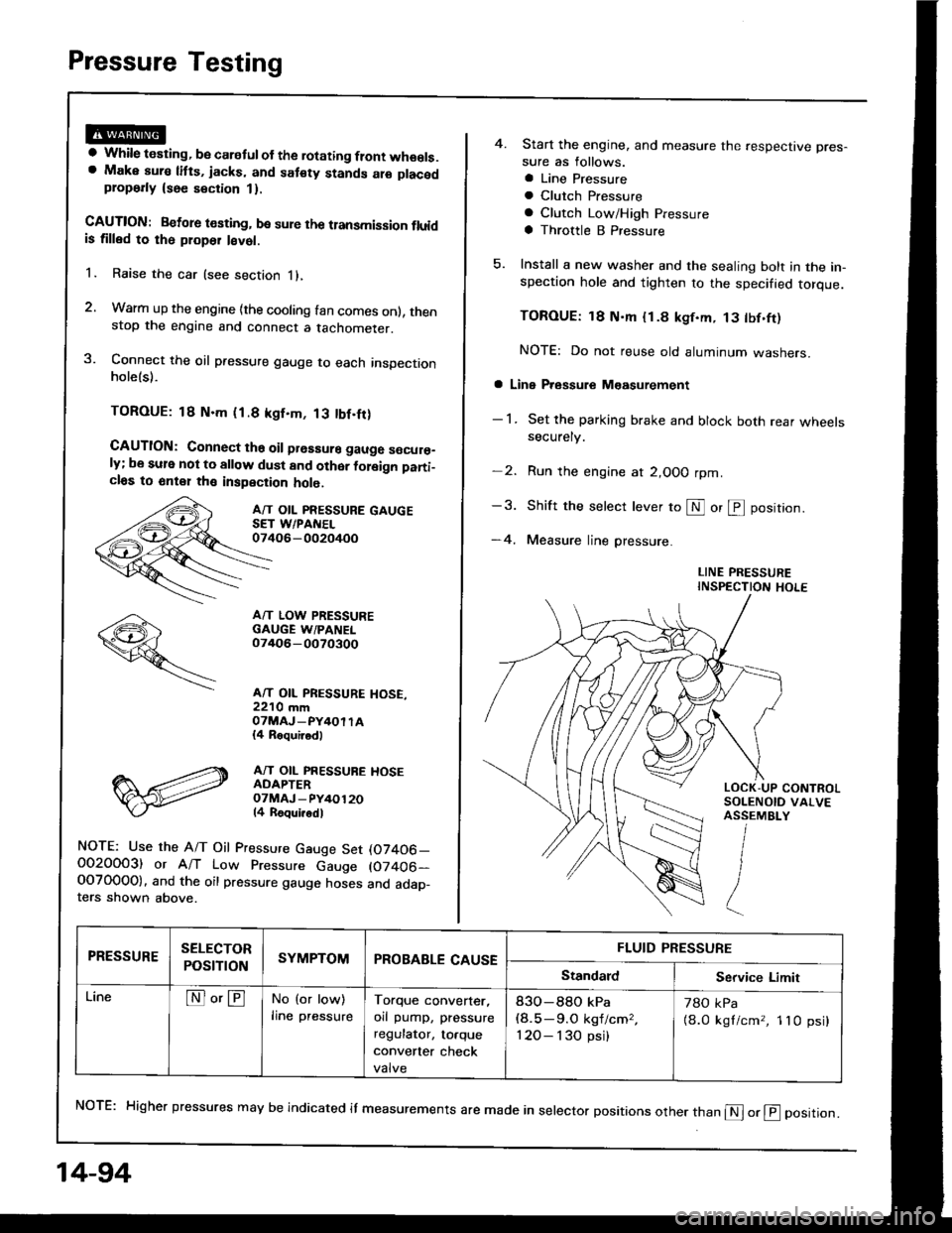
A/T OIL PRESSURE GAUGESET WPANEL07406-002oi+oo
A/T LOW PRESSUREGAUGE W/PANEL07/rO6-0O70300
A/T OIL PRESSURE HOSE,22'10 mmOTMAJ_PY4OI TA{4 Roquirod)
A/T OIL PRESSUBE HOSEADAPTEROTMAJ - PY/+O12014 Roqui.odl
NOTE: Use the A/T Oil Pressure Gauge Set (07406_O02OOO3) or A/T Low Pressure Gauge (07406-OOTO0OO). and the oil pressure gauge hoses and adap_ters shown above.
14-94
4. Start the engine, and measure the respective pres-
sure as follows.
a Line Pressure
a Clutch Pfessure
a Clutch Low/High Pressure
a Throttle B Pressure
5. Install a new washer and the sealing bolt in the in-spection hole and tighten to the specified torque.
TOROUE: 18 N'm {1.8 kgf.m, 13 tbf.ft)
NOTE: Do not reuse old aluminum washers.
a Line Pressure M€asurement
- 1 . Set the parking brake and block both rear wheelssecurely.
-2. Run the engine at 2,OOO rpm
-3. Shift the selecr lever to S or @ position.
-4. Measure line pressure.
LINE PRESSUREINSPECTION HOLE
NoTE: Higher pressures may be indicated it measurements are made in selector positions other than @ or @ position.
PRESSURESELECTOR
POStTTONSYMPTOMPROBABLE CAUSEFLUID PRESSURE
StandardService Limit
LineNo'ENo (or low)
lrne pressureTorque converter,
orl pump, pressure
regulator, to.que
convener check
valve
83O-88O kPa(8.5-9.O kgf/cm,,
120- I 30 psi)
78O kPa
{8.0 kgl/cm,, 1lO psi}
Page 509 of 1413
Valve
Assembly
NOTE:
Coat all parts with ATF belore assemblv.
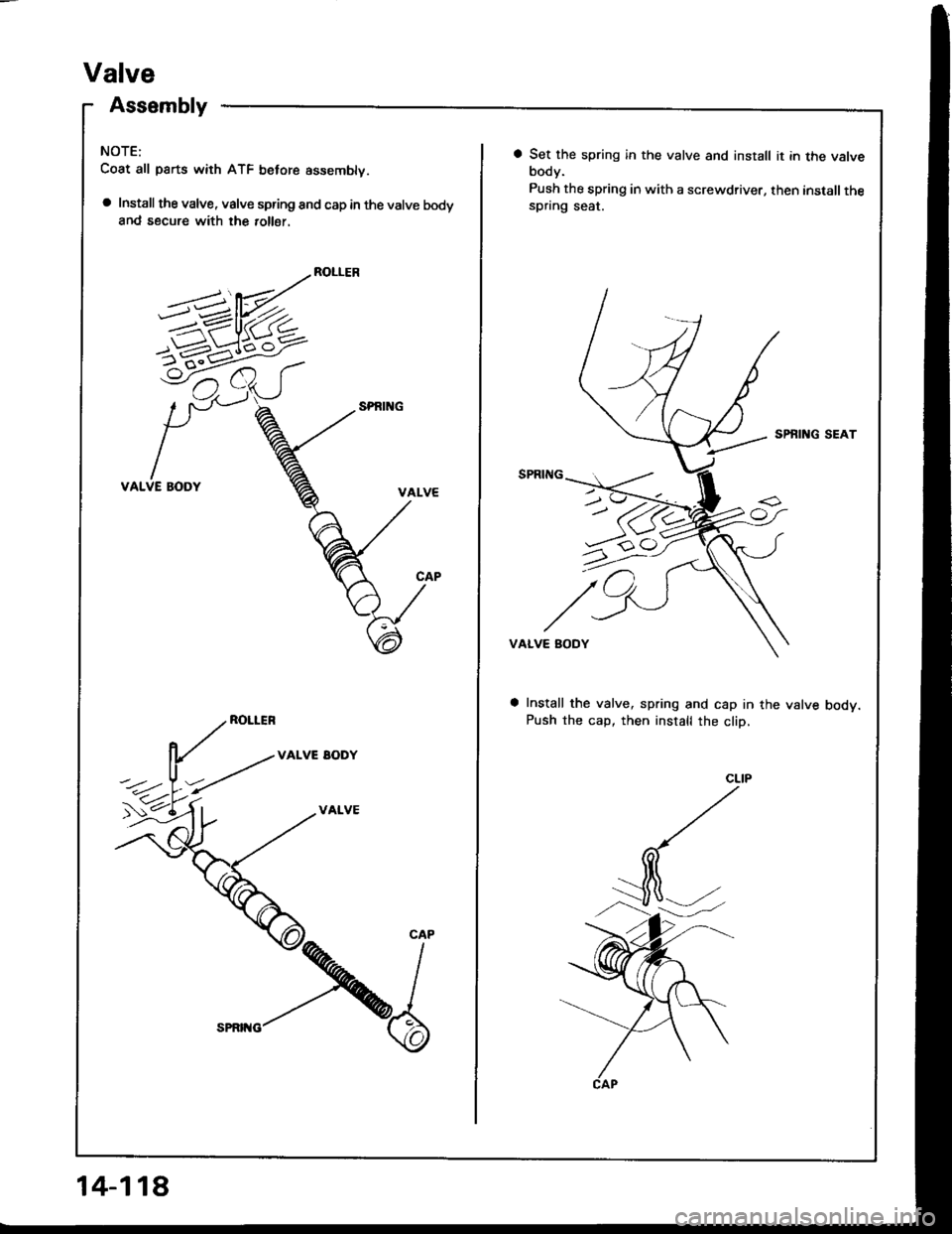
a Install the valve, valve spring and cap in the valve bodyand secure with the 10116r.
ROLLER
VALVE BODY
ROLLER
VALVE EODY
VALVE
5-1-6^<
CAP
14-118
a Set the spring in the valve and install it in the valvebody.
Push the spring in with a screwdriver, then installthespring seat.
SPBING SEAT
VALVE BODY
Install the valve, spring and cap in the valve bodv.Push the cap, then install the cliD,
Page 543 of 1413
Transmission Housing Bearings
Mainshaft/Countershaft Bearing Replacement
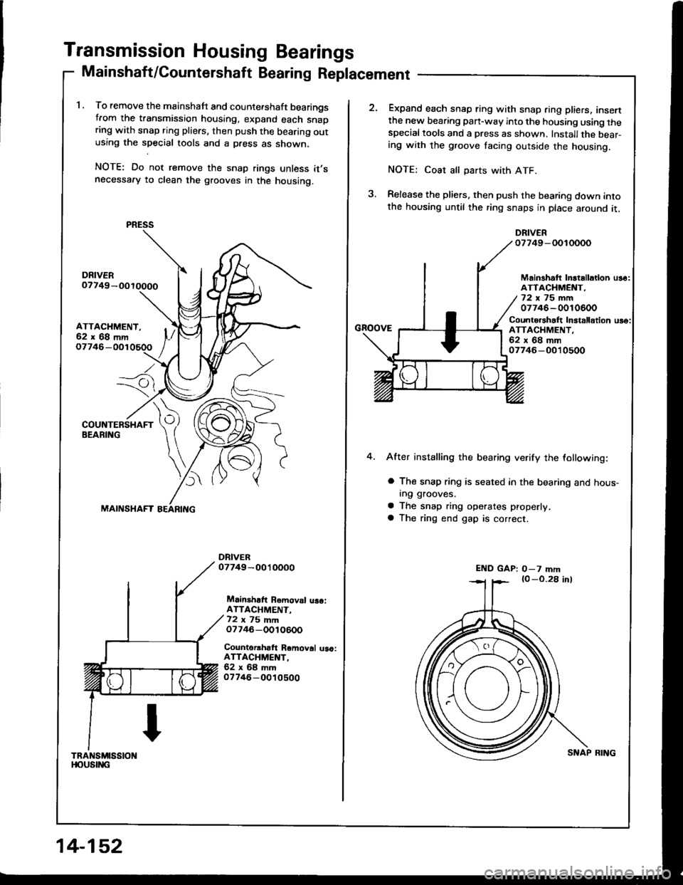
1. To remove the mainshaft and counte.shaft bearingstrom the transmission housing, expand each snapring with snap ring pliers, then push the bearing outusing the special tools and a press as shown,
NOTE: Do not remove the snap rings unless it,snecessafy to clean the grooves in the housing.
ATTACHMENT,62x68mm
Io7746-
---7i
)
MAINSHAFT
Mainshaft Removal uaoiATTACHMENT-72 ,, 75 mmo7746-OOlO600
Counterrhaft Removal uao:ATTACHMENT,62x68mm07746-O010500
TRANSMISSIONt|oustitc
PRESS
14-152
SNAP BING
Expand each snap ring with snap ring pliers, insertthe new bearing pan-way into the housing using thespecialtools and a press as shown. Installthe bear-ing with the groove tacing outside the housing.
NOTE: Coat all parts with ATF.
Release the pliers. then push the bearing down intothe housing until the ring snaps in place around it,
DRIVERo7749-OOIOOOO
GnoovE
Mainshatt Inltallation us6:ATTACHMENT,72x75mm07746-0010600
Counto.shalt In3talldtion uso:ATTACHMENT.62x68mm07746-O010500
4.After installing the bearing verify the lollowing:
a The snap ring is seated in the bearing and hous-In9 grooves.
a The snap ring operates properly
a The ring end gap is correct.
END GAP: O-7 mm
Page 612 of 1413
Construetion
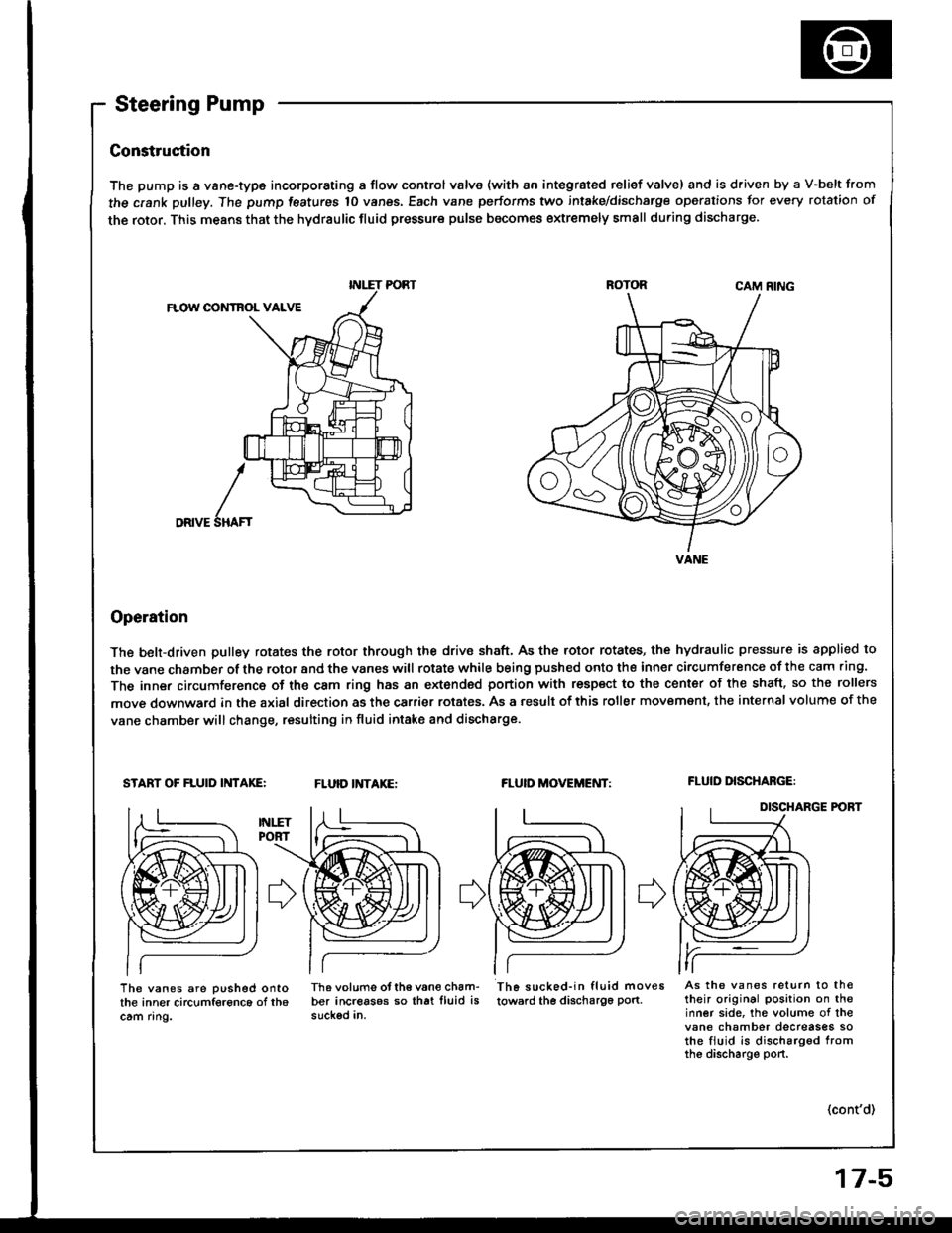
The pump is a vane-type incorporating a flow control valve (with an integrated relief valve) and is driven by a V-belt from
the crank pulley. The pump features 10 vanes, Each vane performs two intake/dischsrge operations for every rotation of
the rotor. This means that the hydraulic fluid pressure pulse becomes extremely small during discharge.
CAM RING
FLOW CONTBOL VALVE
DRIVE
Operation
The belt-driven pulley rotates the rotor through the drive shaft, As the rotor rotates, the hydraulic pressure is applied to
the vane chamber of the rotor and the vanes witl rotate while being pushed onto the inner circumference of the cam .ing.
The inner circumference of the cam ring has an extonded portion with respect to the center of the shaft. so the rollers
move downward in the axial direction as the carrier rotates. As a result of this roller movemsnt, the internal volume of the
vane chamber will change, resulting in fluid intake and discharge.
START OF FLUID INTAKE:FLUID INTAKE:FLUID MOVEMENT:FLUID DISCHABGE:
DISCHARGE P('BT
I
SHAF'
The vanes are pushed ontothe inner circumference of th6cam ring.
Th6 volums otth€ van€ cham-ber increasos so that lluid issuckod in.
Th6 sucked-in fluid moves
towsrd the discha196 pon.As the vanes return to th€their original position on theinner side, the volume of thevane chamber decreases sothe fiuid is discharg6d fromthe discharge port.
(cont'd)
INLET PORT
VANE
Page 615 of 1413
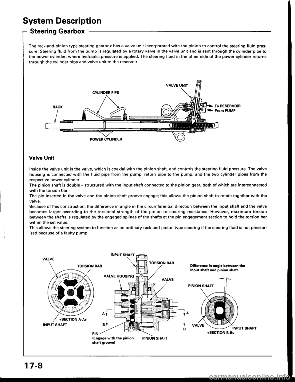
System Description
Steering Gearbox
The rack-and-pinion type steering gearbox has a valve unit incorporated with the pinion to control the steering fluid pres-
sure. Steering fluid from the pump is regulated by a rotary valve in the valve unit and is sent through the cylinder pipe to
the power cylinder, where hydraulic pressure is applied. The steering fluid in the other side of the power cylinder returns
through the cylinder pipe and valve unit to the reservoir.
VALVE UNIT
CYLINDER PIPE
POWEB CYLINDER
Valve Unit
Inside the valve unit is the valve, which is coaxial with the pinion shaft, and controls the steering fluid pressure. The valve
housing is connected with the fluid pipe from the pump, return pipe to the pump, and the two cylinder pipes from the
respective power cylinder.
The pinion shaft is double - structured with the input shaft connected to the pinion gear, both of which are interconnected
with the torsion bar.
The pin insened in the valve and the pinion shaft groove engage; this allows the pinion shaft to rotate together with the
Because of this construction, the difference in angle in the circumferential direction between the input shaft and the valve
becomes larger according to the torsional strength of the pinion or steering resistance. However, maximum torsion
between the shafts is regulated by the engaged splines of the shafts at the pin engagement section to hold the torsion bar
within the set value.
This allows the steering system to lunction as an ordinary rack-and-pinion type steering if the steering fluid is not pressur-
ized because of a faulty pump.
VALVE
Difforcnco in .ngl. bo{w€cn thainput shalt rnd pinion !h.tt
ln-1
B
lEngag€ with the pinionshaft groove)
17-8
INPUT SHAFT
Page 620 of 1413
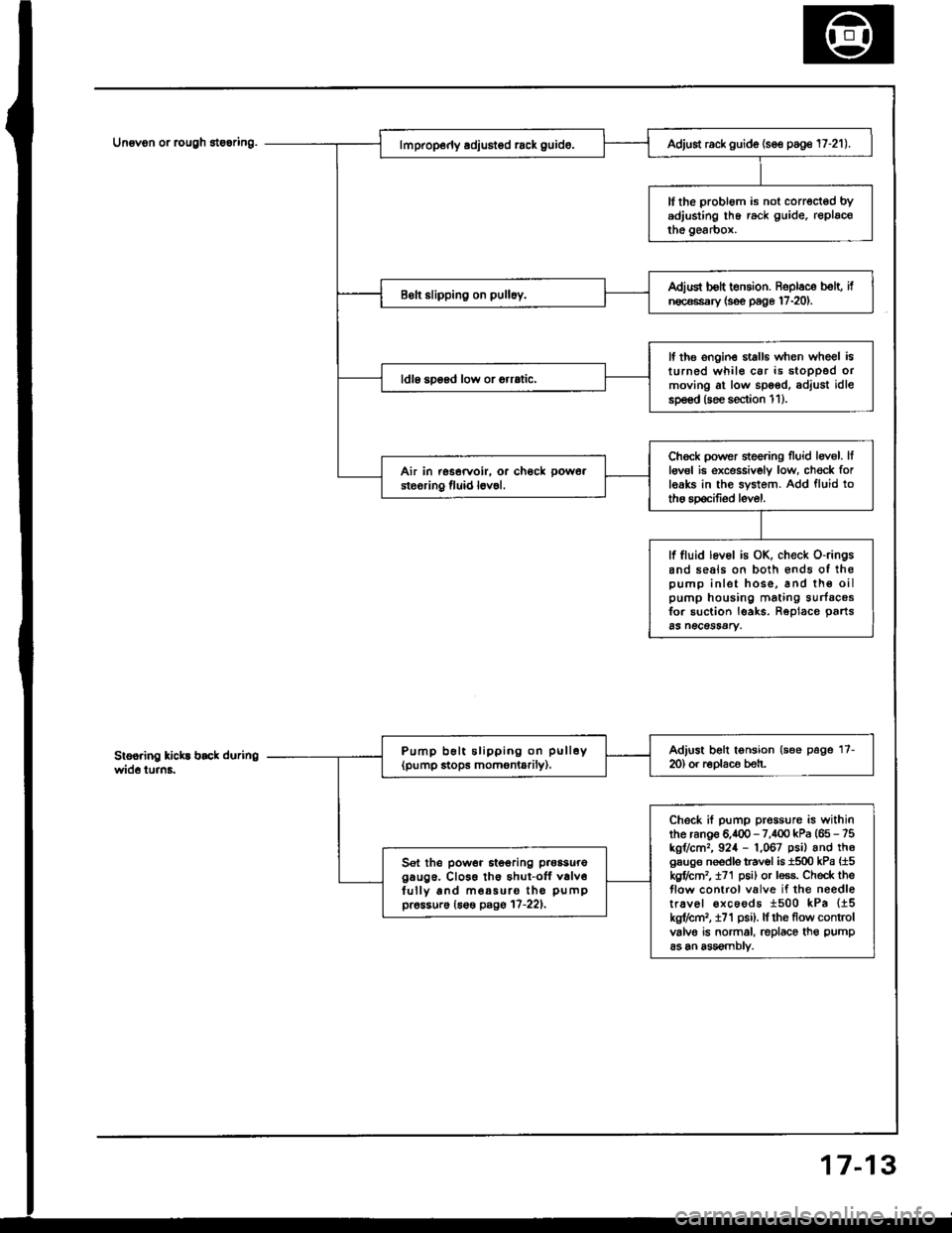
Unovon or rcugh 8te6ring.
3
Adjust rack guide (se€ poge 17-21).
ll the probl6m is not corrected bYadjusting lhe rack guide. replacothe gearbox.
Adiud bolt t€nsion. Roplace b€lt, ifn€c€ssary {s€e page 17-20).
lf the ongin€ stalls when wheel isturned whil€ car is stoDPed ormoving at low spoed, adjust idlesp€€d (soe section 1 1 ).
ldl6 soosd low or orrrtic.
Chock power sieering Iluid levol. Itlgv6l ie excessivoly low, ch€ck forleaks in the system. Add fluid totho spocifiod level.
Air in rssorvoir. or ch€ck pow6a
steoring fluid l6v6l.
lf fluid lev6l is OK, check o-ringsand seals on both €nds of ihopump inlet hose, and th€ oilpump housing mating surfacosfor suction leaks. Reolace oarts65 n€CeSSAry.
Adjust belt tonsion (see page 17-m) or r€Dlaco beh.Pump b6lt slipping on pull6y(pump stops momontarily).
Check if pump prossure is withinthe ranoe 6.400 - 7,100 kPa (65 - 75kgr/cm,, 924 - 1,067 psil and th6gsuge needls travol is 1500 kPa {15kgflctn2, t71 p6i) or less. Check theflow control valve if the needletr.vel €xcoods 1500 kPa {15kg?cm,, i71 psi). lf rhe flow controlvalvo is normal, replace th€ pump
as an assomblv.
Sel the power itooring p.oasuregaug6. Cl066 th€ shut-off v6lv6fully and m€a5uro tho pumppr6ssur6 (6s€ pagg 17-221,
7-1
Page 641 of 1413
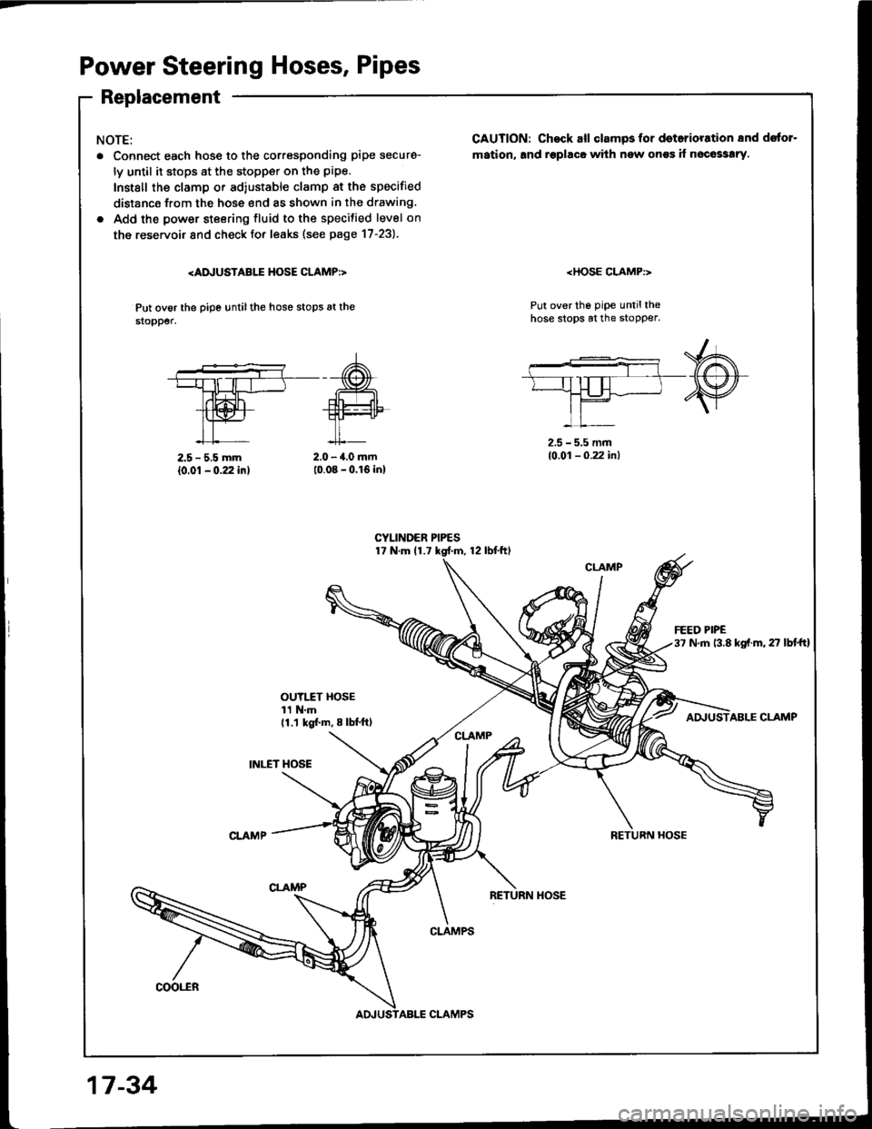
Power Steering Hoses, Pipes
Replacement
NOTE:
. Connect each hosg to the corresponding pipe securg-
ly until it stops at the stopp€r on the pipe.
Install the clamp or ad,ustable clamp at the specified
distancs from the hose end as shown in the drawing.
. Add the power steering fluid to the specilied level on
the reservoir and check fo. leaks (see page 17-23).
Put ov6r the pipe untilthe hose stops at the$opper.
CAUTION: Chock all clampsfor doterioration 8nd dstor-
mation, and rsplacG with new onss if n6co33!ry,
Put over the pipe untilthehose stops at the stopper.
2.5 - 5.5 mm
{0.01 - 0.22 inl2.0 - 4.0 mm10.08 - 0.16 inl
2.5 - 5.5 mm10.01 - 0.22 in)
OUYI.fT HOSE11 N.m{1.1 kgl.m, 8 lbl.ftl
INI."ET HOSE
ABLE CLAMP
RETURN HOSE
coot"ER
CLAMPS
17 -34
CLAMPS
Page 644 of 1413
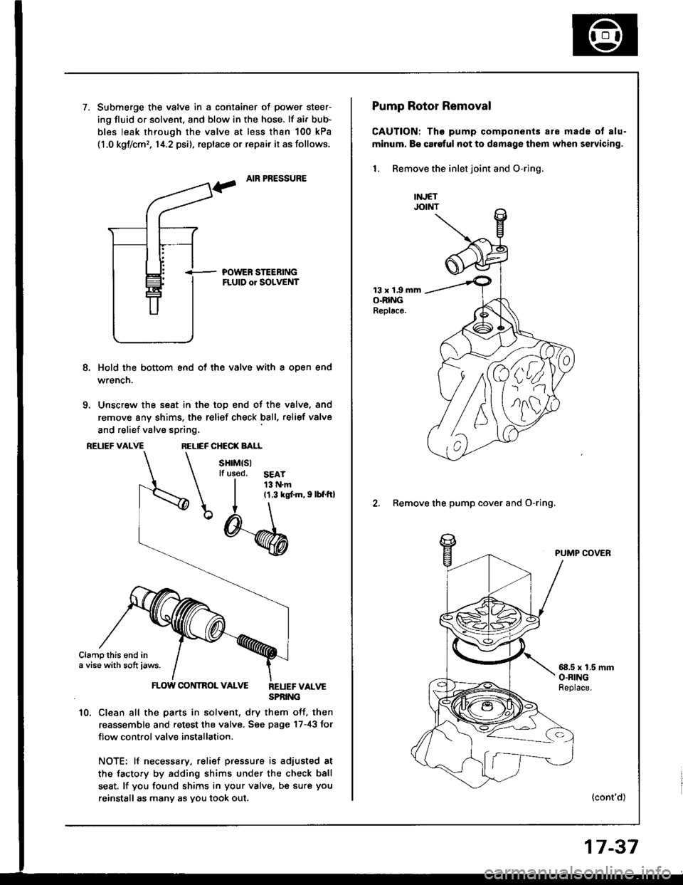
7.Submerge the valve in a container of power steer-
ing fluid or solvent, and blow in the hose. lf air bub-
bles leak through the valve at less than 100 kPa
11.0 kgf/cm,, 14.2 psi), replace or repair it as follows.
AIR PRESSURE
i- POWER STEEBINGFLUID or SOLVENT
8, Hold the bottom end of th€ valve with a oDen end
wrencn.
9. Unscrew the seat in the top end of the valve, and
remove any shims, the relief check ball, relief valve
and relief valve spring,
REUEF VALVERELIEF CHECK BALL
sHrM(sllf us€d.SEAT13 N.m11.3 ks[.m, I lbf.tt]
Clampthis end ina vise with sott iaws.
FLOW CONTROL VALVE REUEFvALvESPBING
10. Clean all the parts in solvent, dry them off, then
reassemble and retest the valve. Sge page 17-43 for
f low control valve installation.
NOTE: lf necessary, relief pressure is adiusted at
the facto.y by adding shims under the check ball
seat. lf you found shims in your valve, be sure you
reinstall as many as you took out,
')4.
nlll
Pump Rotor Removal
CAUTION: Tho pump components are made ot alu-
minum. B€ car6ful not to damage them when servicing.
1. Remove the inlet joint and O-rjng.
13 x 1.9 mmO.RINGReplac€.
2. Remove the pump cover and O-ring.
PUMP COVER
58.5 x 1.5 mmO.RINGFeplace.
(cont'd)
17-37
Page 666 of 1413
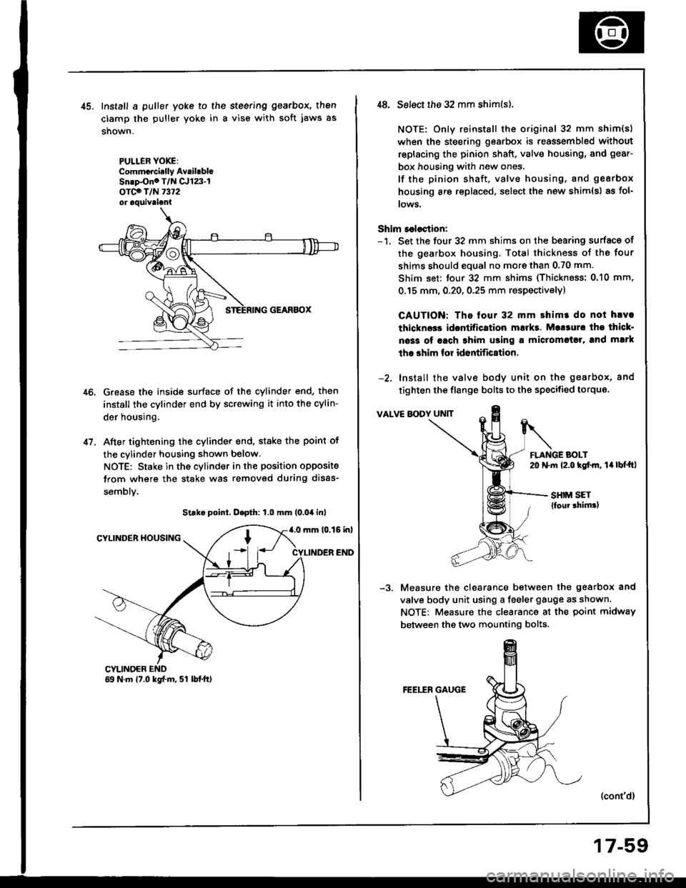
41.
Install a puller yoke to the steering gearbox, then
clamp the puller yoke in a vise with soft jaws as
shown.
PULLER YOXE:Commcrcirlly AvrihbloSn.p-Ono T/N Cr123-lorco T/N 7372or aquivrlani
Grease the inside surface of the cylinder end, then
install the cylinder end by screwing it into the cylin-
der housing.
After tightening the cylinder end, stake the point of
the cylinder housing shown below.
NOTE: Stake in the cylinder in the position opposite
from where the stake was removed during disas-
semblv.
Strke point, D.pth: 1.0 mm (0.04 inl
4.0 mm 10.15 inlCYLINDER HOUSING
CYLINDER END
CYLINOER69 N.m 17.0 kgf.m, 51 lbtft)
,t8. Select the 32 mm shim(s).
NOTE: Only reinstall the original 32 mm shim(s)
when the steering gearbox is reassembled without
replacing the pinion shaft, valve housing, and gear-
box housing with new ones.
lf the pinion shaft, valve housing, and gearbox
housing are replaced, select the new shim{s) as fol-
rows.
Shim r€lection:-'1. Set the four 32 mm shims on the b€aring surface of
the gearbox housing. Total thickness of the four
shims should eoual no more than 0.70 mm.
Shim set: tour 32 mm shims (Thickness: 0.10 mm,
0.15 mm, 0.20, 0.25 mm respectivelyl
CAUTION: The tour 32 mm shimr do not hlva
thlckn$s idcntitication mukt. Mo!3ur. tho thicl-
oa33 of rach 3him using a miclomctrl, and mlrk
tho shim lor id6ntific8tion.
-2. Install the valve body unit on the gearbox, and
tighten the flange bolts to the specitied torque
VALVE BODY UNIT
FLANGE BOLT20 N.m {2.o kgtm, 14lbt'ftl
SHIM SET{foul thim.)
Measure the clearance between the gearbox and
valve body unit using a feeler gauge as shown.
NOTE: Measure the clearance at the point midway
between the two mounting bolts.
(cont'd)
17-59
Page 931 of 1413
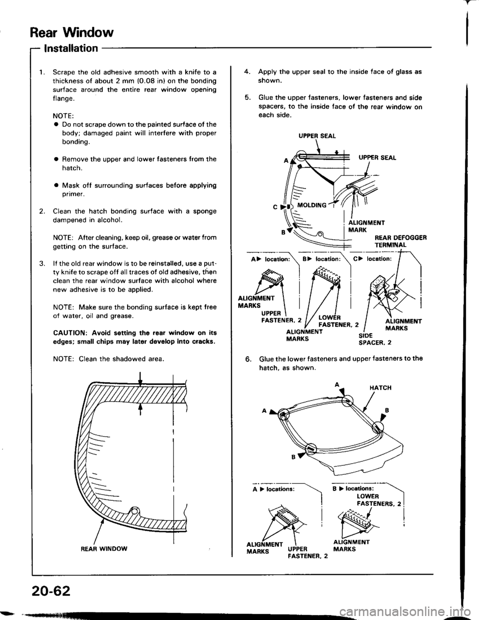
Rear Wndow
-r
lnstallation
Scrape the old adhesive smooth with a knife to a
thickness of about 2 mm (O.O8 in) on the bonding
surface around the entire rear window opening
flange.
NOTE:
a Do not scrape down to the painted surface of the
body; damaged paint will interfere with proper
bonding.
a Remove the upper and lower fasteners trom the
hatch.
a Mask otf surrounding surtaces before applying
primer.
Clean the hatch bonding surface with a sponge
dampened in alcohol.
NOTE: After cleaning, keep oil, grease or water trom
getting on the surface.
lI the old rear window is to be reinstalled, use a put-
ty knile to scrape ott all traces ot old adhesive, then
clean the rear window surface with alcohol where
new adhesive is to be applied.
NOTE: Make sure the bonding surface is kept tree
of water, oil and grease.
CAUTION: Avoid s€tting ths rear window on its
edges; small chips may lator devalop into cracks,
NOTE: Clean the shadowed area,
REAR WINDOW
20-62
---
UPPER SEAL
4.Apply the upper seal to the inside face of glass as
snown.
Glue the upper tasteners, lower fasteners and side
spacers, to the inside tace ot the rear window on
each side.
FASTENER,2' / FASTENER,2ALIGNMENT
G||le the lower fasteners and upper Jasteners to the
hatch, as shown.
sroESPACER, 2