Rear Window
lnstallation (cont'd)
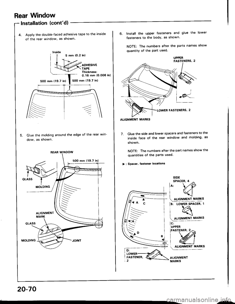
4. Apply the double-faced adhesive tape to the inside
o{ the rear window, as shown
Glue the molding around the edge oi the rear win-
dow, as shown.
5OO mm 119.7
MOLDING
lnside
0.16 mm (0.006 inl
500 mm (19.7 in)5OO mm 119.7 in)
MOLDING
ALIGNMENT MARKS
6. Install the upper fasteners and glue the lower
fasteners to the bodY, as shown.
NOTE: The numbers atter the parts names show
quantity of the Part used.
7. Glue the side and lower spacers and tasteners to the
inside face ot the rear window and molding, as
shown.
NOTE: The numbers after the part names show the
quantities of the Parts used.
> : Spac6r, lastonel locations
SIDESPACER,4 ^
lo, \./O
lq
4!9!llEN,r_r\,ry!s
la, Loqrcen.t
(4relycv!|I!"
l$;*
\'*'w
o.f9!T.nl "1"*"
ALIGNMENTMARKS
'7:^ c
rs
--
s-."
20-70
"-
Troubleshooting
Tips and Precautions (cont'dl
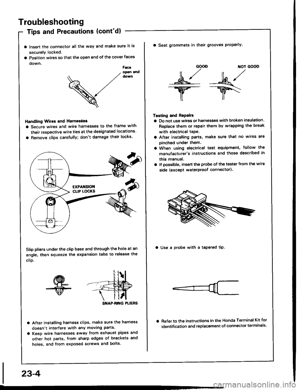
a lnsert the connector all the way and make sure it is
securely locked.
a Position wires so that the open end of the cover taces
down.Facaopon andcown
V
Handling Wir€s and Hamorao8
a Secure wires and wile harnesses to the frame with
their respective wire ties at the designated locations'
a Remove clips carefully; don't damage their locks'
Stip pliers under the clip base and through the hole at an
angle, then squeeze the expansion tabs to release the
clio.
SI'IAP-ANG PLIERS
a After installing harness clips, make su.€ the hatness
doesn't interfe.e with any moving parts.
a Keeo wire hatnesses away from exhaust pipes and
other hot parts, ftom sharp edges of brackets and
holes, and from exposed screws and bolts.
23-4
GOOD ]TOT GOOD
n,/r/ll ,,' ll ,,
s*j -:ut*/-.w-- --ry\
il,,
Tosting and Ropails
a Do not us€ wires or harness€s with broken insulation.
Replace them or repair them by wrapping th€ break
with electrical tape.
a After installing pans, make sure that no wir€s are
Dinched undsr them.
a When using electrical test €quipment, follow the
manufacturer's instructiona and those dsscribed in
this manual,
a It possible, insert the probe of the toster from the wire
side {except waterproof connector).
a Seat grommets in theil grooves properly.
a Use a probe with a tapered tip.
Refer to the instructions in the Honda Terminsl Kit for
identification and .eplacement o{ connector telminals'
lgnition Coil Test
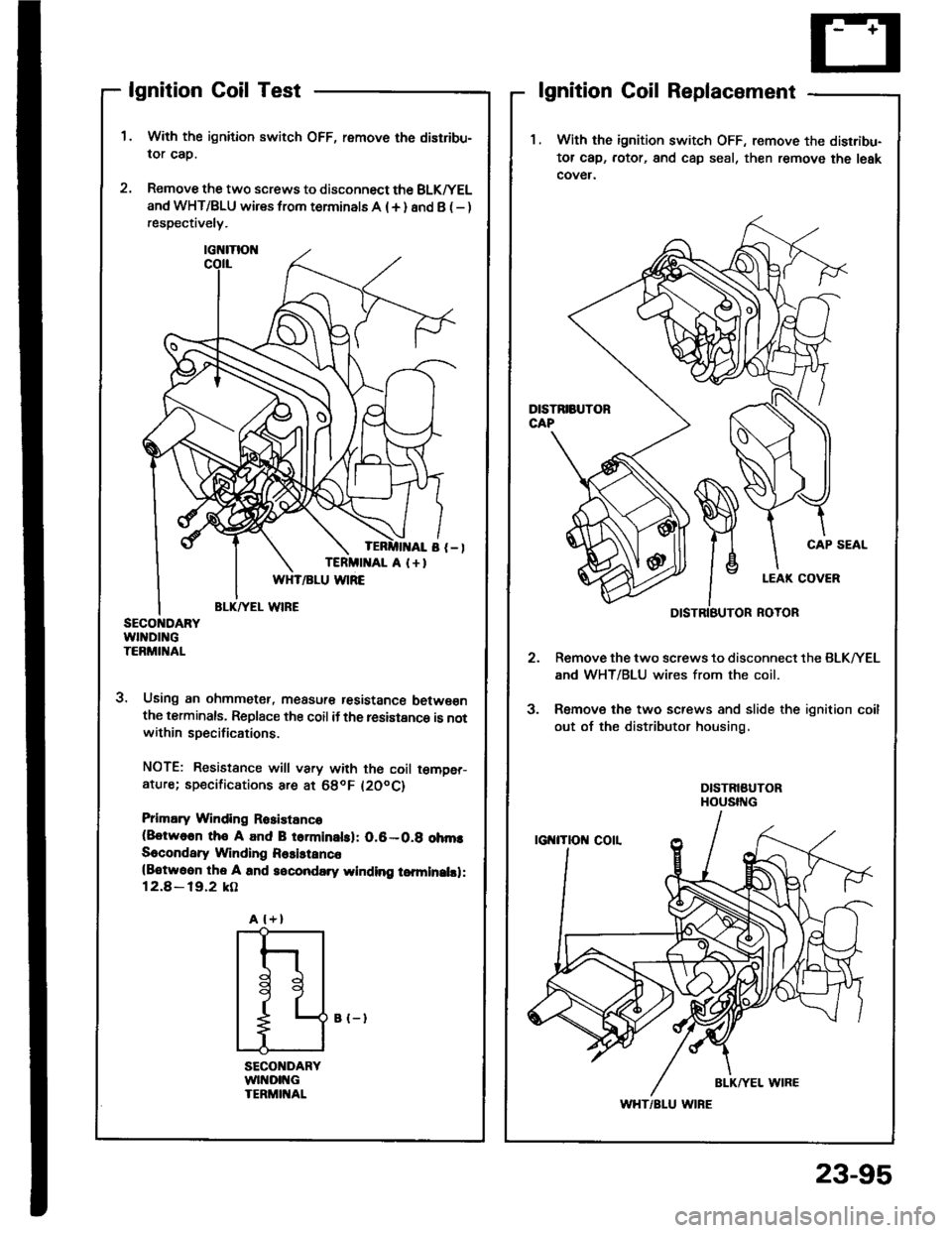
With the ignition switch OFF, remove the distribu-
lor cap.
Remove the two screws to disconnect the BLK^/EL
and WHT/BLU wires from terminals A (+ ) and B ( - )respectively.
3. Using an ohmmetet, measur€ tesistance betwe€nthe terminals, Replace the coil if the resistance is notwithin specifications.
NOTE: Resistance will vary with th€ coil t€m9er-ature; sp€cifications are at 68oF l20oC)
Prlmary Winding Rosistanco(8otwo6n tho A and B torminalsl: 0.6-0.g ohmsSecondary Winding Rssistanc6(Botwoon the A and socondary winding tomlnalsl:12.8 - 19.2 kO
lgnition Coil Replacement
1 . With the ignition switch OFF, remove the disrribu-
tor cap, rotor, and cap seal, then remove the leak
cover.
Remove the two screws to disconnect the BLK/YEL
and WHT/BLU wires from the coil.
Remove the two screws and slide the ignition coil
out of the distributor housing,
CAP SEAL
3.
A l+)
I
t
l
11
L
WHT/BLU WIRE
B {-}
23-95


