Fuel filter HONDA INTEGRA 1994 4.G User Guide
[x] Cancel search | Manufacturer: HONDA, Model Year: 1994, Model line: INTEGRA, Model: HONDA INTEGRA 1994 4.GPages: 1413, PDF Size: 37.94 MB
Page 297 of 1413

Filter
Fuel Supply System
Fuel
a Do not smoko while wo*ing on tusl system.
Keop open tlame away ftom your wotk area.a While replaclng th6 tusl liher, be caletul to koop a safodistanc6 betweon battery torminals and any tool3.
The Juel filter should b€ replaced every 4 years or 60,0O0miles (96,OOO km), whichever comes f irst. or wheneverthe fuel pressure drops below the specilied value
127 5 - 324 kPa, 2.8 - 3. 3 kgJ/cmr, 40-47 psi (Bl 8C 1engine: 329-378 kPa, 3.35-3.85 kgf/cmr, 48-55psi) with the fuel pressure regulator vacuum hose dis-
connectedl afte. making sure that the tuel pump and thefuel pressure regulator are OK.
1 , Disconnect the battery negative cable trom the bat-
tery negative terminal.
NOTE; The LS and GS-R model radio may have acoded theft protection circuit, Be sure to get the cus-
tomer's code number before disconnecting the
batterv.
After service, reconnect power to the tadio and turn
it on. When the word "CODE" is displaved, enter
the customer's 5-digit code to restore radio
operation.
2. Place a shop towel under and around the fueltilter.
3. Relieve fuel pressure (see page 11-100).
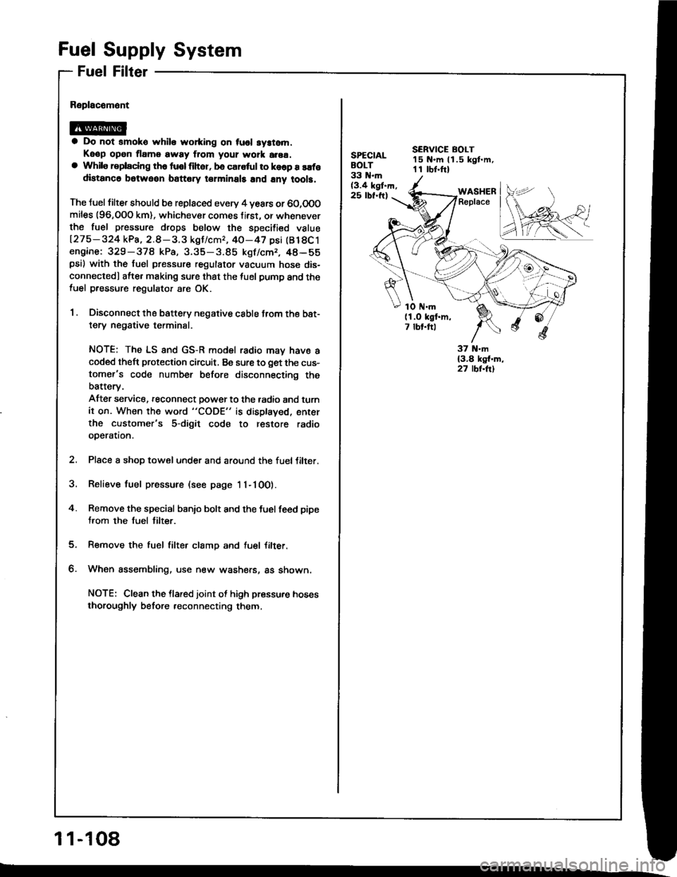
4. Remove the special banio bolt and the fuel feed pipe
from the fuel tilter.
Remove the fuel filter clamp and tuel Jilter.
When assembling, use new washers, as shown,
NOTE: Clean the llared joint ot high pressure hoses
thoroughly before reconnecting them,
1 1-108
SPECIALBOLT33 N.m(3.4 kgt.h,25 rbf.ft)
SERVICE BOLT15 N.m ll.5 kgt.m,1 I rbr.ftl
WASHERReplace
1O ttl.m(1.O kgf.m,7 tbt.ftl
Page 298 of 1413

[":::,::-'
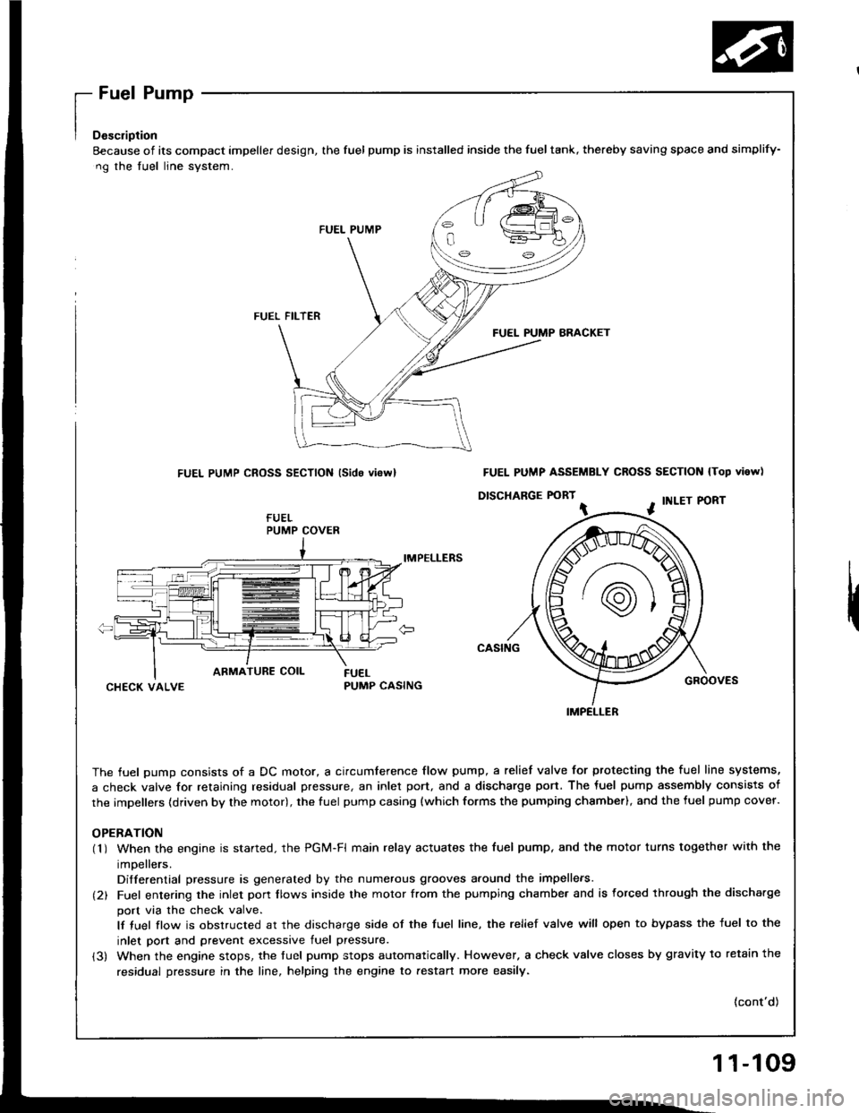
Eecause of its compact impeller design, the fuel pump is installed inside the fueltank, thereby saving space
ng the fuel line system.
FUEL PUMP
FUEL FILTER
FUEL PUMP BRACKET
FUEL PUMP CROSS SECTION lsido vi6rvl
IMPELLERS
CHECK VALVEPUMP CASING
The fuel oumo consists of a DC motor, a circumference flow pump, a relief valve for ptotecting the fuel lir
a check valve for retaining residual pressure, an inlet port, and a discharge port. The fuel pump assembly
the impellers (driven by the motor), the fuel pump casing {which forms the pumping chsmber), and the fuel p
OPERATION(1 ) When the engine is started. the PGi/t-Fl main relay actuates the fuel pump, and the motor turns togeth
impellers.
Differential pressure is generated by the numerous grooves around the impellers.
(2) Fuel entering the inlet porr flows inside the motor from the pumping chambe. and is forced through th
port via the check valve.
lf tuel flow is obstructed at the discharge side of the tuel line, the relief valve will open to bypass the
inlet port and prevent excessive fuel pressure.
(3) When the engine stops, the tuel pump stops automatically. However, a check valve closes by gravity t
residual pressure in the line, helping the engine to aestan more easily.
and simplify-
N lTop vi6w)
PORT
GROOVES
fuel line systems,
embly consists of
fuel pump cover.
together with the
rgh the discha.ge
ss the fuel to the
avitv to retain the
(cont'd)
PUMP COVER
FUEL PUMP ASSEMBLY CROSS SECTION
D|SCHARGE FORT ^ . tNLEr P
IMPELLER
11-109