check engine HONDA INTEGRA 1994 4.G Workshop Manual
[x] Cancel search | Manufacturer: HONDA, Model Year: 1994, Model line: INTEGRA, Model: HONDA INTEGRA 1994 4.GPages: 1413, PDF Size: 37.94 MB
Page 6 of 1413
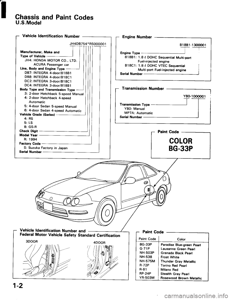
Chassis and Paint Codes
U.S.Model
Vehicle ldentification Number
Manutactulol, Make and
Typ€ of Vshicle
JH4: HONDA MOTOR CO., LTD.
ACURA Psssenger car
Line, Body and Engino Type
DB7: INTEGRA 4-door/B1 881
DB8: INTEGRA 4-door/81 8Cl
DC2: INTEGRA 3-door/B18C 1
DC4: INTEGRA 3-door/B1 8B j
Body Type and Trsnsmission Type
3: 2-door Hatchback S-speed Manual
4: 2-doot Hatchback 4-speed
Automatic
5; 4-door Sedan s-speed Manual
6: 4-door Sedan 4-speed Automatic
Vehicle Glado (Seriesl
4: RS
5: LS
8; GS-R
Check Digit
Model Yaal
R: 1994
Factory Code
S: Suzuka Factory in Japan
Serial Numb€l
Vehicle ld€ntification Number and
JH4DB754* RSOOOOO 1
I
Engine Number
8l8Br-r300@l-----T-----
Engine Typ6
81881: 1.8 f DOHC Sequentiat Muhi-pori
Fuel-injected engine
B l8Cl : 1.8 | DOHC VTEC Sequ€nrial
Multi-port Fu€l-iniected €ngin€
Se al Numbel
Paint Code
COLOR
BG.33P
Federal Motor Vehicle Safety Standard Certification
Transmission Numbsr
Y80- 1 000@ I
Transmission Type
Y80: Manual
MPTA: Automatic
Serial Numbel
Paint Code
Paint CodeColor
BG.33P
G-71P
NH-5O3P
NH-538
NH-575M
R-7 2P
R-81
RP.24P
YR.5O3M
Paradise Blue-g.€en PeErl
Lausanne Gr6en Pead
Grsnada Black Pea.l
Frost White
Thunder Grav Metallic
Torino Red Pearl
Milano Red
Stealth Gray Pearl
Rosewood Brown M€tallic
1-2
3DOOR4DOOR
Page 7 of 1413
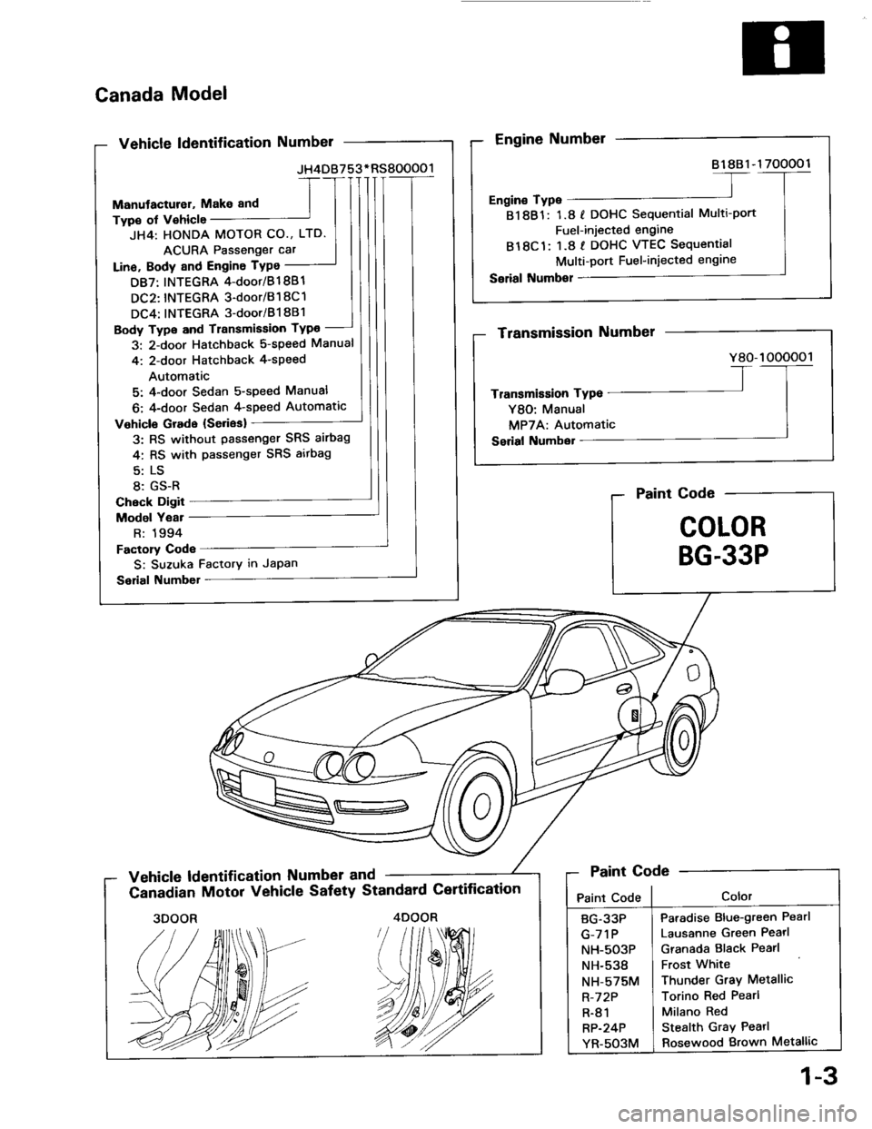
Canada Model
Vehicle ldentification Numbel
Manutacturer, Makeand
Type of v€hicle
JH4: HONDA MOTOR CO., LTD.
ACURA Passenger car
Lino. Body and Engine TYPo
D87: INTEGRA 4-doot/Bl 881
DC2: INTEGRA 3-dootBl 8C1
DC4: INTEGRA 3-doori B18B1
Body Type and Transmission TYPo
3: 2-door Hatchback 5-speed Manual
4'. 2-door Hatchback 4-speed
Automatic
5: 4-door Sedan s-speed Manual
6: 4-door Sedan 4-speed Automatic
Vehicle Grade {Sedes}
3: RS without passenger SRS airbag
4: RS with passenget SRS aitbag
8: GS-R
Check Digit
Model Yeat
R: 1994
Factory Code
S: Suzuka Factory in Japan
Serial Numbel
JH4DB753. RS800001
Engine Number
81881-1 700001
Engin€ Type
81881: 1.8 I DOHC Sequential Multi-port
Fuel-injected engine
B18C1: 1.8 I DOHC VTEC Sequential
Multi-Dort Fuel-iniected engrne
Serial Number
Paint Code
COLOR
BG.33P
Vehicle ldentification Number and
Canadian Motor Vehicle Safety Standard Certification
Transmission Number
Y80-1000001
Transmission Type
Y80: Manual
MPTA: Automatic
Serial Numbel
Paint Code
Paint CodeColor
Paradise Blue-green Pearl
Lausanne Green Pearl
Granada Elack Pearl
Frost White
Thunder Gray Metallic
Torino Red Pearl
Milano Red
Stealth Gray Pearl
Rosewood Brown Metallic
BG.33P
G-71P
NH-5O3P
NH-538
NH-575M
R-72P
R-81
RP-24P
YR-503M
3DOOR4DOOR
1-3
Page 11 of 1413
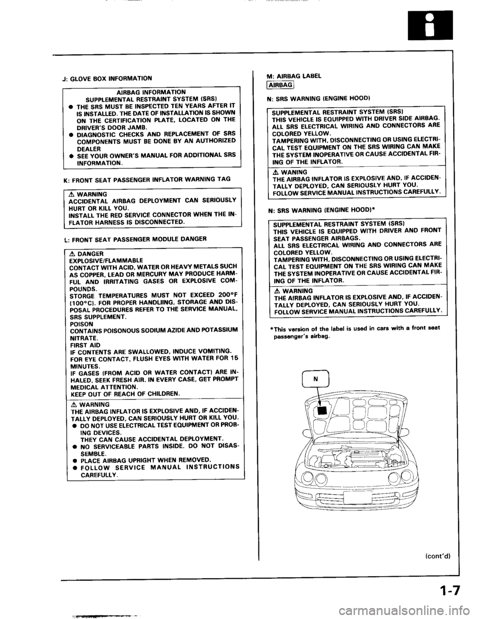
J: GLOVE BOX INFORMATIOf{
AIBBAG INFORMANO
SUPPLEMENTAL RESTiAINT SYSTEM (SRS)
. THE SRS MUST BE INSPECTED TEN YEARS AFTER IT
IS INSTALLED. TI{E DATE OF INSTALLATION IS SHOWN
ON THE CERTTFICATION PLATE, LOCATED ON THE
DRIVER'S DOOR JAMB.
. DIAGNOSTIC CHECKS AND REPLACEMENT OF SNS
COMPONENTS MUST BE DONE BY AN AUTHORIZED
DEALER
. SEE YOUR OWNER'S MANUAL FOR AODITIONAL SRS
INFORMATION.
K: FRONT SEAT PASSENGER INFLATOR WARNING TAG
A WARNING
ACCIDENTAL AIRBAG DEPLOYMENT CAN SERIOUSLY
HURT OR KILL YOU.
INSTALL THE RED SERVICE CONNECTOR WHEN THE IN-
FLATOR HARNESS IS DISCONNECTED
L: FRONT SEAT PASSENGER MODULE DANGER
A DANGER
EXPLOSIVE/FLAMMABLE
CONTACT WITH ACID, WATER OR HEAVY METALS SUCH
AS COPPER. LEAD OR MERCURY MAY PRODUCE HARM'
FUL AND IRRITATING GASES OR EXPLOSIVE COM.
POUNDS.
STORGE TEMPERATURES MUST NOT EXCEED 2OOOF
tlOO"CI. FOB PROPER HANDLIING, STORAG€ AND DIS-
POSAL PROCEDURES REF€B TO THE SERVICE MANUAL,
SBS SUPPLEMENT.
POTSON
CONTAI'\'S POISONOUS SODIUM AZIOE AND POTASSIUM
NITRATE.
FIRST AID
IF CONTENTS ARE SWALLOWED, INDUCE VOMITING.
FOR EYE CONTACT, FLUSH EYES WITH WATER FOR 15
MINUTES.
IF GASES (FROM ACID OR WATER CONTACT) ARE IN.
HALED, SEEK FRESH AIR. IN EVERY CASE. GET PROMPT
MEDICAL ATTENTION.
KEEP OUT OF REACI.I OF CHILDREN.
A' WARNING
THE AIRBAG INFLATOR IS EXPLOSIVE AND. IF ACCIDEN-
TALLY DEPLOYEO, CAN SERIOUSLY HURT OR KILL YOU.
. DO NOT USE ELECTRICAL TEST EOUIPMENT OR PROB.
ING DEVICES.
THEY CAN CAUSE ACCIOENTAL DEPLOYMENT.
. NO SERVICEAALE PABTS INSIDE. OO NOT OISAS-
SEMBLE.
. PLACE AIRBAG UPFIGHT WHEN REMOVED.
. FOLLOW SERVICE MANUAL INSTRUCTIONS
CAREFULLY.
fi{lHfiFe*% _
1-7
M: AIRBAG LABEL
AIRBAG
N: SRS WARNING IENGINE HOODI
SUPPLEMENTAL RESTRAINT SYSTEM (SBSI
THIS VEHICLE IS EOUIPPED WITH DRIVER SIDE AIRBAG.
ALL SRS ELECTRICAL WIRING AND CONNECTORS ARE
COLORED YELLOW.
TAMPERING WITH, DISCONNECTING OR USING ELECTRI-
CAL TEST EOUIPMENT ON TI{E SRS WIRING CAN MAKE
THE SYSTEM INOPERATIVE OB CAUSE ACCIOENTAL FIR'
ING OF THE INFLATOR.
A. WANING
THE AIRBAG INFLATOR IS EXPLOSIVE AND, IF ACCIDEN-
TALLY DEPLOYED, CAf{ SERIOUSLY HURT YOU'
FOLLOW SERVICE MANUAL INSTRUCTIONS CAREFULLY.
SUPPLEMENTAL RESTRAINT SYSTEM {SRSI
THIS VEI{ICLE IS EOUIPPED WITH DRIVER ANO FRONT
SEAT PASSENGER AIRBAGS.
ALL SRS ELECTRICAL WIRING AND CONNECTORS ARE
COLORED YELLOW.
TAMPENING WITI{, DISCONNECTING OR USI G ELECTRI'
CAL TEST EOUIPMENT ON THE SRS WIRING CAN MAKE
THE SYSTEM INOPERATIVE OR CAUSE ACCIDENTAL FIB'
ING OF THE INFLATOB.
A WABNING
THE AIRBAG INFLATOR IS EXPLOSIVE AI{O, IF ACCIDEN-
TALI-Y DEPLOYED, CAN SEBIOUSLY HURT YOU'
FOLLOW SERVTCE MANUAL INSTRUCTIONS CAREFULLY.
N: SRS WARNING IENGINE HOODIi
'This vorsion
passonger's
ol tho labol is u36d in cs.t with a front soat
airbag.
{cont'd)
Page 26 of 1413
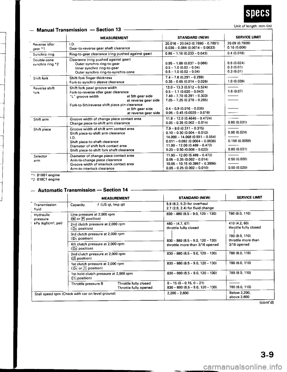
MEASUREMENISTANDARD INEW)SERVICE LIMIT
Reverse idlergear'1LD.Gear-to-reverse gear shaft clearance20.016 - 20.043 (0.7880 - 0.7891)0.036 - 0.084 (0.0014 - 0.0033)20.09 (0.7909)
0.16 (0.006)
Synchro ringRing-to-gear clearance (ring pushed against 99ar)0.85 - 1.10 (0.033 - 0.043)0.4 (0.0't6)
Oouble conesynchro ring *2Clearance {rin9 pushed against gear)
Outer synchro ring-to-gearlnner synchro ring-to-gearOuter synchro ring-to-synchro cone
0.95 r 1.68 (0.037 - 0.066)0.5 - 1.0 (0.02 - 0.04)0.5- 1.0 {0.02 -0.04)
0.6 (0.024)
0.3 (0.01)
0.3 (0.01)
Sh itt forkShift tork finger thicknessFork-to synchro sleeve clearance7.4,7.6 (0.291 - 0.299)0.35 - 0.65 (0.014 - 0.026)1.0 (0.039)
qeverse shiftShift fork pawl groove widthFork-to-reverse idler gear clearance"1" groove width at sth gear sideat reverse gear side
Fork-to-5th/reverse shift piece pin clearanceat 5th gear sideat reverse gear side
13.0 - 13.3 (0.512 - 0.524)0.5 - 1.1 10.020 - 0.043)7.40 - 7.70 (0.291 -0.303)
7.05 - 7.25 (0.278 - 0.28s)
0.4 - 0.9 {0.016 - 0.03s)0.05 - 0.45 (0.0020 - 0.018)
13907)
Shift armGroove width of change piece contact area
Change piece-to-shift arm clearance11.8 - 12.0 (0.4646- 0.4724)0.05 - 0.35 (0.002 - 0.014)0.8010.031)
Shift pieceGroove width of shift arm contact area
Shift piece'to-shift arm clearanceLD.Shift piece-to-shaft clearanceDiameter of shift Iork cont6ct areaShift piece-to-shift fork shaft clearance
7.9 - 8.0 (0.311 -0.315)
0.10 - 0.30 (0.004 - 0.012)14.000 - 14.068 {0.551 - 0.554)0.011-0.092 (0.0004 - 0.0036,1'1.90 - 12.00 (0.469 - 0.472)0.20 - 0.50 (0.008 - 0.020i
0.60 (0.024)
0.150 (0.0059)
oso to.oart
SelectorDiameter of change piece contact areaArm-to-change piece clearanceGroove widlh of interlock contact area
Arm-to-interlock clearance
11.90 - '�t2.00 (0.469 - 0.472)0.05 - 0.35 {0.002 - 0.014)10.05 - 10.15 {0.3957 - 0.3996}0.05 - 0.2s (0.002 - 0.010)
0.50 (0.020)
0.50 (0.020)
Manual TransmissionSection 13
'1:81881 engine'2 818C1 engine
- Automatic TransmissionSection 14
Unit of length: mm (in)
(cont'd)
- oEutrlrrl rr
MEASUREMENTSTANDARD {NEWISERVICE LIMIT
TransmissionlluidCapacity I (US qt, lmp qt)5.9 16.2, 5.2)for overhaul2.7 (2.9, 2.4) for lluid change
Hydraulicpressure
I kPa lkgflcm'�, psi)
Line pressure at 2,000 rpm(E or E position)830 - 880 (8.5 - 9.0, 120 - 130)780 {8.0, 110)
2nd clutch pressure at 2,000 rpm(DJ position)460 - 14.7, 67)throttle Iully closed
II830 - 880 (8.5 - 9.0, 120 - 130)
throttle more than 3/16 opened
410 {4.2.60)throttle fully closed
I780 {8.0, 110)throttle more than3/16 opened
3rd clutch pressure at 2,000 rpm(lqr posirion)
4th clutch pressure at 2,000 rPm
{E position)
2nd clutch pressure at 2,000 rPm(Elposition)830 - 880 {8.s - 9.0. 120 130)780 (8.0, 110)
1st clutch pressure at 2,000 rpm([O or E position)830 - 880 (8.5 - 9.0, 120 - 130)780 (8.0, 110)
'lst'hold clutch pressure at 2,000 rpm(Elposition)830 - 880 {8.5 - 9.0, 120 - 130}780 (8.0, 110)
Throttle pressure B Throttle fully closedThrotlle Iully opened0 - 1s {0-0.15,0- 21)830 - 880 (8.5 - 9.0, 120 - 130)780 18.0, 110)
Stall speed rpm (Check with car on level ground)2,200 - 2,600Below 2,200,above 2,600
3-9
Page 56 of 1413
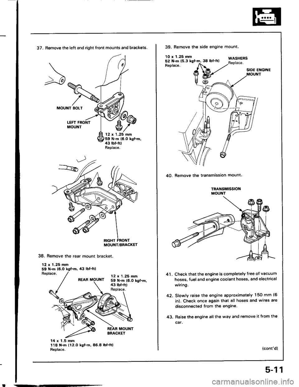
37, Remove the left and right front mounts and brackets.
MOUNT BOLT
LEFT FRONTMOUNT
12 t 1.25 nn59 N.m {6.0 kgt.m,43 lbf.trlReplace.
38. Remove the rear mount bracket,
12 r 1.25 mm59 N.m (6.0
Replace.43 rbf.ftl
REAR MOUNT12 r 1.25 m|n59 N.m {6.0 kgt.m,43 tbt.frlReplace.
14 x 1.5 mm118 t{.m (12.O kgt.m,86.8 lbl.ft}R6place.
MOUNT/BRACKET
39. Remove the side engine
10 r 1.25 mm
mounr.
WASHERSReplace.Replace.SIDE ENGIITE
40. Remove the transmission mount
TRA SM|SS|OI{MOUNT
41. Check that the engine is completely free of vacuum
hoses, fuel and engine coolant hoses, and electrical
wi.ing.
42. Slowly raise the engine approximately 150 mm (6
in), Check once again that all hoses and wires are
disconnected from the engine
43. Raise the engine all the w8y and remove it trom the
car.
(cont'dl
5-11
Page 90 of 1413
t
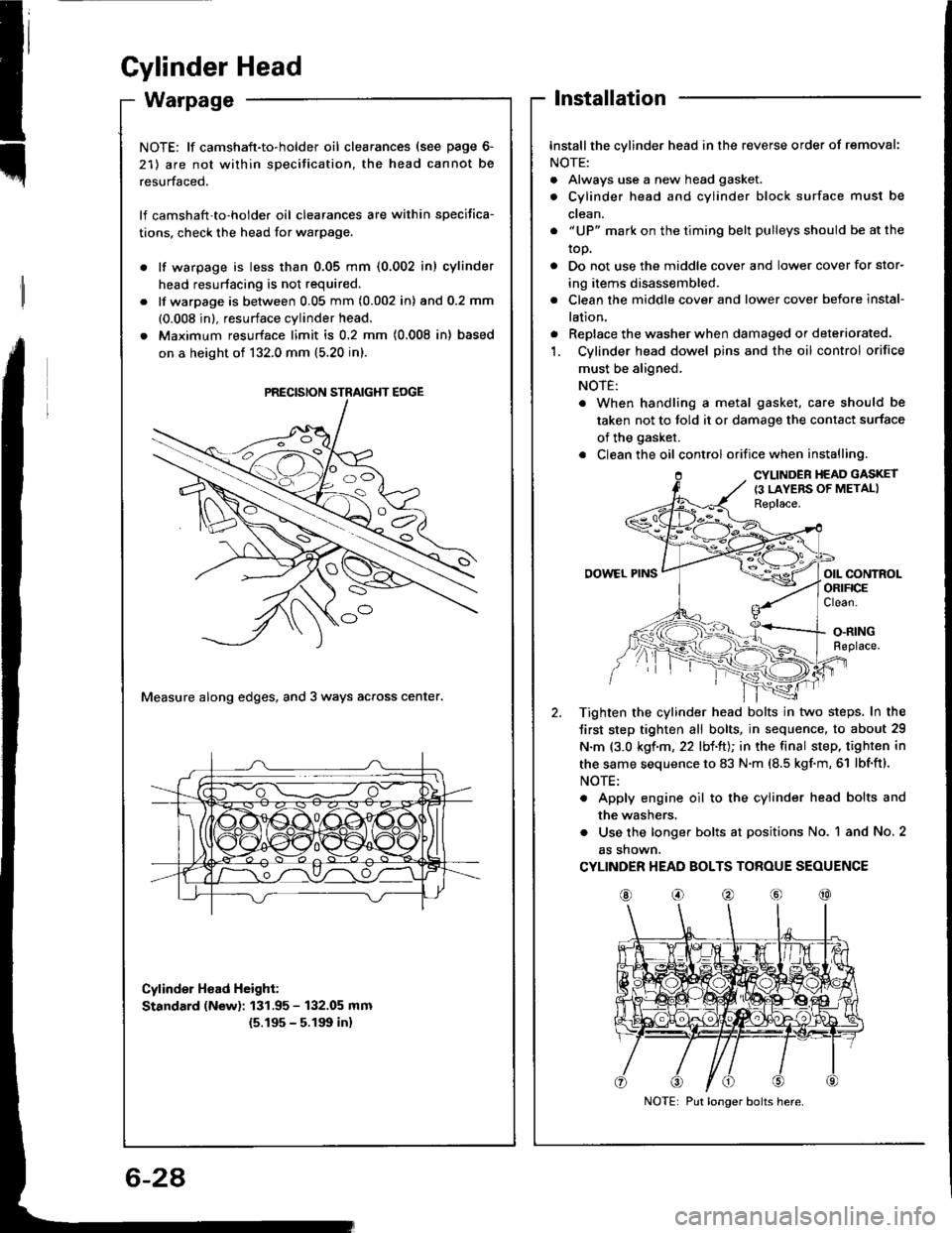
Gylinder Head
Installation
Installthe cylinder head in the reverse order of removal:
NOTE:
. Always use a new head gasket.
. Cylinder head and cylinder block surface must be
ctean.
. "UP" mark on the timing belt pulleys should be at the
top.
. Do not use the middle cover and lower cover for stor-
ing items disassembled.
. Clean the middle cover and lower cover before instal-
lation.
. Replace the washer when damaged or deteriorated.'1. Cylinder head dowel pins and the oil control orifice
must be aligned,
NOTE:
. When handling a metal gasket, care should be
taken not to told it or damage the contact surface
of the gasket.
. Clean the oil control orifice when installing.
CYLINDER HEAD GASKET
{3 LAYERS OF METALIReplace.
OOWEL PINSorl coNtnolORIFICEClean.
O.RINGReplace.
Tighten the cylinder head bolts in two steps. In the
Jirst step tighten all bolts, in sequence, to about 29
N.m {3.0 kgf.m, 22 lbl.ltJ; in the final step, tighten in
the same sequence to 83 N.m (8.5 kgf.m, 61 lbf'ft).
NOTE:
. Apply engine oil to the cylinder head bolts and
the washers.
. Use the longer bolts at positions No. 1 and No. 2
as shown.
CYLINDER HEAD BOLTS TOROUE SEOUENCE
@o@@@
NOTE: lf camshaft-to-holder oil clearances (see page 6-
21) are not within specitication, the head cannot be
resurfaced.
lf camshaft'to-holder oil clearances are within specifica-
tions, check the head for warpage.
lf warpage is less than 0.05 mm (0.002 in) cylinder
head resurtacing is not required.
lf warpage is between 0.05 mm (0.002 in) and 0.2 mm
(0.008 in), resurface cylinder head.
Maximum resurface limit is 0.2 mm (0.008 in) based
on a height of 132.0 mm (5.20 in).
Measure along edges, and 3 ways across center.
Cylinder Hoad Height:
Standard (New): 131.95 - 132.05 mm
{5.195 - 5.191t in}
PRECISION STRAIGHT EOGE
Put longer bolts here.
Page 93 of 1413
14.
16.
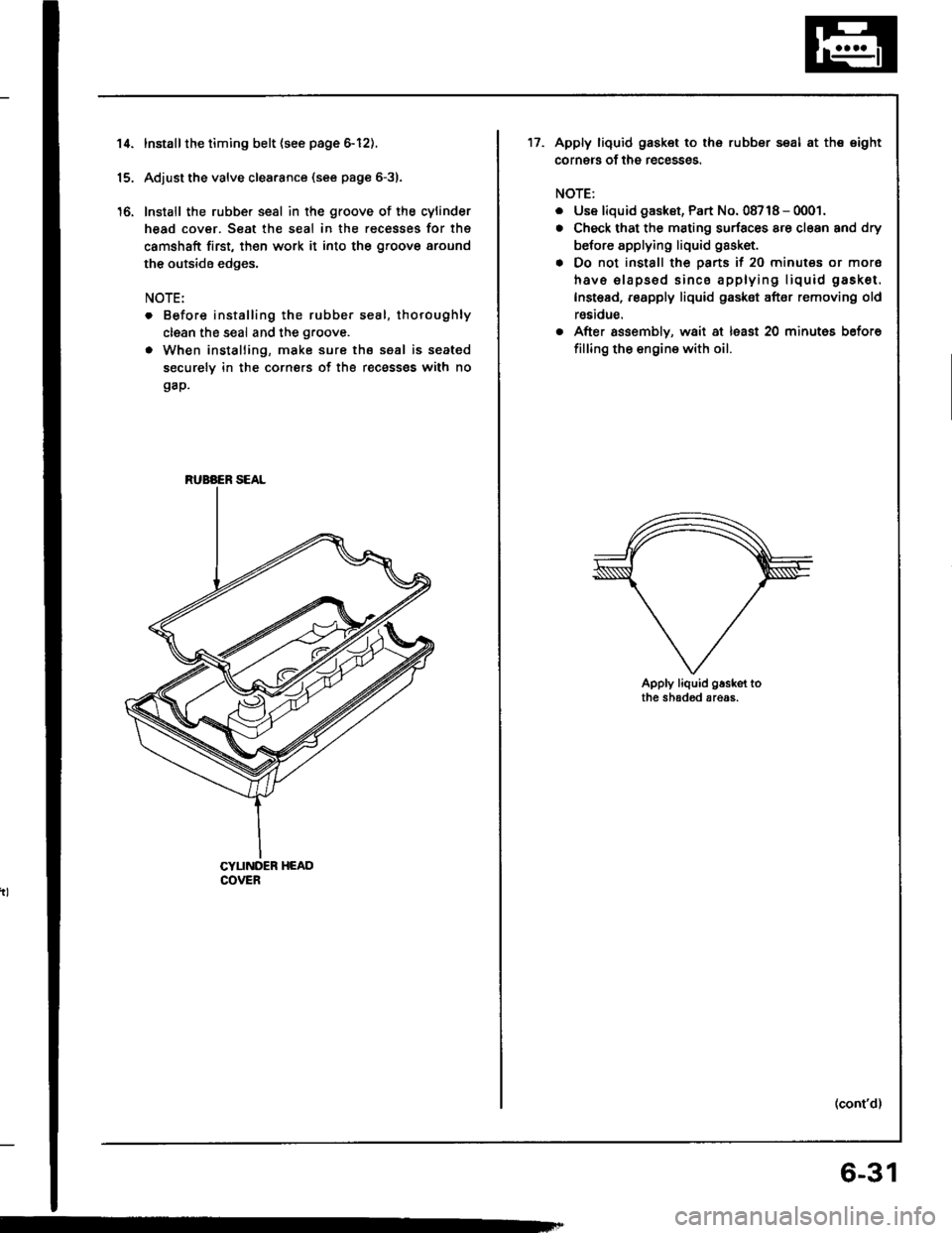
Installthe timing belt {see page 6-12).
Adjust the valve clea.ance (see page 6-31.
Install the rubber seal in the groove of the cylinder
head cover. Seat the seal in the recesses for thg
camshaft first, th€n work it into the groove around
the outside edges,
NOTE:
. Before installing the rubber seal, thoroughly
clean the seal and the groove.
. When installing, make sure the seal is seated
securely in the corners of the recass€s with no
gap.
CYUNDER HEADCOVER
RUBAER SEAL
17.Apply liquid gask€t to the rubber seal at the eight
corners of the recesses.
NOTE:
. Use liquid gaskst, Part No. 08718 - 0001.
. Check that the mating surfaces are cl€an and dry
before applying liquid gasket.
. Do not install the parts if 20 minutes or mor6
havs elapsod sinco applying liquid gasket.
Instead, reapply liquid gasket after removing old
reaidue.
. After assembly, wait at lsast 20 minutes before
filling the engine with oil.
Apply liquid g.sket tothe shaded areas.
(cont'd)
6-31
Page 99 of 1413
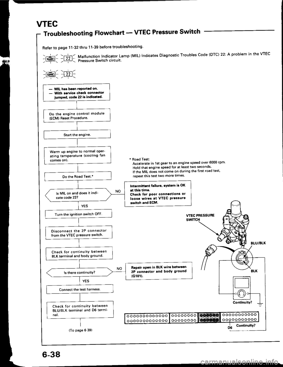
wEc
6-38
Troubleshooting Flowchart - VTEC Pressure Switch
Refer to page 11-32thru 11-39 beJore troubleshooting'
-.+- -r";-r- Malfunction Indicator Lamp (MlL) indicates Oiagnostic Troubles Code (DTC) 22: A problem in the VTEC- l{{?l- ;l ziz r: pressur€ Switch circuit.
-lr@l- |22 1-
* Road Test:Accolerato in lst gear to an engine speed over 6000 rpm
Hold that engine speed for at least two seconos'
lf the MIL does not come on during the first road test'
reoeat this test two more limes.
- MIL har bagn.oportcd on.- With t.rvic. chack connactor
iump.d, cod€ 22 it indic.t.d.
Do the engine control module(ECM)Reset Procedure.
Warm !p engine to normal oper-
ating temperstur€ (cooling fan
comes on).
Do the Boad T€st.'
Intc.mift.nt failu.o, ry3tom ia OK
at thi. tim..Chack for pool connaction3 ol
loo!. rvirat at VTEC Ptasturo3whch and ECM.
ls MIL on and does it indi'
cate code 22?
Turn lhe ignition switch OFF
Disconnect the 2P connector
lrom the VTEC Pressure switch.
Check Ior continuity between
BLK terminal and body ground.
Rcpair opcn in BLK wit. botwcon
2P connector rnd body ground
tG101l.
Check for continuity between
8LU/8LK terminal and D6 termi'
nal.
(To page 6 39)
Page 100 of 1413
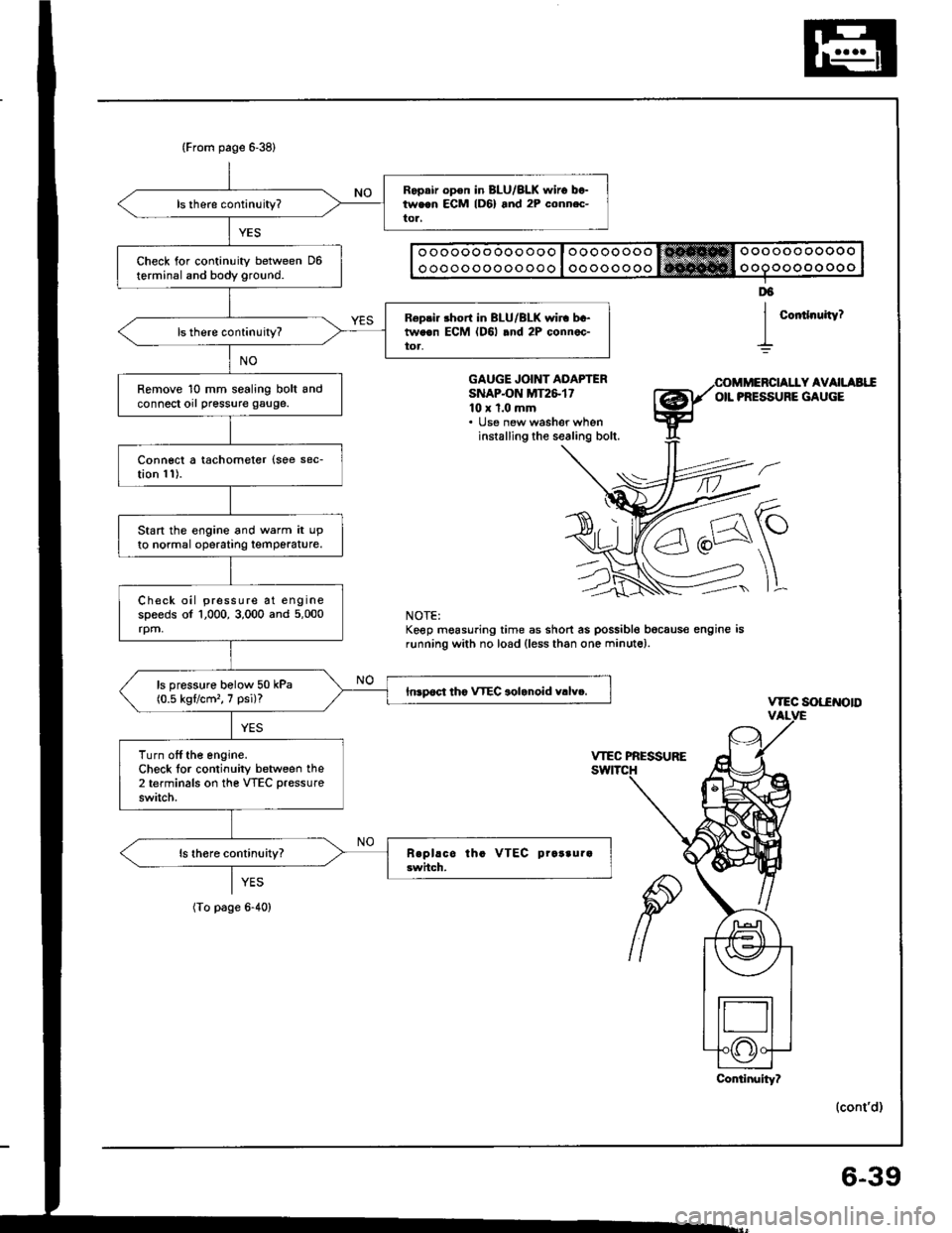
(From page 6-38)
Ropair op€n in BLU/BLK $,iro between ECM lD6) and 2P conn.c-tor,
Check for continuity between D6terminal and body ground.
R6pri. short in BLU/BLK wir. bc-tweon ECM (D6l .nd 2P connec-toa,
Remove 10 mm sealing bolt andconnect orl pressure gauge.
Connect a tachometer {soe sec-tion 11).
Start the engine and warm it upto normal operatrng temperature.
Check oil pressure at enginespeeds of 1,000, 3,000 and 5,000rpm,
ls pressure bolow 50 kPa(0.5 kgflcm'�, 7 psi)?Inrpoct tho VTEC aolanoid v.lv..
Turn off the engine.Check lor continuity between the2 terminals on the VTEC pressure
switch.
o oooooo ooo ooo I oooooooo trt!*Hffi Oooooo ooooo
o oooo ooooo ooo I oo oooo ooo ooooo oo oo o
Coitlnuity?
D6
I
GAUGE JOINT ADAPTERSNAPON MT2&1710 x 1.0 mm. lJse new washer wheninstalling the sealing bolt.
Y AVAILAEIIOIL PRESSURE GAUGE
\-
]L
vtEc sot-€NotD
(cont'd)
NOTE:Keep mgasuring time as short as possible bocaus€ engine isrunning with no load (less than one minute).
YES
(To page 6-40)
Conlinuity?
6-39
Page 101 of 1413
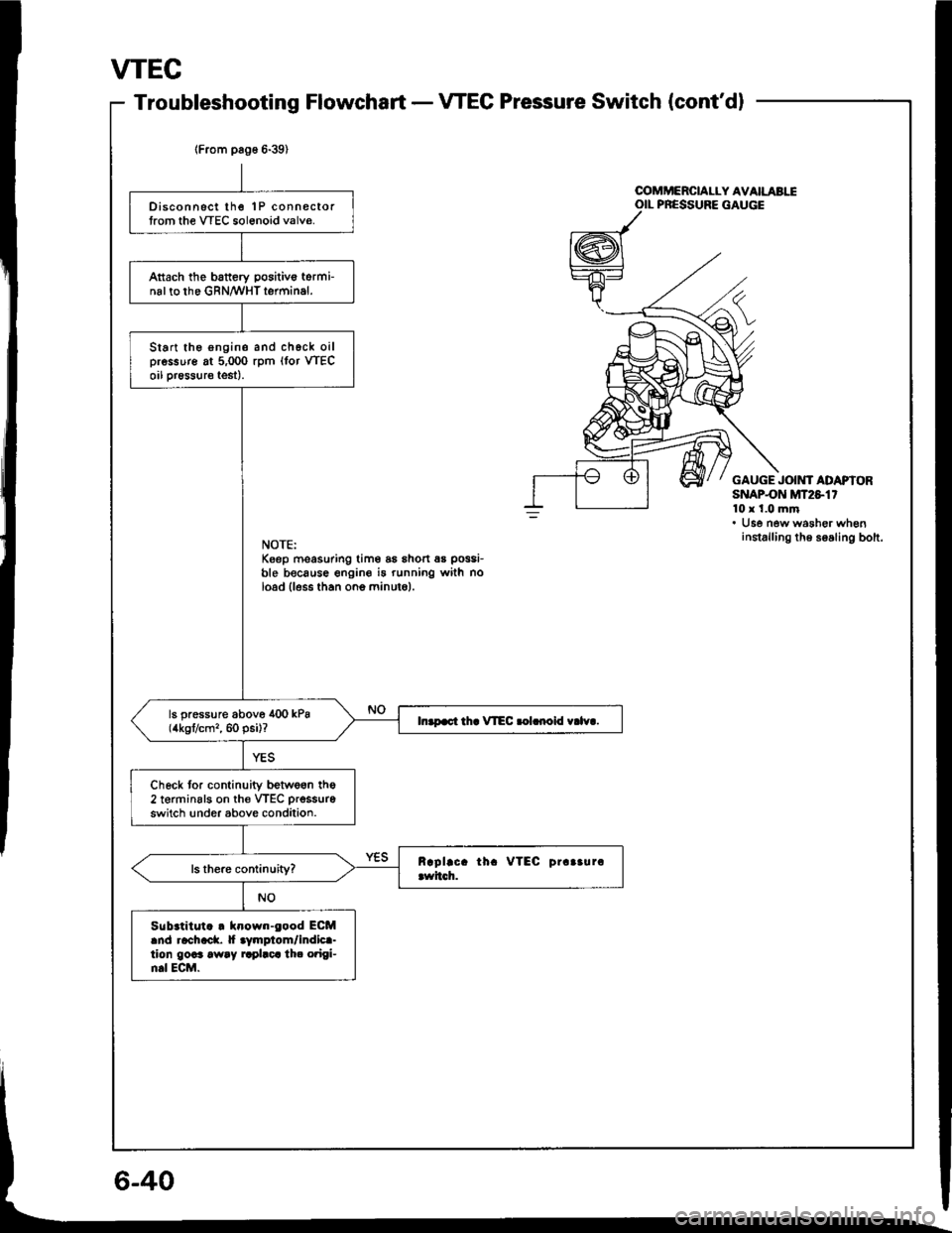
VTEC
Troubleshooting FlowchartVTEC Pressure Switch (cont'dl
lFrom pag6 6-39)
Disconnsct lhe 1P connectortrom the VTEC sol6noid valve.
Attach the battery positivo torminal to the GRN/WHT terminal.
Start the engine and chgck oilpressure at 5,000 rpm (lor VTECoil pr€ssure test).
ls pressure above 400 kPa(4kgt/cm,, 60 psi)?In.p.ct th. VIEC .olrnoid v.lv..
Check tor continuity betwe6n the2 terminsls on th€ VTEC prsssure
switch !nder above condition.
Sub.titut. . klown-eood ECMand rachack. |f aymplom/indica-tion goaa away rrplaca th. o?igi-n.l ECM.
u
OOMMERCIALLY AVAILABIIOIL PRESSURE GAUGE
GAUGE JOIMf ADAPIORSNAPON MT2S1'10x 1.0 mm. Use new washer wheninstalling th6 soaling bolt.NOTE:Keep moasuring tim6 as shon 6s possi-
ble because engine i5 running with noload lless than ono minuto).