Vacuum HONDA INTEGRA 1994 4.G User Guide
[x] Cancel search | Manufacturer: HONDA, Model Year: 1994, Model line: INTEGRA, Model: HONDA INTEGRA 1994 4.GPages: 1413, PDF Size: 37.94 MB
Page 203 of 1413
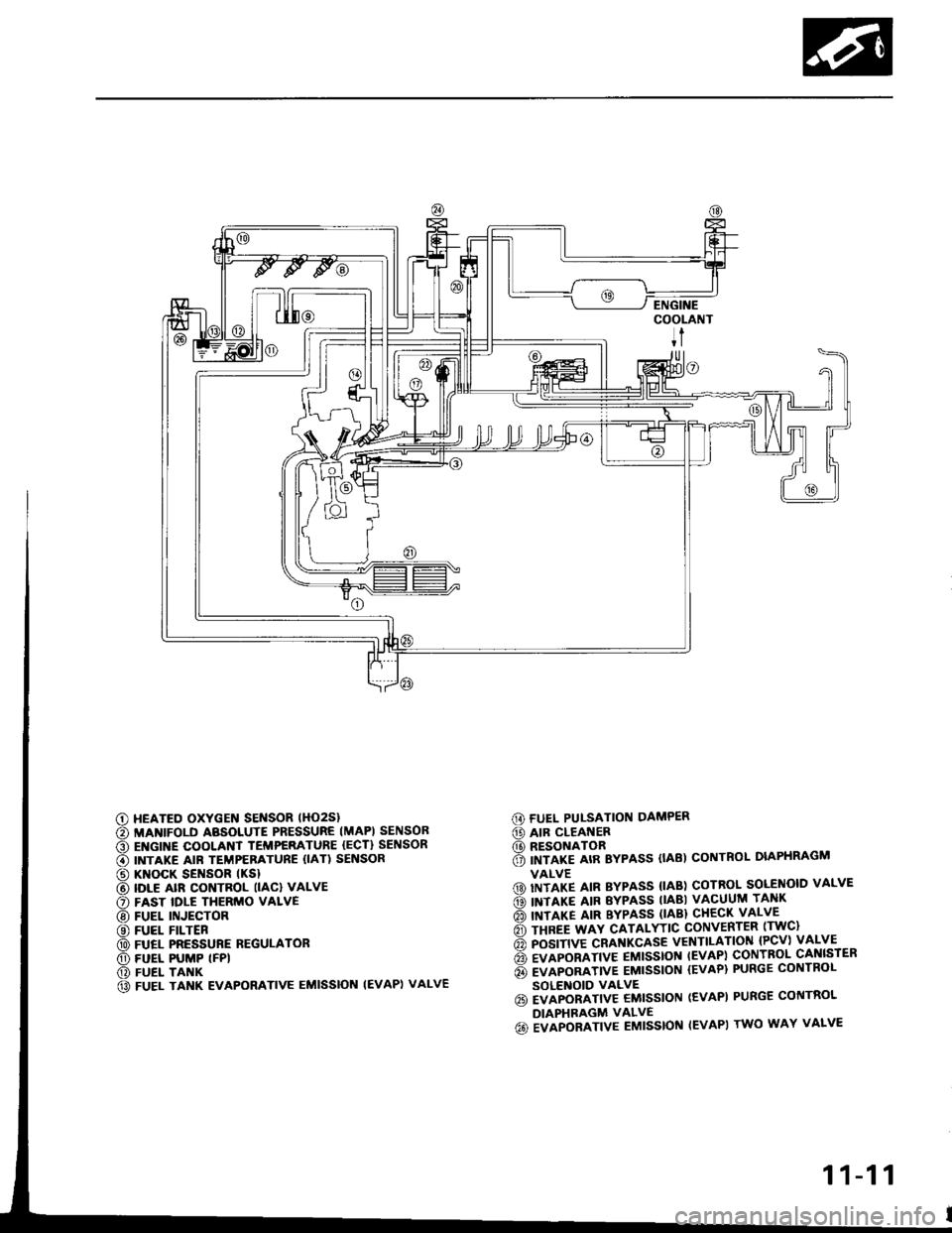
G) FUEL PUI-SATION DAMPER
@ AIR CLEANER(D RESONATOR6 imrlre arR Bypass (tAB) coNTRoL DIAPHRAGM
VALVE(D) IITITP IIN BYPASS {IAB) COTROL SOLENOID VALVE
ds) INTIXT AIR EYPASS TIABI VACUUM TANK
rio'l rnrarg ltn BYPASS (lABl cHEcK vALvE
6 rsnee wav cATALYTtc coNvERTER lrwc)
6 posrnve cRAf{KcAsE vENTILATIoN {Pcv) vALVE
6 evlponlrtve EMtsstot{ tEvAPl coNTBoL cANlsrER
6 evlponltvE EMtssloN {EvAP} PURGE coNTRoL
SOLENOID VALVE6i EVAPORATIV€ EMISSION (EVAPI PURGE CONTROL
DIAPHRAGM VALVE
6o ivlpoalrtve Eutsstof{ IEVAPI rwo wAY vALvE
c) HEATED OXYGEN SENSOR lHO2Sl
€) MANIFOLD ABSOLUTE PRESSURE IMAPI SENSOB
O EI{GINE COOLANT TEMPERATURE {ECT} SENSOR
€) INTAKE AIR TEMPERATURE {IAT) SENSOR
@ KNOCK SENSOR tKSl
@ IDLE alR coNTRoL llAcl vALvE
O FAST IDLE THERMO VALVE
@ FUEL INJECTOR
@ FUEL FILTER
@ FUEL PRESSURE REGULATOR
O) FUEL PUMP (FPI
@) FUEL TANK
@ FUEL TANK EVAPORATIVE EMISSION IEVAPI VALVE
11-11
Page 233 of 1413
3. Fuel Cut-oft Control
a During deceleration with the throttle valve closed, current to the {uel injectors is cut otJ to improve fuel economy
at speeds over tollowing rpm:
. 8188l engine: 91O tpm (Canada model: 1,O50 rpm)
. 818C1 engine: 95O tpm (Canada model: l,O5O rpm)
a Fuel cut-olf action also takes place when engine speed exceeds, 7,O0O rpm {81 8B1 engine), 8,1O0 rpm (B 18Cl
engine), regardless oI the position of the throttle valve, to protect the engine from ovet-revving.
A/C Compressor Clutch Relay
When the ECM receives a domand for cooling trom the air conditioning system, it del8ys the compressor from being
enetgized, and enriches the mixture to assure smooth transition to the A/C mode.
Evaporative Emission (EVAP) Purge Control Solenoid Valve
When the engine coolant tempersture is below 163oF {73"C), the ECM supplies a ground to the EVAP pu.ge control
solenoid valve which cuts vacuum to the EVAP purge control diaphragm valve.
Intake Air Bypsss (lAB) Control Sol€noid Valve
When the engine rpm is below 5,750 rpm, the IAB control solenoid valve is activated by a signal from the ECM,
intske air flows through the long intake path, then high torque is delivered. At spaeds highe. than 5,750 rpm, the
solenoid valve is deactivated by the ECM, and intake air flows through the short intake path in order to reduce the
resistance in airflow.
ECM fail-safe/bEck-up Functions
1. Fail-sate Function
When an abnormality occurs in a signal from a sensor, the ECM ignores that signal and assumes a pre-progtammed
value tor that sensor that allows the engine to continue to run.
Back-uD Function
When an abnormalitv occurs in the ECM itself, the fuel iniectors are controlled by a back-up citcuit independent of
the system in order to permit minimal driving.
Self-diagnosis Function IMaltunction Indicator Lamp {MlL)1
Wh6n an abnormality occurs in a signal from a sensor, the ECM supplies ground for the MIL and stores the code
in erasable memory. When the ignition is initially turned on, the ECM supplies ground tor the MIL tor two seconds
to check the MIL bulb condition.
Two Trio Detection Method
To prevent tals€ indications, th€ Two Trip Dstection Method is used for the HO2S and fuel metering-related self-
diagnostic tunctions. When an abnormslity occurs, the ECM stores it in its memo.y. Wh€n the ssme sbnormality
recurs alter the ignition switch is turned OFF and ON ag8in, the ECM informs the driver by lighting the MlL.
However, to ease troubleshooting, this function is canc€ll€d when you short the service check connector. The MIL
will then blink immedistelv when an abnormality occurs.
4.
6.
2
4.
11-41
Page 290 of 1413
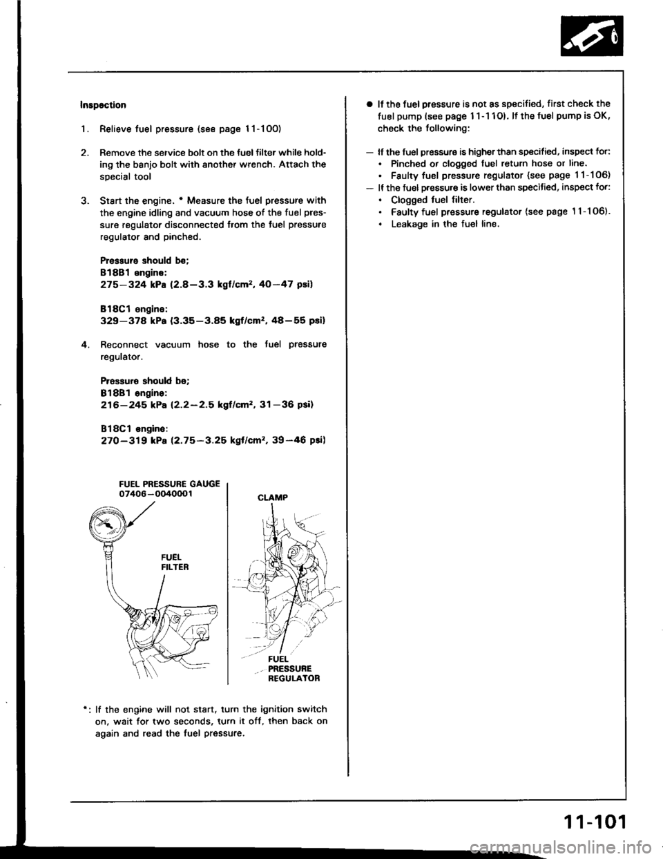
Insp6ction
1. Relieve fuel pressure (see page 11-1OO)
2. Remove the service bolt on the tueltilter while hold-
ing the banjo bolt with another wrench. Attach the
special tool
3. Siart the engine. * Measure the {uel pressur€ with
the engine idling and vacuum hose of the fuel pres-
sure regulator disconnected from the tuel pressure
regulator and pinched.
Pressure should b€;
818B1 engins:
275-324 kPa (2.8-3.3 kgl/cm2, 40-47 psil
818C1 ongine:
329-37a kPa (3.35-3.85 kgf/cmz, 48-55 pei)
4. Reconnect vacuum hose to the tuel plessure
regulator.
Prossuro should b€;
Bl8Bl ongino:
216-245 kPa (2.2-2.5 kgf/cm'�, 31 -36 psil
B18Cl on9in6:
27O-319 kPa 12.75-3.25 kgt/cm'�, 39-46 psi)
FUEL PRESSURE GAUGE07406 - OO4000 1
lf the engine will not stan, turn the ignition switch
on. wait for two seconds, turn it off, then back on
again and read the fuel pressure.
CLAMP
a lf the fuel pressure is not as specified, first check the
fuel pump (see page 1 l - 1 1O). lf the fuel pump is oK,
check the following:
- lf the fuel pressuro is higherthan specified, inspect for:
. Pinched or clogged tuel return hose or line.
. Faulty fuel pressure regulator (see page 11-106)
- It the fuel p.essu.e is lower than specitied, inspect fo.:
. Clogged fuel tilter.. Faulty fuel pressure regulator (see page '11-106).
. Leakage in the fuel line.
1 1-101
Page 294 of 1413
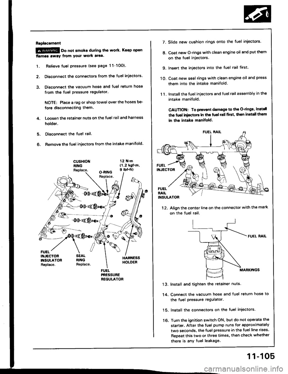
Rapl!c!ment
@ oo not smoko during tho work. Keep open
fllma3 lway from your wolk aloa.
1. Retieve tuel pressure {see page 1 1-10O).
2. Disconnect the connectors trom the fuel iniectors.
3. Disconnect the vacuum hose and fuel return hosa
from the fuel pressure regulatol.
NOTE: Place a r8g or shop towel over the hoses be-
for6 disconnecting them.
4. Loosen the retainer nuts on the Juel rail and harness
holder.
Disconnect the tuel 18il.
Remove the fuel injectors from the intake manifold.
5.
6.
cusHloNRINGReplace.
FUEL
7.
t'.
9.
10.
13.
14.
16.
11.
Slide new cushion rings onto the luel iniectors.
Coat new O-rings with clean engine oil and put them
on the fuel injectors.
Insen the injectors into the tuel rail tirst.
Coat new seal rings with clean engine oil and press
them into the intake manifold.
Install the Juel iniectors and fuel rail assembly in the
intake manilold.
CAUTION: To plovont damage to th€ O-dngs, instsll
tho fuol inioctors in tho fuol r8il first, thon install th€m
in the intaks mEnitold.
12. Align the center line on the connector with the mark
on the fuel rail.
FUEI. RAIL
MABKI'{GS
Install and tighten the retainer nuts
Conn€ct the vacuum hose and tuel retuln hose to
the fuel pressure regulator.
lnstall the connecto.s on the fuel injectors.
Turn the ignition switch ON, but do not operate the
starte.. After the tuel pump runs for approximately
two seconds, the tuel pressure in the fuelline rises.
ReDeat this two or three times, then check whether
there is any fuel leakage
11-105
Page 295 of 1413
Fuel Supply System
Fuel Pressure Regulator
FUELRETURI{
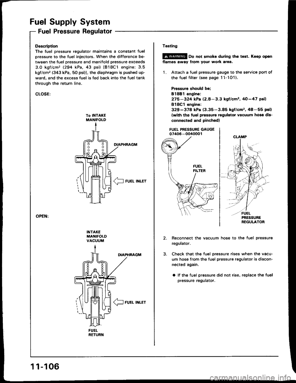
Description
The fuel pressure .egulator maintains a constant Juel
pressure to the tuel injectors. When the difference be-
tween the fuel pressure and manitold pressur€ exceeds
3.O kgf/cm'� 1294 kPa, 43 psi) tB18C1 engine: 3.5
kgt/cm, (343 kPa, 50 psi)], the diaphragm is pushed up-
ward, and the excess fuel is fed back into the fuel tank
through the retufn line,
CLOSE:
DIAPHRAGM
__l FUEL INLET
INTAKEMA'{IFOLDVACUUM
DIAPHNAGM
/1-
\J FUEL INLET
11-106
Te6ting
@ oo not smoko during the t€st. Ko6p opon
flames away from your work area,
1. Attach a fuel pressure gauge to the se.vice port of
the luel filter {see page 11-101).
Prossuro should be;
Bl88l ongin€:
275-324 kPa (2.8-3.3 kgf/cm', 40-47 psil
B18Cl €ngino:
329-378 kPa (3.35-3.85 kgf/cm'�.48-55 pEi)
(with tho tuol pressure rsgulator vacuum hoso dls-
connoctod and pinched)
FUEL PRESSURE GAUGE07406 - oO/IOOO 1
Reconnect the vacuum hose to the fuel pressure
regulator.
Check that the tuel pressure rises when the vacu-
um hose from the fuel pressure regulator is discon-
nected again.
a lf the fuel pressure did not rise, replace the fuel
pressure regulatot.
Page 296 of 1413
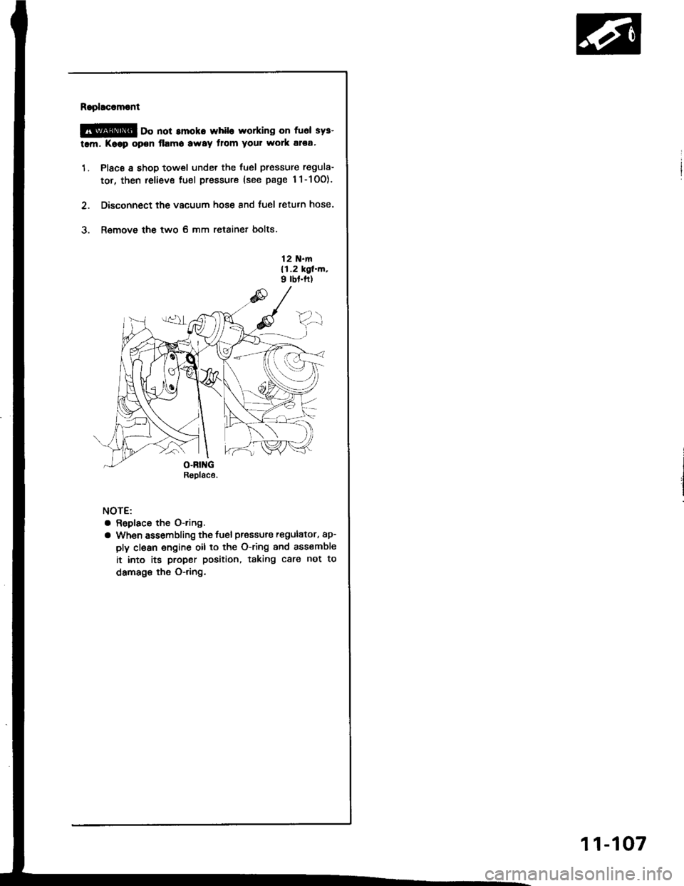
Raplacoment
@ oo not amoko whil6 working on fuel sys-
tam. Koop open flamo away tlom your work atea'
1. Place a shop towel under the fuel pressure regula-
tor, then reliev€ tuel pressure (see page 1l-10O).
2. Disconnect the vacuum hose and fuel return hose.
3. Remove the two 6 mm retainer bolts.
12 N.m{1.2 kgl.m,9 rbf.ft)
NOTE:
a Replaco the O-ring.
a When assembling the fuel pressure regulator, ap-
ply clean engine oil to the O-ring and assemble
it into its proper position, taking care not to
damage the O-dng.
Rsplace.
11-107
Page 297 of 1413
Filter
Fuel Supply System
Fuel
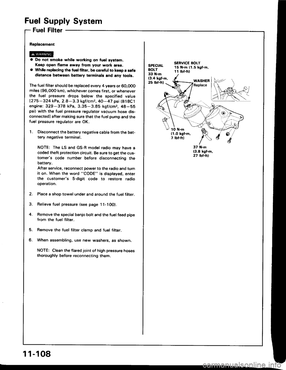
a Do not smoko while wo*ing on tusl system.
Keop open tlame away ftom your wotk area.a While replaclng th6 tusl liher, be caletul to koop a safodistanc6 betweon battery torminals and any tool3.
The Juel filter should b€ replaced every 4 years or 60,0O0miles (96,OOO km), whichever comes f irst. or wheneverthe fuel pressure drops below the specilied value
127 5 - 324 kPa, 2.8 - 3. 3 kgJ/cmr, 40-47 psi (Bl 8C 1engine: 329-378 kPa, 3.35-3.85 kgf/cmr, 48-55psi) with the fuel pressure regulator vacuum hose dis-
connectedl afte. making sure that the tuel pump and thefuel pressure regulator are OK.
1 , Disconnect the battery negative cable trom the bat-
tery negative terminal.
NOTE; The LS and GS-R model radio may have acoded theft protection circuit, Be sure to get the cus-
tomer's code number before disconnecting the
batterv.
After service, reconnect power to the tadio and turn
it on. When the word "CODE" is displaved, enter
the customer's 5-digit code to restore radio
operation.
2. Place a shop towel under and around the fueltilter.
3. Relieve fuel pressure (see page 11-100).
4. Remove the special banio bolt and the fuel feed pipe
from the fuel tilter.
Remove the fuel filter clamp and tuel Jilter.
When assembling, use new washers, as shown,
NOTE: Clean the llared joint ot high pressure hoses
thoroughly before reconnecting them,
1 1-108
SPECIALBOLT33 N.m(3.4 kgt.h,25 rbf.ft)
SERVICE BOLT15 N.m ll.5 kgt.m,1 I rbr.ftl
WASHERReplace
1O ttl.m(1.O kgf.m,7 tbt.ftl
Page 309 of 1413
lntake Air System
Throttle Body
Description
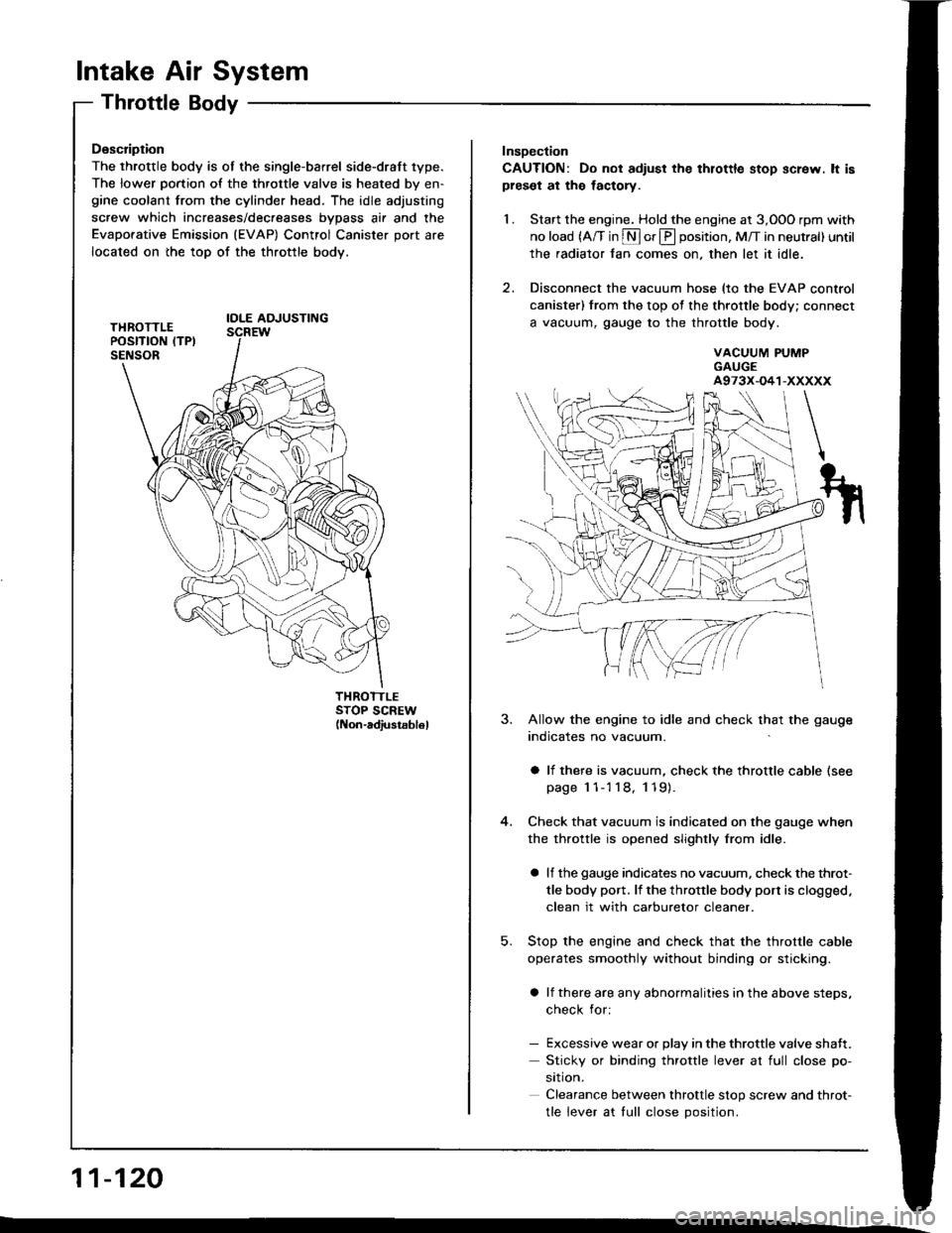
The throttle body is ot the single-barrel side-draft 1ype.
The lower portion of the throttle valve is heated by en-gine coolant from the cylinder head. The idle adjusting
screw which increases/dec.eases bvDass air and the
Evaporative Emission (EVAP) Control Canister port are
located on the top of the throttle body.
IOLE AOJUSTING
THROTTLESTOP SCREW(Non-adiustsb16l
11-120
Insoection
CAUTION: Do not adiust the thlottle stop screw. lt ispreset at the lactory.
1. Start the engine. Hold the engine at 3,OOO rpm with
no load (A/T in S or E position, M/T in neutral) until
the radiator fan comes on, then let it idle.
2. Disconnect the vacuum hose (to the EVAP control
canister) from the top of the throttle body; connect
a vacuum, gauge to the throttle body.
VACUUM PUMPGAUGEA973X-O41-XXXXX
5.
3. Allow the engine to idle and check that the gauge
indicates no vacuum.
a li there is vacuum, check the throttle cable (see
page 1 1-'l 18, 119).
Check that vacuum is indicated on the gauge when
the throttle is opened slightly from idle.
a lf the gauge indicates no vacuum, check the throt-
tle body port. lf the throttle body port is clogged.
clean it with carburetor cleaner.
Stop the engine and check that the throttle cable
operates smoothly without binding or sticking.
a lf there are any abnormalities in the above steps,
check for:
- Excessive wear or Dlav in the throttle valve shaft.
Sticky or binding throttle lever at full close po-
srtron.
Clearance between throttle stop screw and throt-
tle lever at tull close Dosition.
Page 313 of 1413
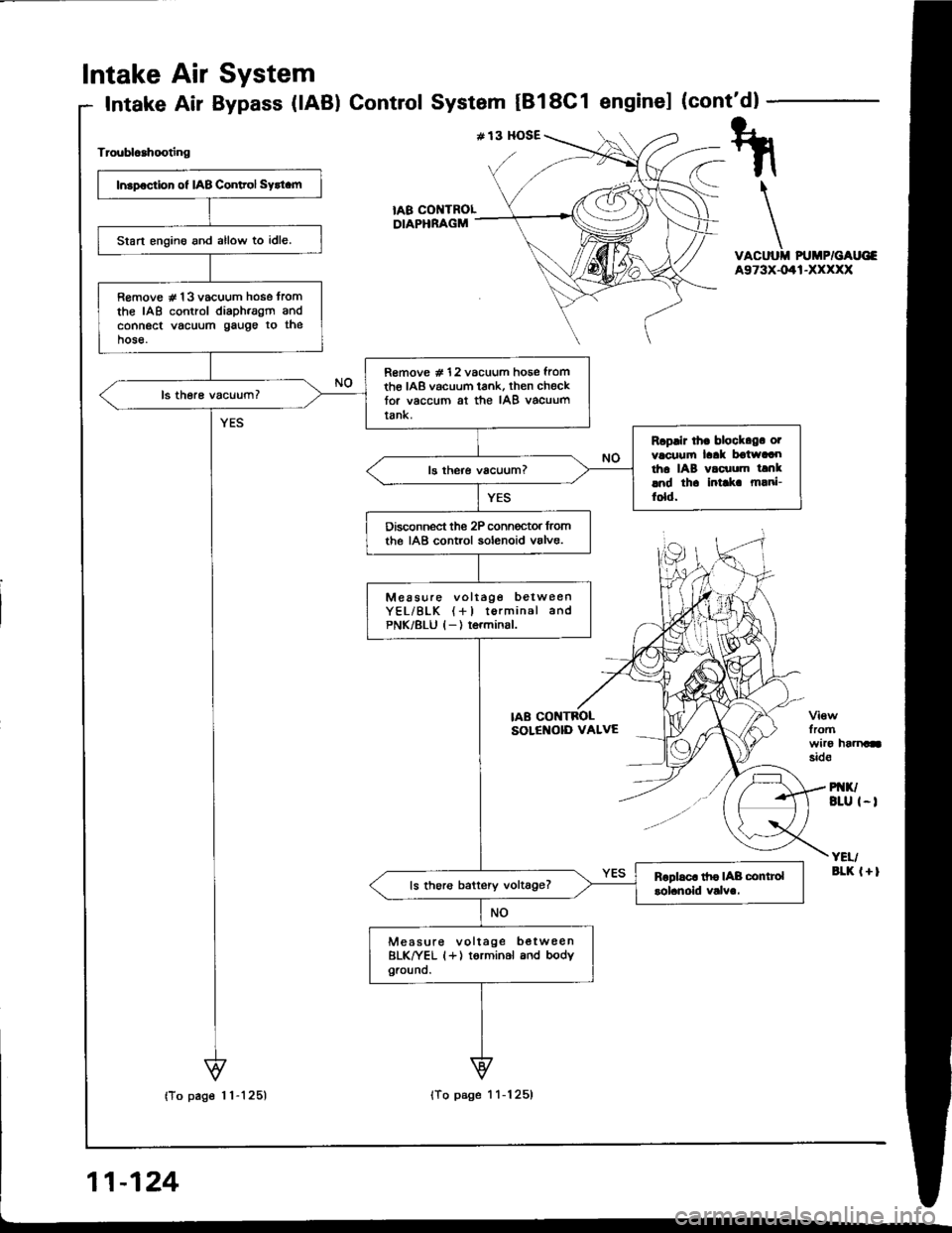
Intake
Intake
Air
Air
System
Bypass (lAB) ControlSystem tBl8C1 enginel (cont'dl
Troublcahooting
VACUUII PUMP/GAUG€A973X-041-XXXXX
fromwiro haanasid€
PI{K/BLU I-I
YEI/aLK l+l
tA8 COI{TROLDIAPHRAGM
Insp€ction of IAB Conltol Sytt.m
Start engino and allow to idle.
R€move # 13 vacuum hose tromthe IAB control diaph.agm andconnect vacuum gauge to thehose.
R€move # 12 vacuum hose fromth€ IAB vacuum tank, then checktor vaccum at the IAB vacuumtank.
Rcplir lh. block.g. otvacuufi laak boiwaaotha IAB vacuum tanklnd th. intlk m!ni-fold.
Disconnect the 2P conn€ctor lromthe IAB control solenoid valve.
Measure voltage betweenYEL/BLK (+l torminal andPNK/8LU l-) terminsl.
ls thoro battery voltage?
Measure voltage b€twee nBLK^|/EL (+) torminal and bodyground.
IAB CONTBOLSOLENOID VALVE
Page 314 of 1413
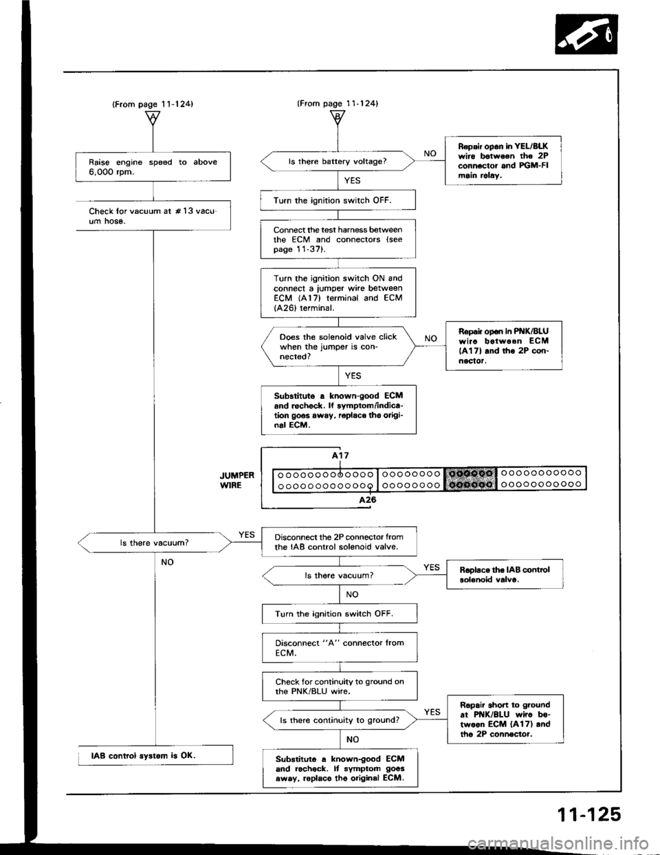
(From page 1 1-124)
Raise engine speed to above6,000 rpm.
Disconnect the 2P connector tromthe IAB control solenoid valve.
Turn the ignition switch OFF.
Check for continuity to ground onthe PNK/BLU wire.
Ropair short to g.ound
at PNK/BLU wiro bo-two6n ECM {A17) andtho 2P connector.
ls there continuity to ground?
Substituto a known-good ECMand racheck. It symptom goos
swsy, roplace tho original ECM.
{From pago 1 1-124}
Repsir op6n in YEL/BLKwiro botwoon tho 2Pconnector and FGM-FImain relaY.
ls there battery voltage?
Turn the ignition swirch OFF.
Connect lhe test harness betweenthe ECM and connectors lseepage 11-37).
Turn the ignition switch ON andconnect a lumper wke betweenECM (A17) terminal and ECM
{A26) terminal.
Ropaiiopon inP K/BLUwiao botwoen ECM
lAl7l and tho 2P con-nectot.
Ooes the solenoid valve clickwhen the jumper is con-nected?
Sub3titute a known-good ECMand rechock. lf symptom/indica-tion goos away, r6place tho origi-nal ECM.
Check lor vacuum at #'l3 vacu-um hose.
IAB control syst6m is OK.
11-125