HONDA INTEGRA 1994 4.G User Guide
INTEGRA 1994 4.G
HONDA
HONDA
https://www.carmanualsonline.info/img/13/6067/w960_6067-0.png
HONDA INTEGRA 1994 4.G User Guide
Page 1205 of 1413
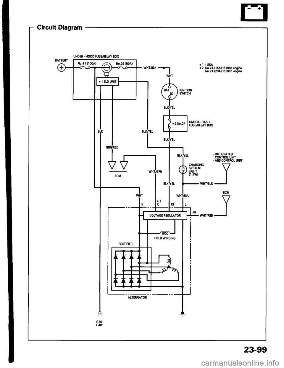
Circuit Diagram
UI,IDER - HOOD FUS€/REI.AY 8OX
*1 :USA+2 llo.24 ll SAl: 81881 .mintlo.24 {2041: 818C | .niin6
. NTEGRATEDCOMTNOL UMT. aBs coilTRor- uNn
VI
I
ECM
V
I
I
UNDER_OASHFUSE/REIAY 8OX
oiotG401
No.4t 11004) /a ilo.39l50Al
Fr€|'l) wNort'lc
AI.TERNATOR
23-99
Page 1216 of 1413
ul{o€R - DAstlGIINONSWITCH FUSC/RELAYBOX
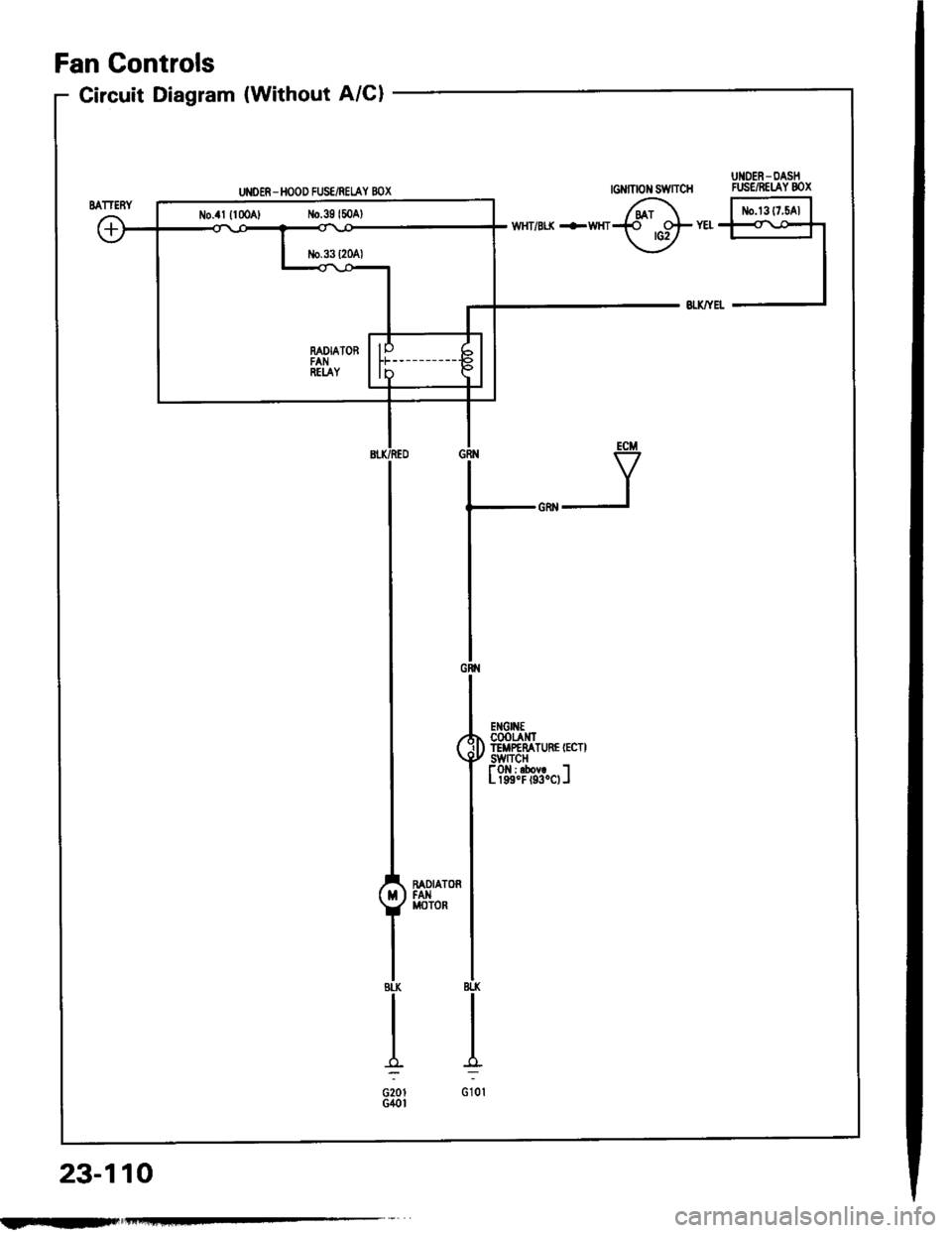
Circuit Diagram (Without A/Cl
UI{OER - HOOD FUS€/REI.AY BOX
6r F'rrr^'l.{ ots YEt {<\o*r
\-Y -l
ECM
V
Gtr{
l,*^,
($fffiHil'r"n.''
I
t?i'r?Tdf.ol
I
ffi,"'l
IBtl(
I
I:
G10l
Fan Controls
23-110
No.4l {lmA, No.39l50Al
FIIF.-
Page 1217 of 1413
G FION SWIICH
No.41 l100Al No.39l50At
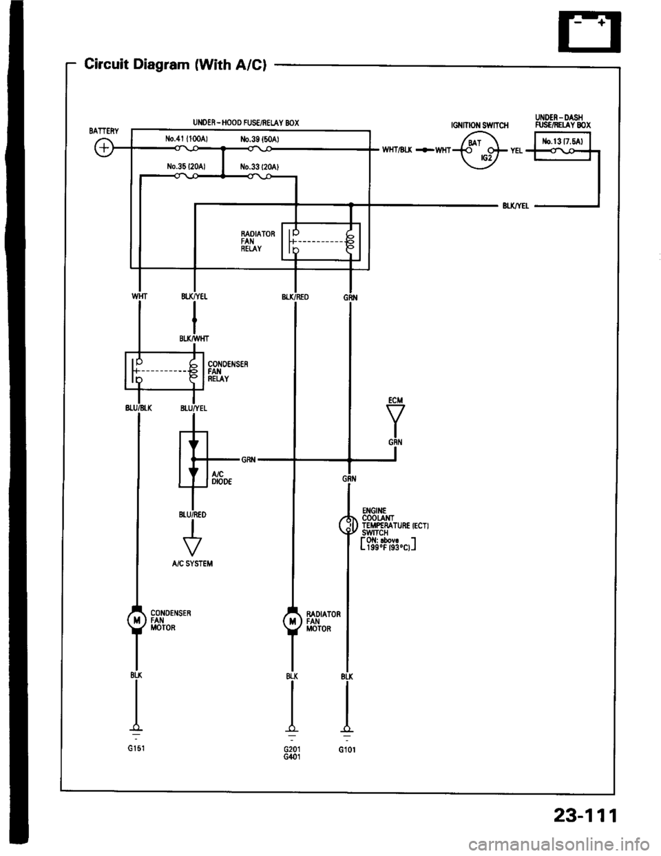
RAOIATORFANREI.AY
Gircuit Diagram (With A/Cl
UNOER - HOOO FUSE/REIAY BOX
,5
GRt{
| ,*n,n,,z*r CoOtAt{TqU llffffarunErEcrr
I
t?i'i."1",i:"ol
Imonron IFAN IMOTOR
I
IBI-K
I
I:
G10l
23-111
Page 1222 of 1413
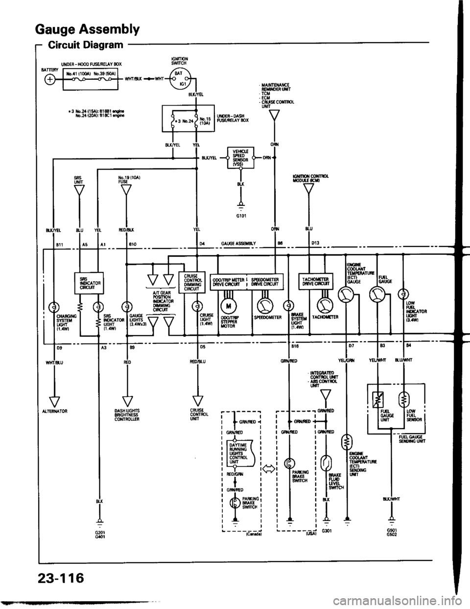
Gauge Assembly
Gircuit Diagram
r3 [o.24 ll5 ): 81E81 dttr10,24120 ):B1&1.mirulocn-D sHRISC/RELAY &X
Tw'lcu I
+ 3r,4ts. rt_gstr
Il{l(
IA:6t0l
sastNtT
T
FUSE
snstxocAloRUGTIT[fffi"vv
N'ElGAI.EEsExDr6 ulllT
.lsffiisl{,MT
VI- r Gin&no
".lJrlI C,afi/ilD
ilrlrl
in- | ()" | | snrxt. r I Rlp
i |ffi.rlItrr
rl
iAt:
r6ii G30r
GMVn!O
#nI RUNIiITG II uGfiTs \
l8flfl*' ;
ht0/Git{
IGn[/Ft0
6mii'
I-
a{G|l|€c@lat{TIl$EiA'l iltErcTtSAdTGtxt
23-116
Page 1232 of 1413
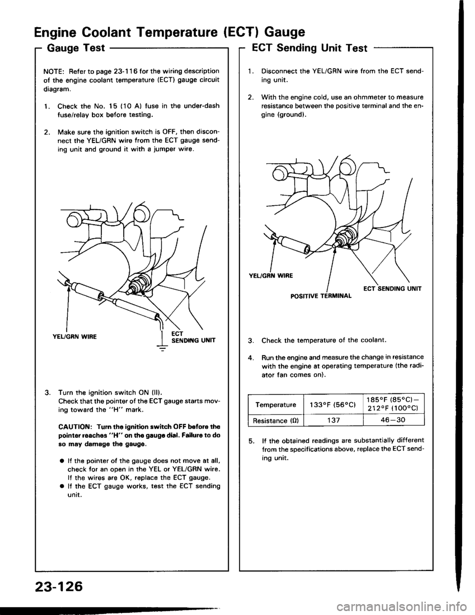
GaugeTest
NOTE: Refer to page 23-116 fot the wiring description
oJ the engine coolant temperature (ECT) gauge circuit
diagram.
1. Check the No. 15 (10 A) fuse in the under-dash
tuse/relay box before testing.
2. Make sure the ignition switch is OFF, then discon-
nect the YEL/GRN wire from the ECT gauge send-
ing unit and g.ound it with a jumper wire.
Turn the ignition switch ON (lll.
Check that the pointer of the ECT gauge starts mov-
ing toward the "H" mark,
CAUTION: Tuln th6 ignition switch OFF botore th€
point reaches "H" on tho gaugo dial. Failuro to do
so may damago tho gaugo.
a It the pointer of the gauge does not move at all,
check Jor an oDen in rhe YEL or YEL/GRN wire.
lf the wires are OK, replsce the ECT gauge.
a It the ECT gauge works, test the ECT sending
untt.
J.
Engine Coolant Temperature (ECTI Gauge
ECT Sending Unit Test
Disconnect the YEL/GRN wire from the ECT send-
ing unit.
With the engine cold, use an ohmmeter to measure
resistance between the positive terminal and the en-
gine (ground).
Check the temperature of the coolant.
Run the engine and measure the change in ,esistance
with the engine ai operating temperatu.e {the radi-
ator tan comes on).
5. ll the obtained readings are substantially different
Jrom the specifications above, replace the ECT send-
ing unit.
23-126
POSITIVE TERMINAL
Temperatu.e1330F (560C)185.F (850C)-
2120F (1000c)
Resistance (O)'t3746-30
Page 1236 of 1413
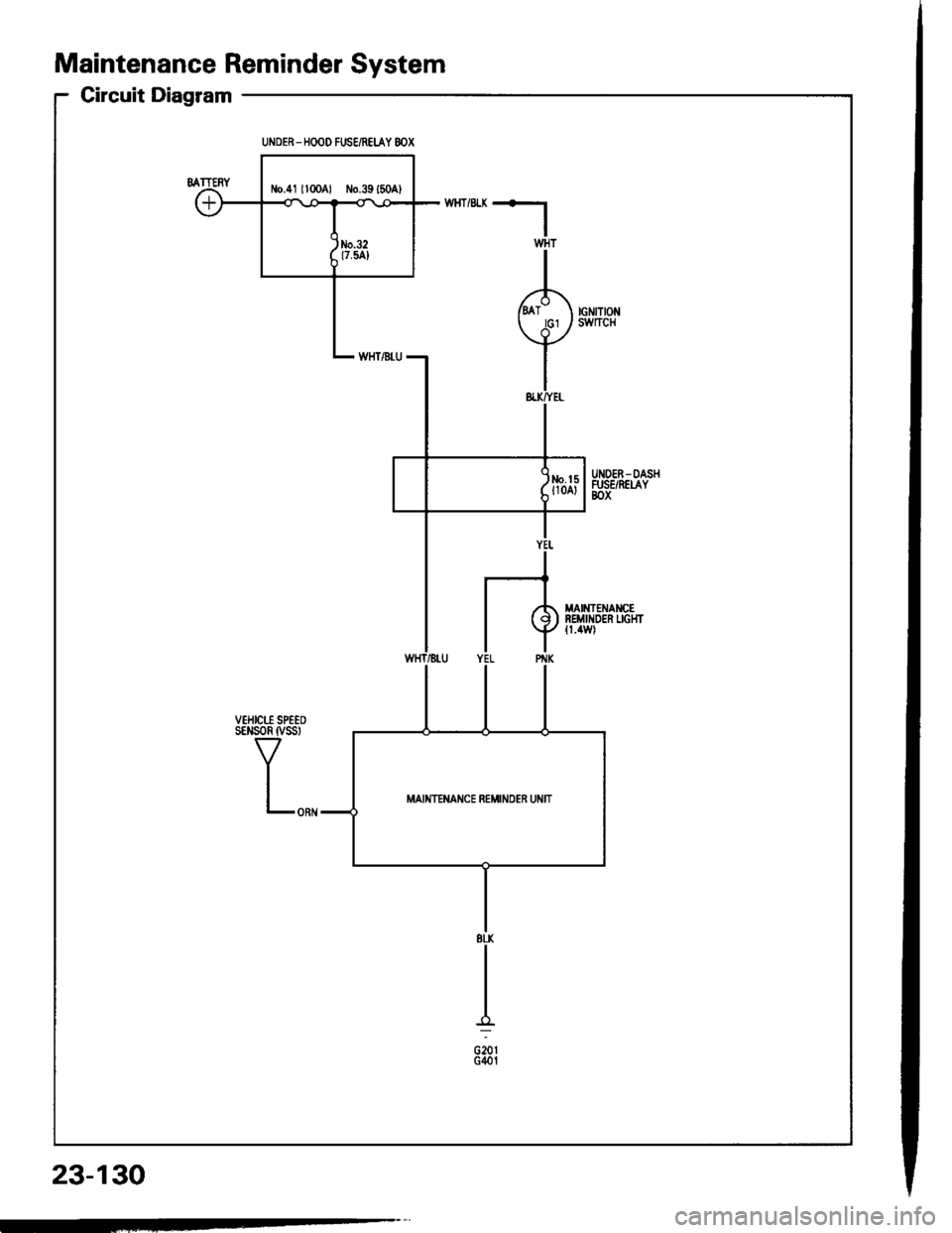
Maintenance Reminder System
Circuit Diagram
23-130
UNDER-HOOD FUSE/REIAY 8OX
MAINIET,IAT,ICE REMINOER UiIIT
Page 1239 of 1413
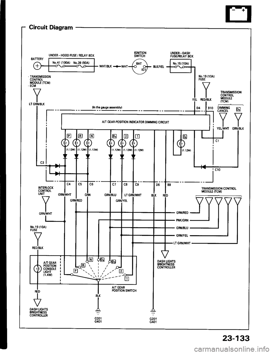
UNOER_HOOD FUSE / REI.AY 8OX
Circuit Diagram
IGNITIONswrTcHUNOER-OASHFUSSREI-AY 8OX
No.19ll0A)FUSE
TMI{SMrSSr0r,lc0IJTRori.IODULEITCMI
fitMritc-;-CANCEL lgll
tlYELTWHT GRN/8L|(
D4
II._l
TRANSMISSIONMODU|.! [TCM}
t
INTERLOCKcoMtRotUNJ]_
IGRT'IMHTo*nn,o_yTT
pr{x/cR1 -J
IGR €|-U -l
GRiITYEt
LT GNNiW{T
No.19 {lFUSE
V
I
I
DASH I-IGHTSBRIGHTNESSCONTROI.IERG2o lG401
I
G201G40t
/-?t ftrt*lwHT/BLX +wHT+ CH- Bl.x/Y€t -+<.\-o+!
y "l
IYEL
lln tho gtugo 8ls€mbvl
AN GEAR POSITION INDICATOR DIMMING CIRCUIT
A/T GEANPOStTt0NcoNsot-ELIGHT0.4w)
M GEARPosrTroN swncH
23-133
Page 1246 of 1413
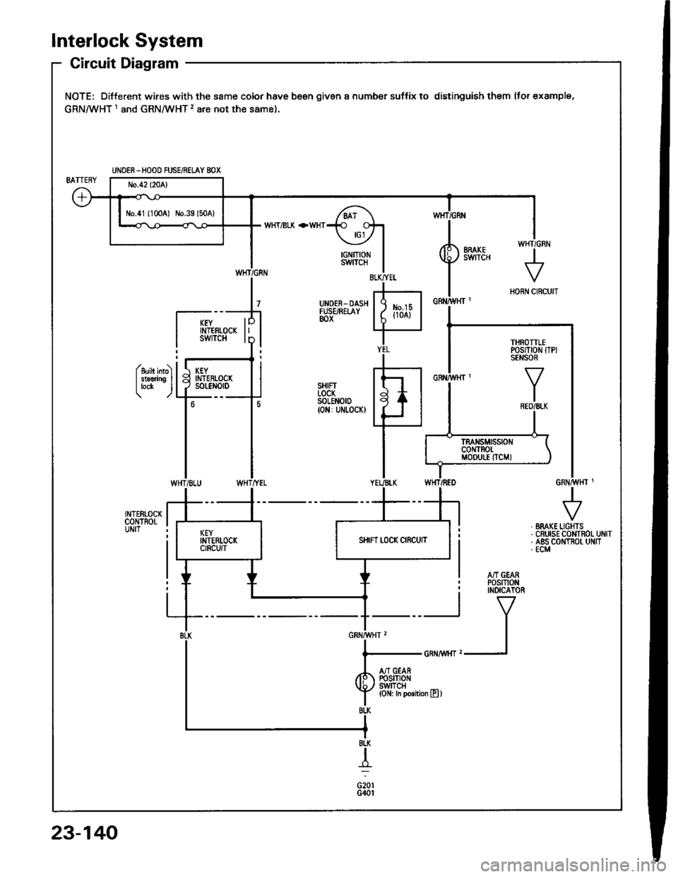
lnterlock System
Circuit Diagram
NOTE: Different wires with the same color have been given a number suffix to distinguish them (tor examplg,
GRNMHT 1 and GRNMHT 2 are not the same).
W}IT/BLK +WHT
Y I if,f,trfi
I i
^'v"'
IIN/vt,H] ,
I
l......................_GRNA,t/r{rz1
/r S'ftiei
f lJlT,ll*n""n,
UNOER -HOOD FUSE/REi.AY BOX
N0.41 (1OCA) No.39 l50A)
THROTTLEPOSITION ITPISENSOR
WHT/GRN
23-140
Page 1250 of 1413
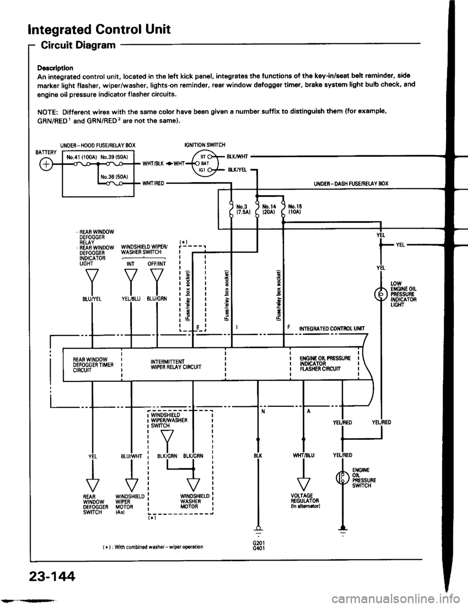
Integrated Control Unit
Circuit Diagram
D.3c ptlon
An integrat€d control unit, located in the left kick panel, integratss the functions of tho keyin/seat beh r6mind€r, sido
markar light {lasher, wiper/washer, lights-on r6minder, rear window dsfogger timer, brak€ system light bulb check, and
enging oil pressure indicator flasher circuitE,
NOTE: Difforent wires with the same color have be6n given a numbor suffix to distinguish them (for Example,
GRN/RED1 and GRN/RED'� are not the same).
WNOSHIELD WIPER/WASHER SWITCH
IMT OFFiINT
I
II
IIIIIIIIIIII
YEUEE
rl
t
P
UNOER - DASH FUS€/RETAY BOX
r NTEGRATED COI{TROI UNIT
t-0wErGrilE 0|lPRESSI'REINDICATORLIGI{T
WINDSHIELOWIPERAVASHERswtTcH
tr-/
IBLK/GRN BI
WINDSHIELOWIPERMOTOR{Asl
VOLTAGEREGULATOR{ln ahamator,
UNOER- HOOD FUSE/RELAY 8OX
I
r3
r8relit;rBt5I
23-144
lr ) : With combinod washef-wip€r oporation
Page 1256 of 1413
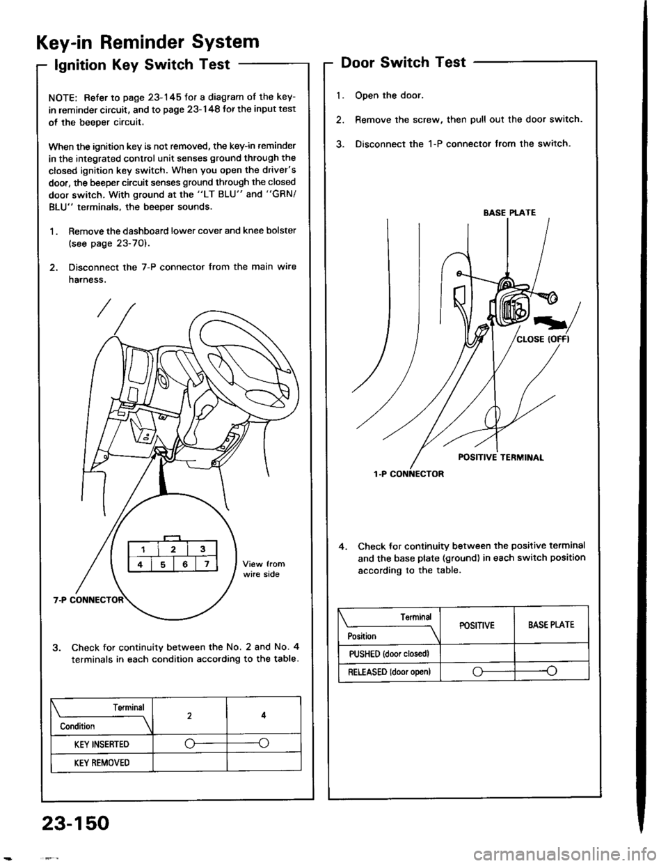
Key-in Reminder System
lgnition Key Switch Test
NOTE: Refer to page 23-145fot a diagram of the key-
in leminder circuit, and to page 23-148 Jor the input test
ol the beeper circuit.
When the ignition key is not removed, the key-in reminder
in the integrated control unit senses ground through the
closed ignition key switch. When you open the driver's
door, the beeper circuit senses ground through the closed
door switch, With ground at the "LT BLU" and "GRN/
BLU" terminals, the beeper sounds.
1 . Remove the dashboard lower cover and knee bolster
(see page 23-70).
2. Disconnect the 7-P connector from the main wire
harness.
Check for continuity between the No. 2 and No. 4
terminals in each condition acco.ding to the table.
l.
Door Switch Test
Open the door.
Remove the screw, then pull out the door switch.
Disconnect the 1-P connector from the switch.
4. Check lor continuity between the positive terminal
and the base plate (ground) in each switch position
according to the table.
BASE PLATE
Position
TerminalPOSITIVEBASE PLATE
PUSHED {door closedl
RELEASED ldoor o!en)oo
Terminal
Condition
4
KEY INSERTED--o
KEY REMOVED
23-150
