HONDA INTEGRA 1994 4.G Owner's Manual
INTEGRA 1994 4.G
HONDA
HONDA
https://www.carmanualsonline.info/img/13/6067/w960_6067-0.png
HONDA INTEGRA 1994 4.G Owner's Manual
Page 1257 of 1413
Engine Oil Pressure
Indicator System
Description
NOTE: Reter to page 23-144 tor the circuit diagram otthe engine oil pressure indicator flasher, snd to page
23-148 lor the input test of the flasher circuit.
The low engine oil pressure indicator tight works in twoways. lt will flash continuously following a momentaryloss of oil pressure, or it will go on and stay on with acomplete loss of oil pressure.
When the engine first starts, before oil Dressure risesabove 29.4 kP8 10.3 kgf/cmr, 4.3 psi), current flowsthrough the low engine oil pressure indicator light andthe oil pressure switch to ground. This tests the circuit.
Wilh the engine running, voltage is applied ro the ftash-er circuit of the integrated control unit. With normal oilpressure, the oil pressure switch is open and the low en-gine oil pressure indicator light does not operate. lf theoil pressure switch closes momentarily (more than O.5secondsl, but then opens again, terminal "yEL/RED,'will
sense ground through the switch. The integrated con-trol unit willthen provide and remove ground for th€ lowengine oil pressure indicator light through terminal"YEL/RED". The light will flash on and olf until the igni-tion switch is turned to "OFF".
lf engine oil pressure falls below 29.4 kPa (O.3 kgJ/cmr,4.3 psi) and does not increase, the oil pressure switchwillstsy closed. The low engine oilpressure indicator lightwill go on and stav on.
NOTE; Refer to page 23-122lot the engine oil pressure
switch test.
Lights-on Reminder
System
Description
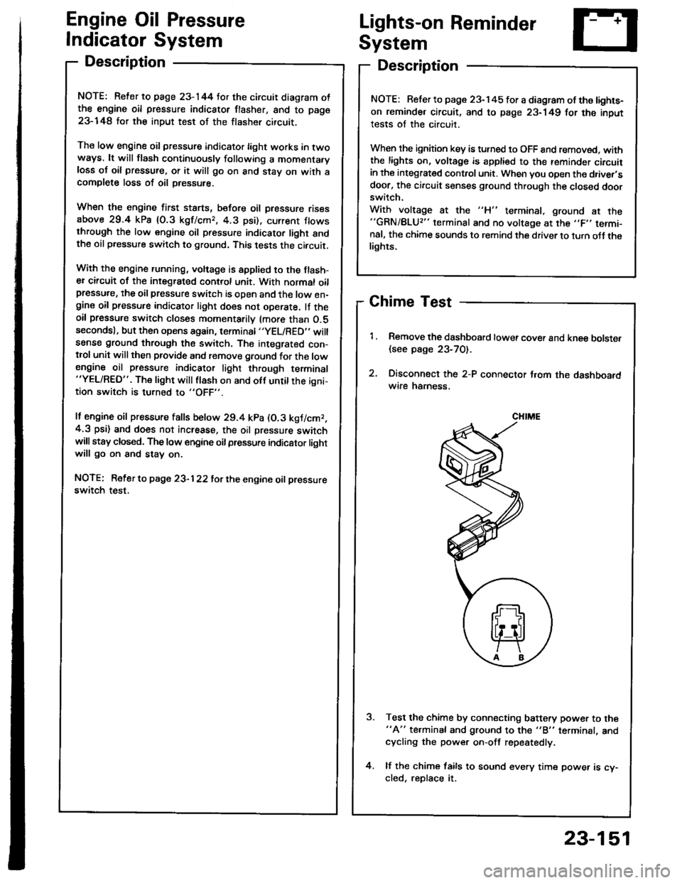
Chime Test
Remove the dashboard lower cover and knee bolster
{see page 23-70).
Disconnect the 2-P connector t.om the dashboardwire hamess.
Test the chime by connecting battery power to the"A" te.minal and ground to the "B" terminal, andcycling the power on-off repestedly.
lf the chime fails to sound every time power is cy-cled, reDlace it.
NOTE: Refer to page 23-145 tor a diagram of the lights-
on reminder circuit, and to page 23-149 for the input
tests of the circuit.
When the ignition key is turned to OFF 8nd removed. withthe lights on, voltage is apptied to the reminder circuitin the integrat€d control unit. When you open the driver,sdoor, the circuit senses ground through the closed doorswitch.
With voltage at the "H" terminal, ground at the"GRN/BLU2" terminal and no voltage at the ,,F,' termi-nal, the chime sounds to remind the driver to turn oJf thelights.
CHIME
23-151
Page 1260 of 1413
Lighting System
Circuit Diagram (USAI
UNOER - HOOD RJSE/NELAY 8OX
-r lo| ,-. otFDIMMER I'I
No.2l|l0A]iil;
)
ttNo.lo '1 No,22 ''t No.gtloAr (0oA) (floAr
IT
HEADLIGHTRIGHTHEAOUGHT
HIGH EEAMINOICATORLIGHTfi.4W)@il,", @f,*,6il* 6p*
. PAR(II{G UGHI. TAILUGI{TS. UCENSE PI.ATE
UtrloER - D SHRJSE/RELAYsox
REO/GNN
8LK
I
G20lG401
DASH UGI{TS88rGr{T ESSCONTrcUTRDASH UGHTSPAR(II{C UGHTSTAItUGt{TSUCENSE PI.ATEUGHTS
8tK
G301G20'�|G40l
23-154
Page 1261 of 1413
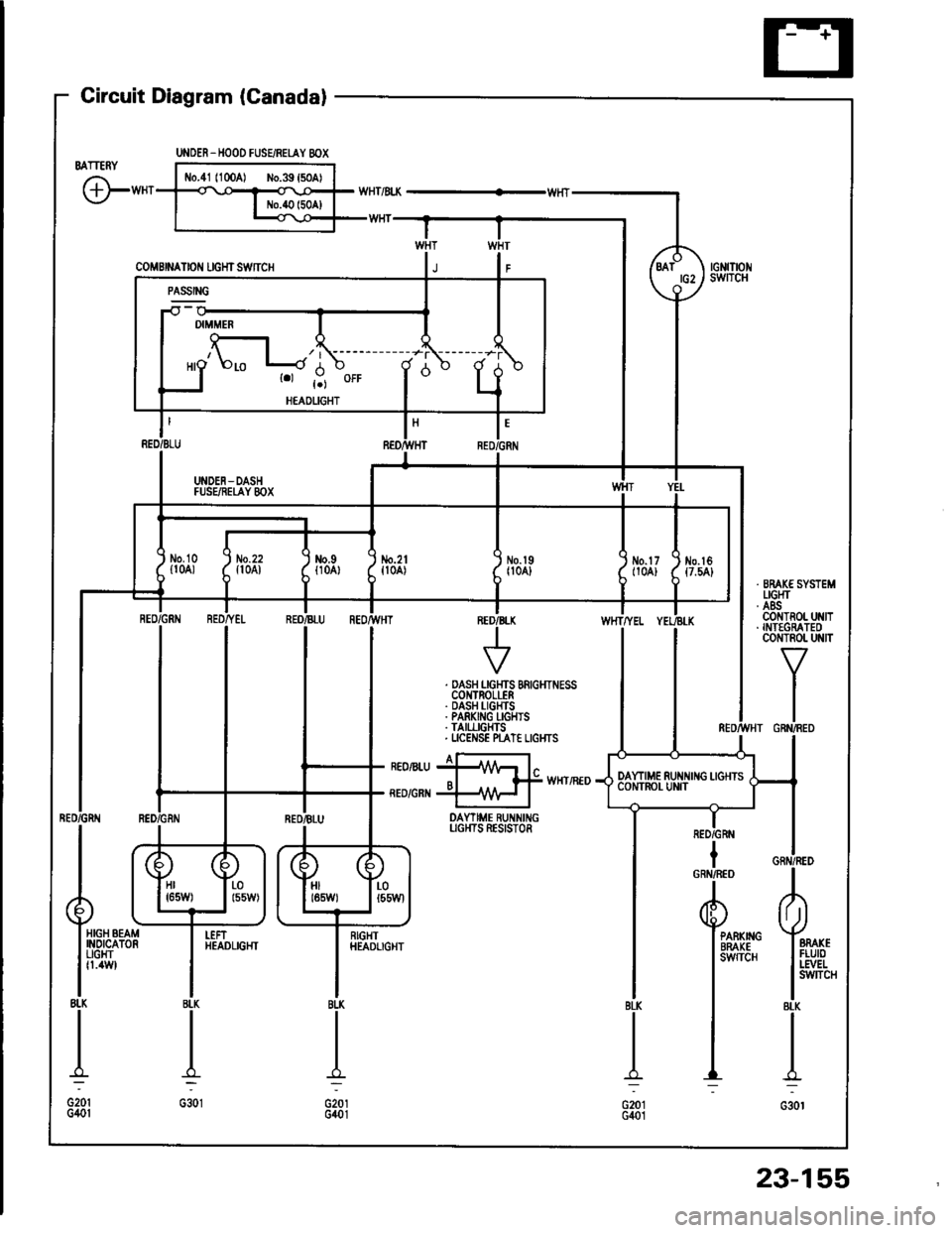
Gircuit Diagram (Canadal
BATTERY
G"*
UNOER_HOOD FUSEiRETAY 8OX
coMBrNAtor{ rcHrswnc
-il w
| '.=r" I
ll'L I I
I I *o\." l-'li' ;- ;j
I LI
"- r.r-,9 "orr
I
d "
L
RED/BLU REO/}VHT RED,ll
I UNDEN-DASH II FUSEiIEI,AY 8OX I
tl
L-J
t'GRN
/d\BATtG2\9-l
rGNrTrot{swITcH
No.2lfl0A)\I
No.l9|l04]Jm.tr (
t10A) ttt
I
No.l6{7.54}
tl
i,"#
llrrff li'rrt,
RED/GRtIIBLU REOr'TVHTINED/B
V
WHTTYEL
. DASH LGHTS BRIGHTNESSCOI{TROLLER. DASH I-IGHTS. PARKING I-GHIS. TAII,LIGHTS. UCENSE N"AT€ LIGI{TS
I a-rneonru jllA/Vr l"o I f# wxrintoRED/GRI{ +\{H I
DAYTIME RUNNINGUGI{TS RESISTOR
IRED/GRN
Hr I r-01651,1/) | l55W)HIt85W)LOt55Wl
HIGH BEAMINOICATORUGHTfl.4W
I
RIGHTHEADLIGHTPARKIIIGBRAKEsw{TcH
23-155
Page 1276 of 1413
UNDER. HOOD FUSE/REIAY 8OX
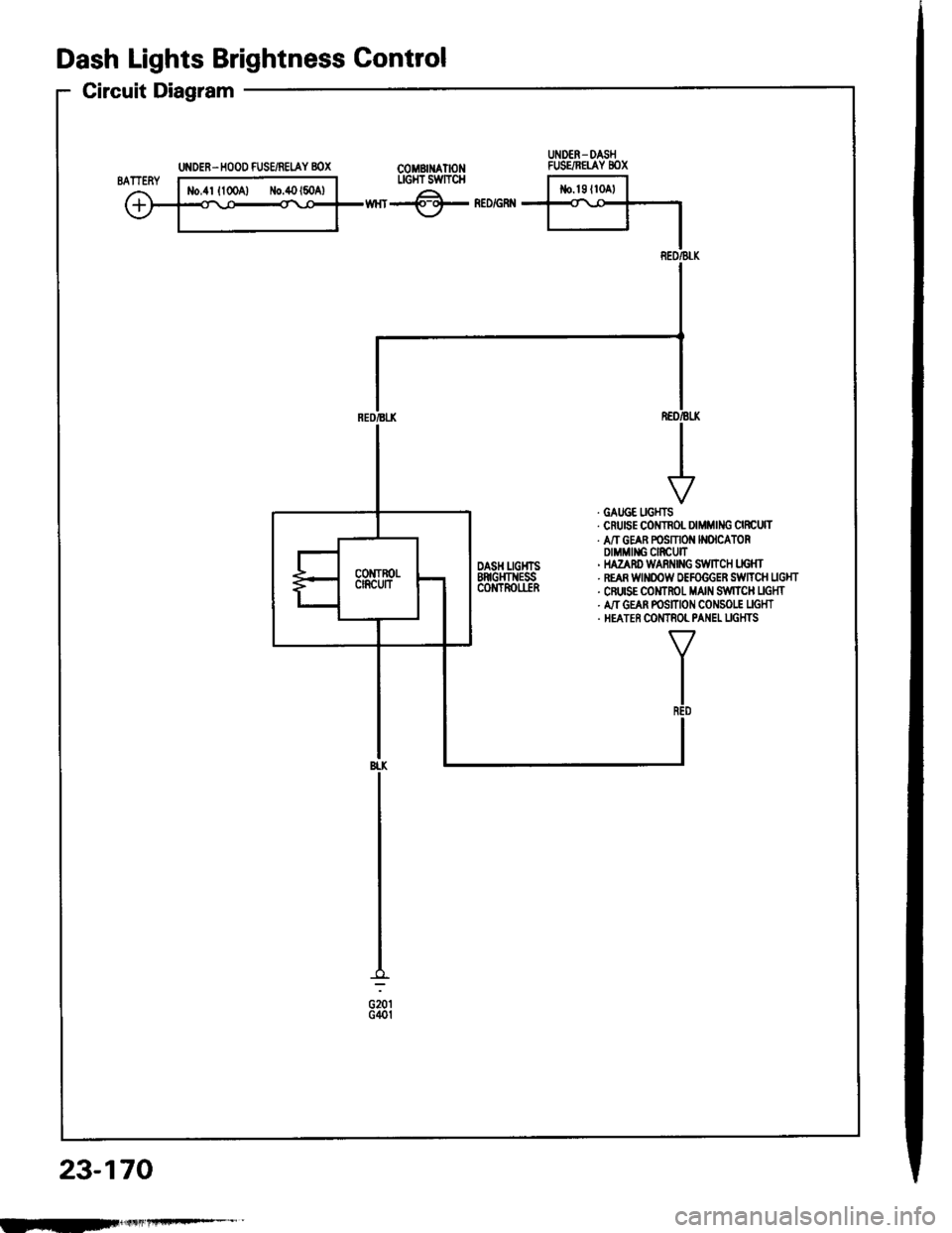
Dash Lights Brightness Gontrol
Circuit Diagram
COMBII{ATIONLIGI{T SWTTCH
wnr-@- neorenn
REO/BLK
. GATJGE UGHTS. CruEE COITNOL DIMMING CIRCUTT. A/T GEAR POSMON N(ICATORDIMMII{G CIRCUIT' HAZAnD WARi{|NG S:WltCH LIG}fr. REAR WINOOW OEFOGGER SiWTTCH UGHT. CFUISE COMTROT MAIN S,IVITCH UGHT. A,IT GEAN POSITION CONSO|.! UGHT. HEATER COMTNOL PANEL UGHTS
TR€D
BI.K
G201G40t
23-170
UNDER- DASHFUSE/NETAY 8OX
IEF
Page 1279 of 1413
FROiTTPASSEiIGEB'SDOOf,SWTCH
GRr{/Bt U t-t
I
q*",,.,
I DOOR
I swncH
I
I:
U DEN-DASHFUSE/RELAY 8OX
LT
II{IEGRATED 1cotlrnor II,NIT I
GRI{
I
l**,-0,,nI rNorcAToRI UGHT
IY
i'GRN
d_
f-:
J
23-173
lS.d.nl
TBUi{KUGHTt3.4Wl
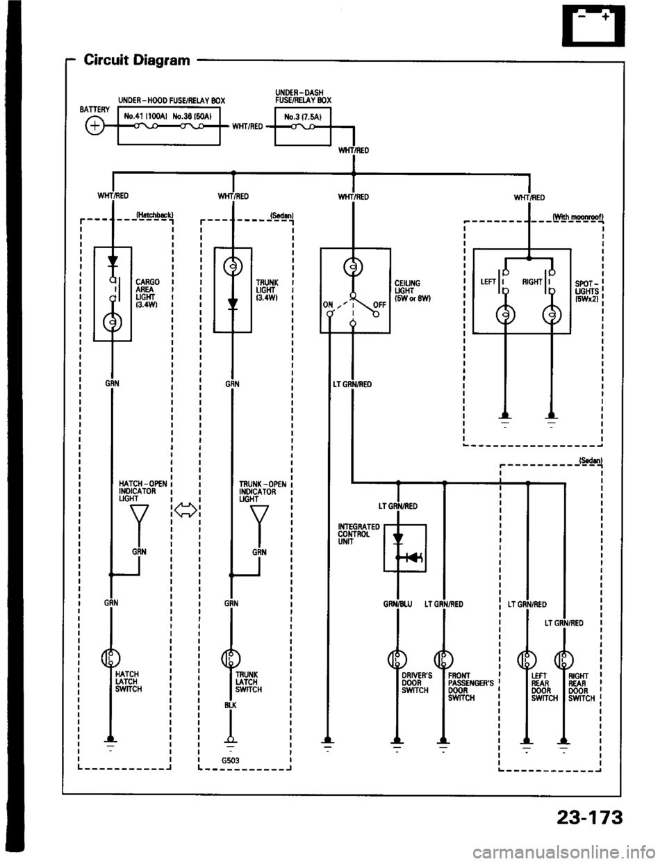
Circuit Diagram
Hltcnb&n-------1
CARGOASEAUGHTt3.4Wl
UNOER - HOOD FUSE/RELAY 8OX
Page 1285 of 1413
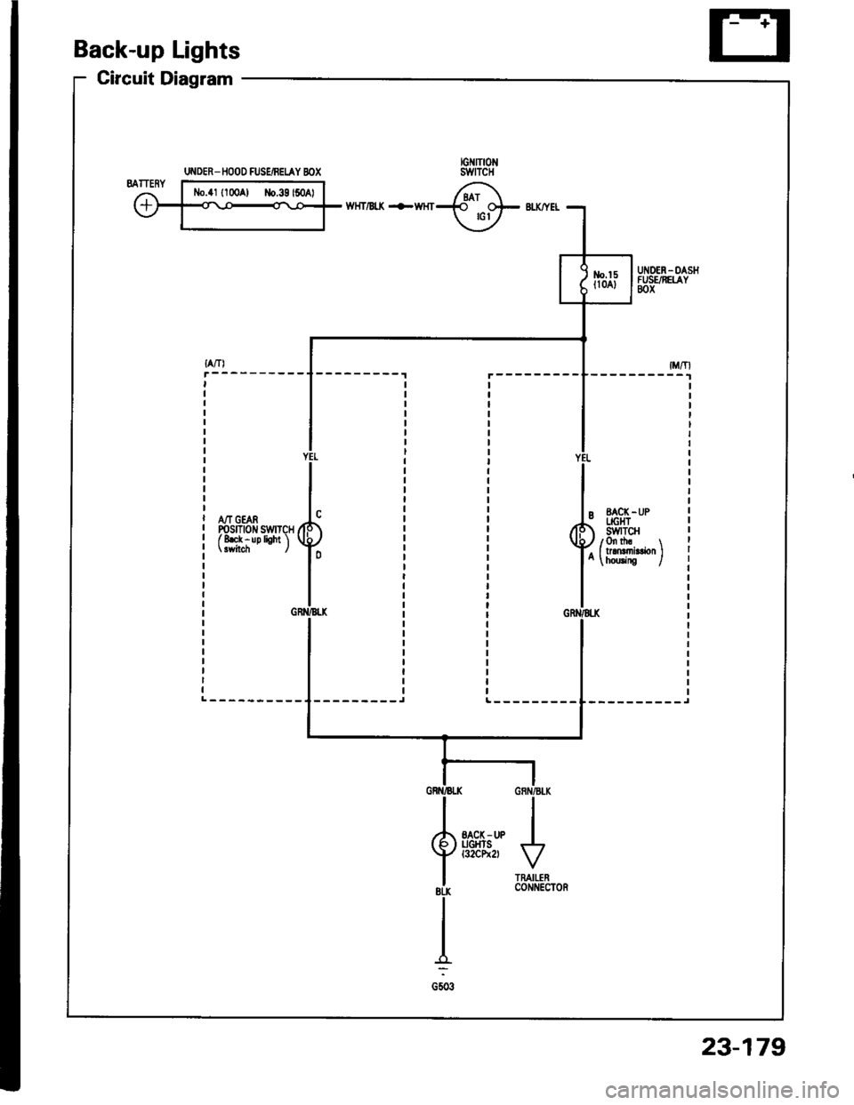
Back-up Lights
Circuit Diagram
wHT/Bt( +WHT
A/T GEARPosrnotr swrTcHf 8ek - up lioht 'l
--------_JL---------
UI{DER_ IIOOO FUSEiBEIAY BOX
23-179
Page 1287 of 1413
Circuit Diagram
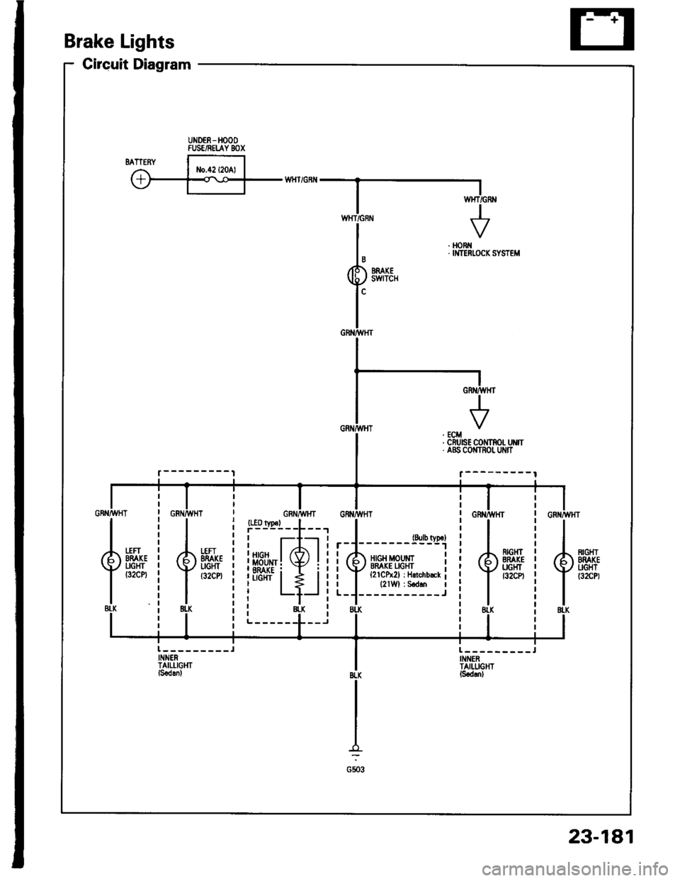
Brake Lights
UNDEE-HOOOFUSE/NELAY BOX
. HORi{. IMTERI.OCK SYSTEM
{.BLK
*H-i
{.{u8tK
23-181
Page 1291 of 1413
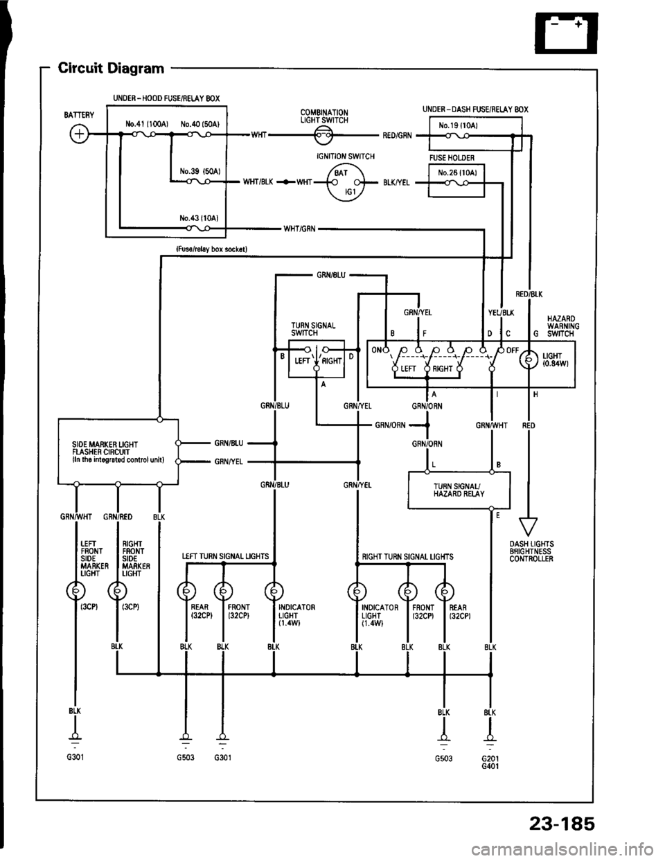
UNDEN-HOOD FUSE/RELAY 8OX
N0.41 1100A) No.40 (50A)
Gircuit Diagram
COMBINATIONLIGHTSWTCHA.---of-RED/GRN
IGNITION SWITCH
/6i\WHT/BTK +WHT+ +- BIK/YET
\jv
UNDER-DASH FUSE/RELAY 8OX
FUSE HOTJER
GRN/BtU
TURN SIGiIALswtTcH
I
|l
+DASH TIGHTSBRIGHTNESSCONTROLLER
SIOE MAFKER LIGHTFLASHER CIRCUITlln tho intogruted controlunitl
RIGHT TURN SIGNAT TIGHTS
INOICATOR I FRONT I REARL|GHT I t32CD I t32CPl(1.4W1
23-185
Page 1296 of 1413
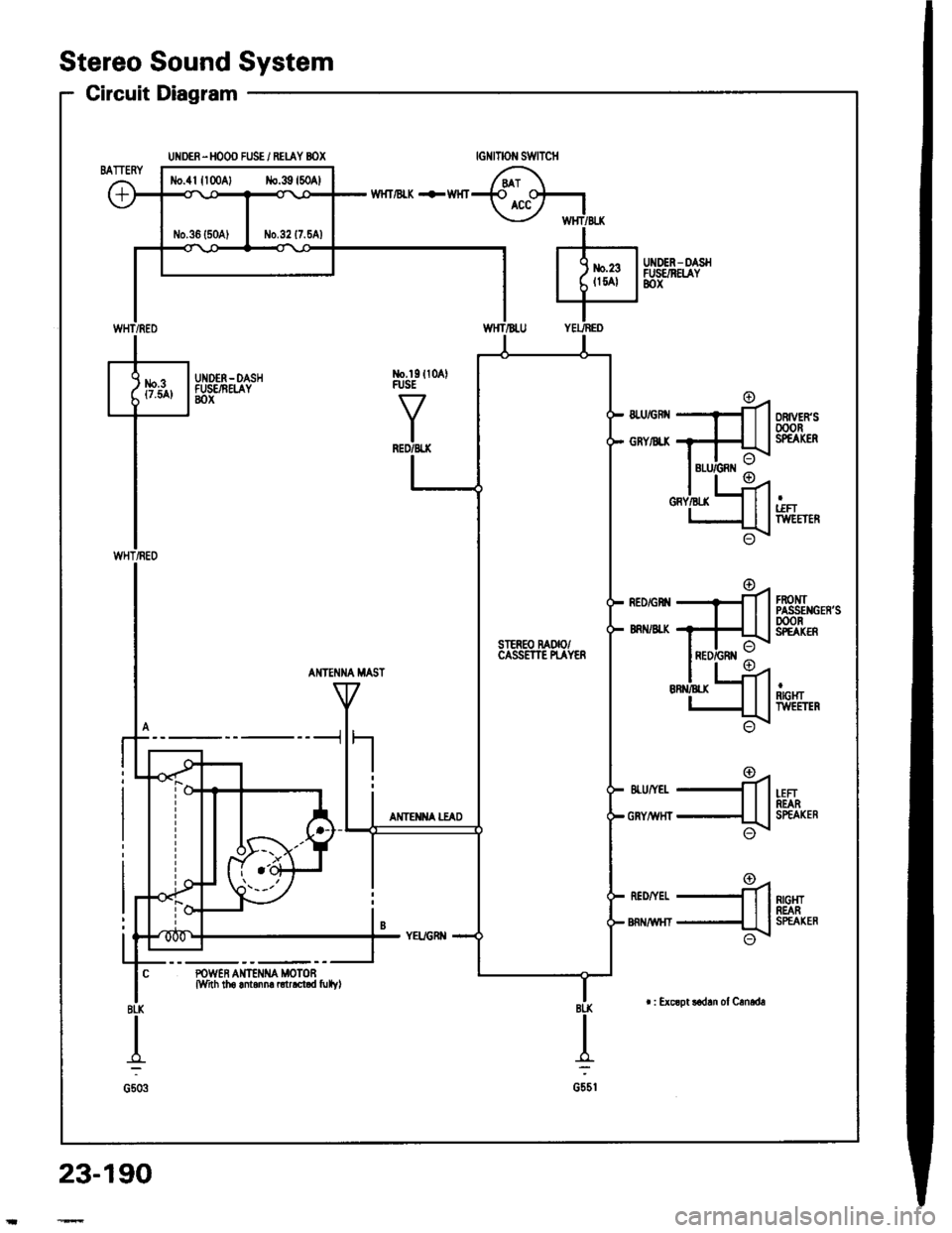
tlo.4lllo0Al No.39l50Al
SIER€O MOOCASSETTE N.AYER
Stereo Sound System
UNDER-HOOO FUSE i RETAY BOX
Circuit Diagram
UNDEN-DASHFUSENEIAY8ox
tGNtTOt{ SWTTCH
WHT/BI"K +WHT
No.l9ll0AlRJSE
AI{TE?{NA MAST
-L-fl
4
-fi1
.a'J
POWER AIT€NI{A MOTOFM_nh tho antanna ntrrct d fulvl
AMTEI{iIA ITAD
RIGI{TREARSPEAXER
23-190
| : Excoot !ad!n of Crnede
Page 1303 of 1413
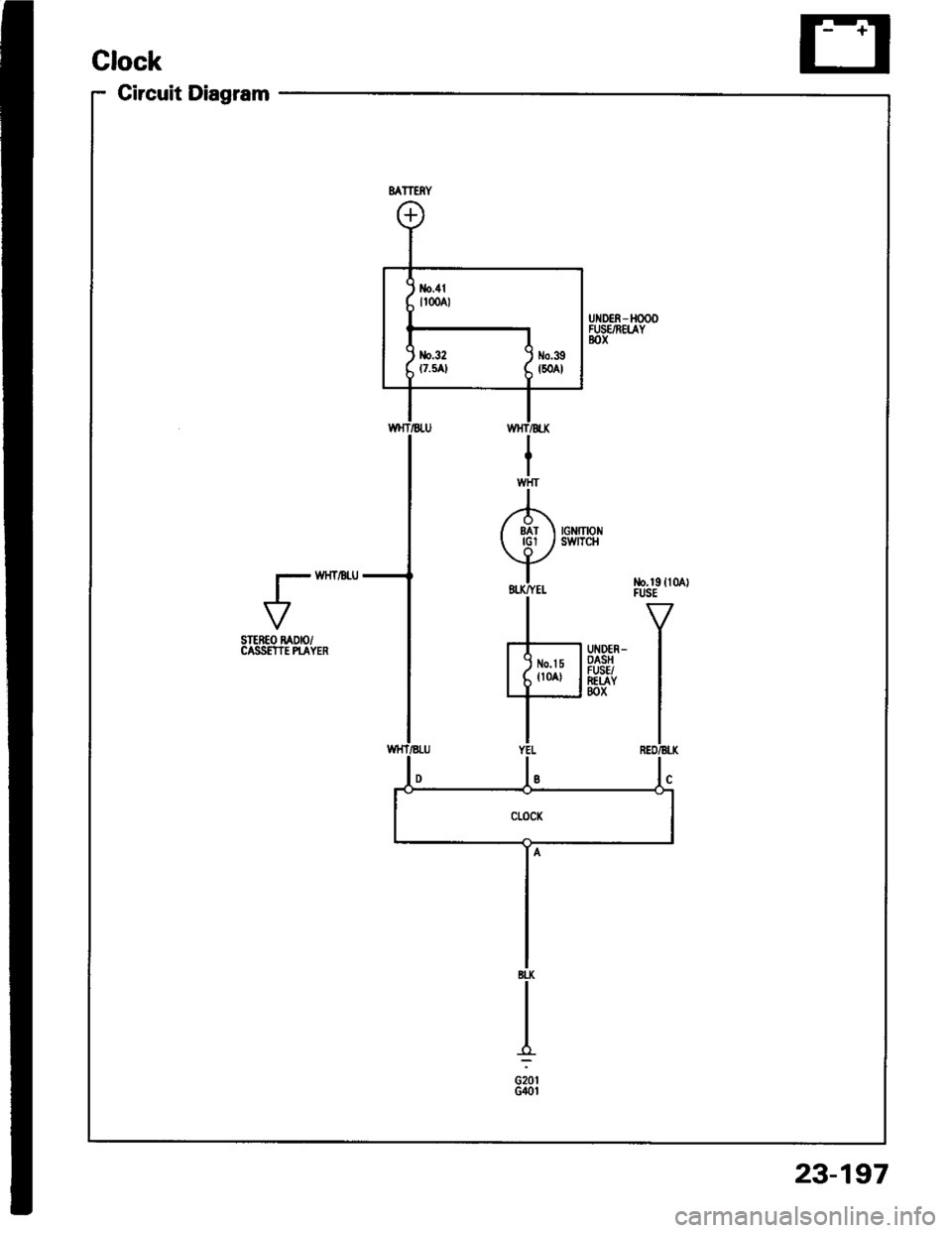
Circuit Diagram
VSTEREO RADIO/CASS€TIE PI-AYER
23-197

![HONDA INTEGRA 1994 4.G Owners Manual Lighting System
Circuit Diagram (USAI
UNOER - HOOD RJSE/NELAY 8OX
-r lo| ,-. otFDIMMER II
No.2l|l0A]iil;
)
ttNo.lo 1 No,22 t No.gtloAr (0oA) (floAr
IT
HEADLIGHTRIGHTHEAOUGHT
HIGH EEAMINOICATORLIGH HONDA INTEGRA 1994 4.G Owners Manual Lighting System
Circuit Diagram (USAI
UNOER - HOOD RJSE/NELAY 8OX
-r lo| ,-. otFDIMMER II
No.2l|l0A]iil;
)
ttNo.lo 1 No,22 t No.gtloAr (0oA) (floAr
IT
HEADLIGHTRIGHTHEAOUGHT
HIGH EEAMINOICATORLIGH](/img/13/6067/w960_6067-1259.png)
