display HONDA INTEGRA 1994 4.G User Guide
[x] Cancel search | Manufacturer: HONDA, Model Year: 1994, Model line: INTEGRA, Model: HONDA INTEGRA 1994 4.GPages: 1413, PDF Size: 37.94 MB
Page 1037 of 1413
Heater and Air Conditioning
Heater ........ 21-1
Air Conditioning .......... ..22-1
SUPPLEMENTAL RESTRAINT SYSTEM {SRS}
The Integra SRS includes a driver's airbag, located in the steering wheel hub. In addition. all models except the
RS model for Canada have a front passenge.'s airbag located in the dashboard above the glovs box. Information
necessary to safely service the SRS is included in this Service Manual. ltems msrk€d with an asterisk (') on the
conlents page include, or are located near, SRS components. Servicing, disassembling or,eplacing thes€ items
will require special precautions and tools, and should therefore be done by an authorized Acura dealer.
a To avoid r6nd6dng tho SRS inoporativo. which could lead to personal injury or dealh in tho svont ot a sevele
frontal collision, all SRS servica work musl b€ portormed by an authorized Acura dealer.
a lmpropor sorvico procaduro3, including incorrect romoval and installatlon of tho SRS, could load to porsonal iniu-
ry causod by uninlonlional activation of tho ailbag8.
a All SRS eloctdcal widng harnossos are covored with yollow in3ulation. Relatsd compononts a.o locatod in tha
stsering column, flont console, daehboard, and dashboafd low6r pan6l, and in lhe dsshboa.d above lh€ glove
box. Do not uao electdcal tost equipmont on theae circuhs.
NOTE: The original radio has a coded theft protection circuit. Be sure to get the customer's code number beto.e
- disconnecting the battery.- removing the No. 32 (7.5 A) luse from the under-hood fuse/relay box.- removing the radio.
After service, reconnect power to the radio and turn it on. When the word "CODE" is displayed, enter the cus-
tomer's 5-digit code to restore radio operation.
Page 1039 of 1413
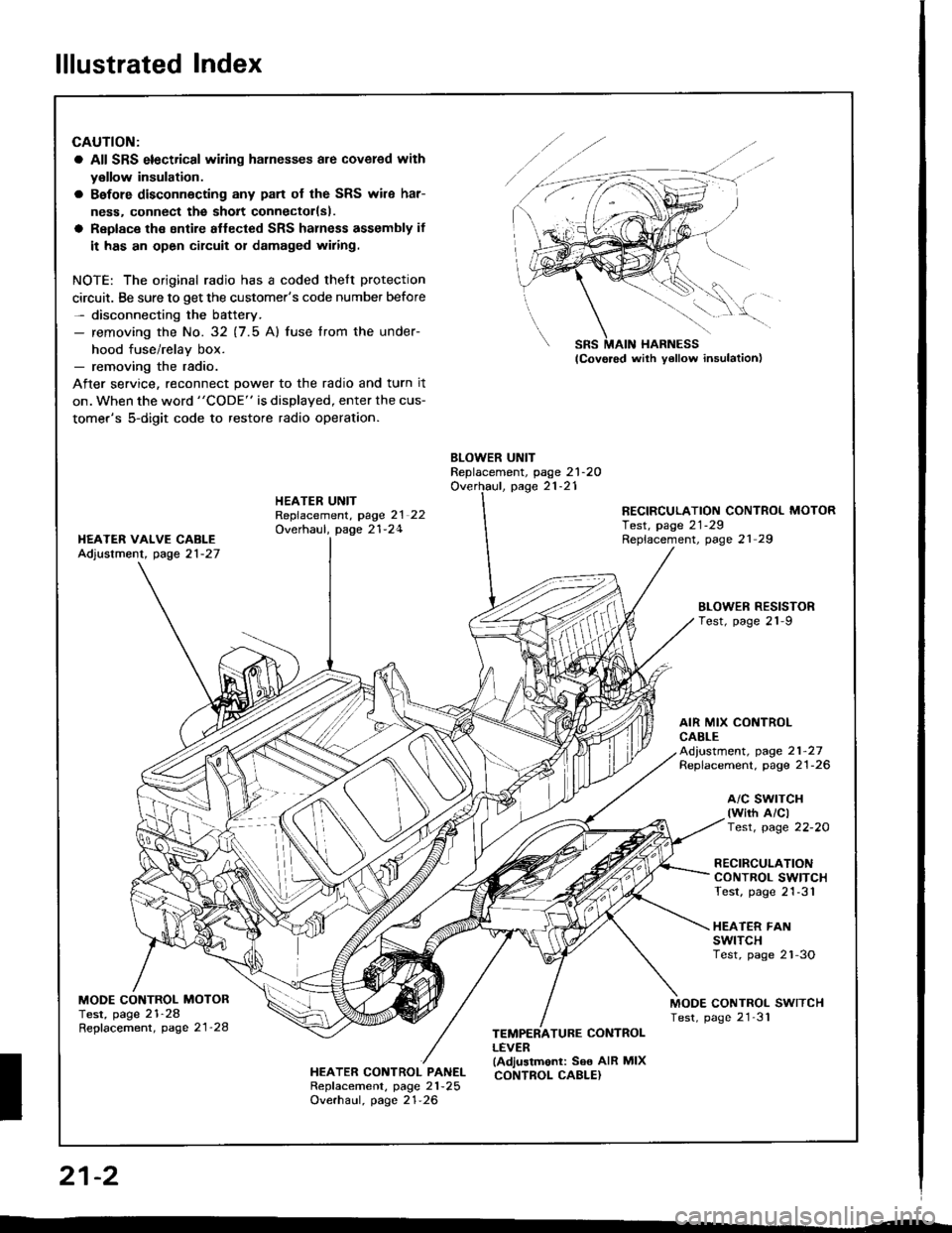
lllustrated Index
CAUTION:
a All SRS electrical wiling harnesses are covered with
y€llow insulation.
a Bafore disconnecting any pan of the SRS wile har-
ness. connect the sholt connectorlsl.
a Replace the sntire aflected SRS halness assembly if
it has an open circuit or damaged wiring.
NOTE: The original radio has a coded thelt protection
circuit. Be sure to get the customer's code number before- disconnecting the battery.- removing the No. 32 (7.5 Al fuse lrom the under-
hood fuse/relav box.- removing the radio.
After service, reconnect power to the radio and turn it
on. when the word "CODE" is displayed, enter the cus-
tomer's 5-digit code to restore radio operation.
BLOWER UNITReplacement, page 21-2OOverhaul, page 21-21HEATER UNITRepfacement, page 2l 22Overhaul, page 21-24
RECIRCULATION CONTROL MOTORTest, page 21-29Replacement, page 21 29I{EATER VAIVE CABLEAdjustment, page 21-27
BLOWEN RESISTORTest, page 21-9
AIR MIX CONTROLCABLEAd,ustment, page 21-27Replacement. page 21-26
a/c swrTcH(wirh A/clTest, page 22-20
RECIRCULATIONCONTROL SWITCHTest, page 21-31
HEATER FANswtTcHTest, page 2'l-3O
MODE CONTROL MOTORTest, page 21-28Repfacement, page 21'28
MODE CONTROL SWITCHTest, page 21'31
HEATER CONTROL PANELRepf acement, page 21 -25
Overhaul, page 21-26
TEMPERATURE CONTROLLEVER(Adjustmonl: See AIR MIXCONTROL CABLE}
SRS MAIN HARNESS
W,
21-2
I
Page 1059 of 1413
Heater Unit
Replacement
CAUTION:
a All SRS electrical witing hame$os are covoed wlth
yollow insulation.
a Before disconnecting any patt of tho SRS wito har-
neas, connect tha shott connoctol(s|.
a Roplaco th€ enlire sffacted SRS harnosr a$smbly if
it has an opon cilcult or dsmaged wiring.
NOTE: The original radio h8s a coded theft protection
circuit. Be sure to get the customer's code number betors
- disconnecting the bafterY.
- removing the No. 32 (7.5 A) fuse from th€ under-
hood tuse/relav box.- removing the radio
After service. teconnect power to the radio and turn it
on, when the word "CODE" is displayed, enter the cus-
tomer's 5-digit code to restore radio operation.
1. When the engine is cool, dtain the engine coolant
from the radiator (see section 1O).
@@ oo not lomove tho radiator cap whan
the ongine is hol; tha ongino coolant is undot
pressure and could a€voralY tcald you.
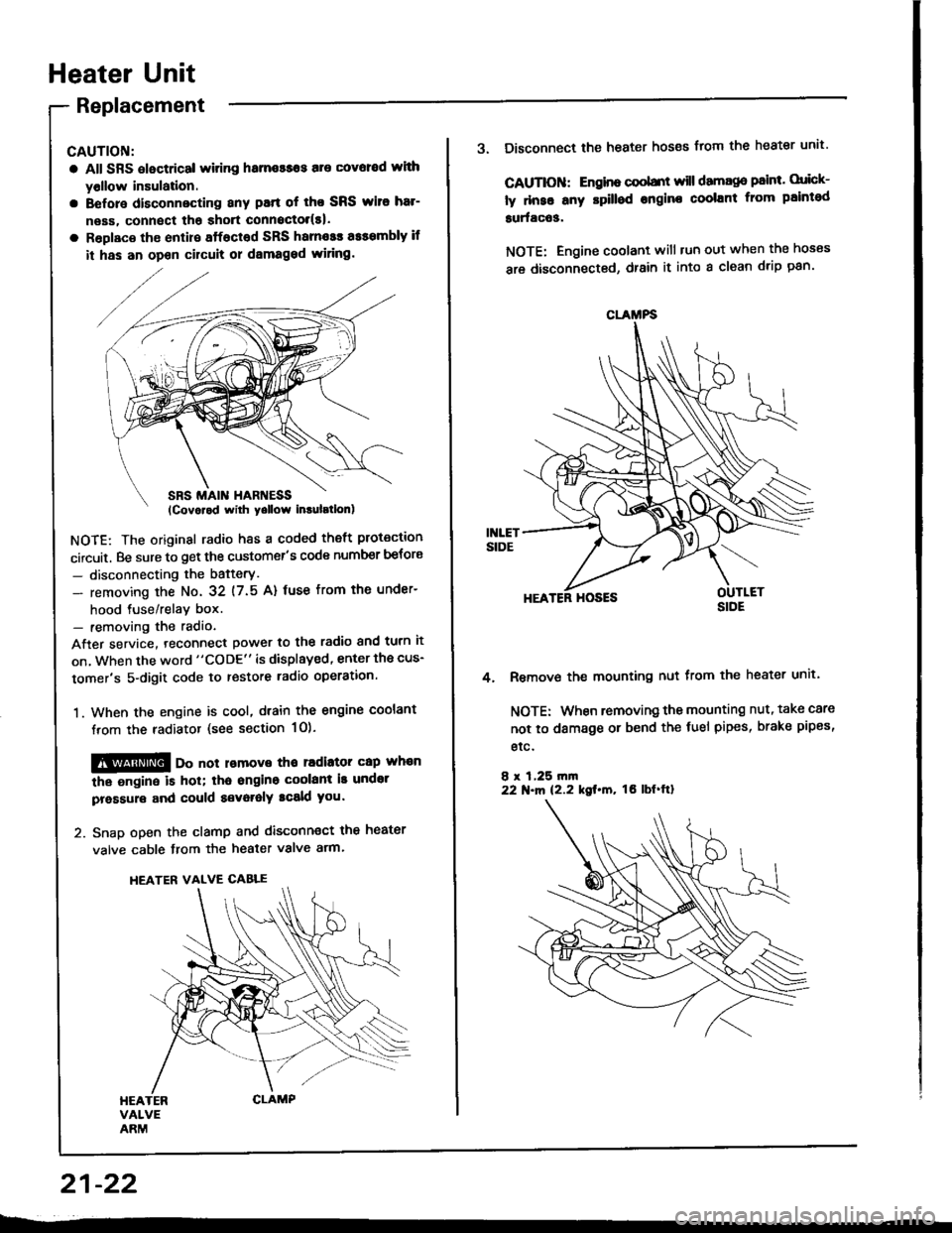
2. Snap open the clamp and disconnect the heater
valve cable from the heater valve arm.
HEATER VALVE CABLE
21-22
CLAMFS
3. Disconnect the heater hoses from the heater unit'
CAUTIOII: Engino coobnt will damago paint. orick-
ly dnse any rpilled engine coolant from paintod
surfac63.
NOTE: Engine coolant will tun out when the hoses
are disconnected, drain it into a clean drip pan'
HEATER HOSES
Remove the mounting nut from the heater unit.
NOTE: When removing the mounting nut, take care
not to damage or bend the fuel pipes, brake pipes,
etc.
8 r 1,25 rn|n22 N.m 12.2 kgt.m, tO lbf'ftl
4.
Page 1071 of 1413
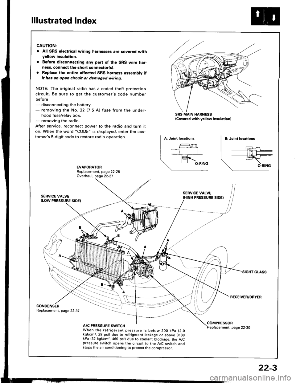
lllustrated Index
CAUTION:
. All SRS electrical wiring harnossos are cover€d withyellow insulation.
. B€fors disconnacting any part of the SRS wire har-ness, connsct the 3hort connsctor(s).. Replace the entirs affscted SRS harness assembly itit has an open circuit or damaged wiring.
NOTE; The original radio has a coded theft protection
circuit. Be sure to get the customer's code number
before- disconnecting the battery.- removing the No.32 (7.5 A) fuse from the under-
hood fuse/relay box.- removing the radio.
After service, reconnect Dower to the radio and turn it
on. When the word "CODE" is displayed, enter the cus-
tomer's 5-digit code to restore radio operation.
SRS MAIN HARNESSlcover€d with yellow insulationl
EVAPORATORReplacement, page 22-26Ovethaul. Oase 22.27
SERVICE VALVE(LOW PRESSURE SIDEI
SERVICE VALVEIHIGH PRESSURE SIDE)
RECEIVER/DRYER
CONDENSERReplacement, page 22,37
A/C PRESSURE SWITCHCOMPRESSORReplacement, page 22-30When the refrigerant pressure is below 200 kpa (2.0kqflcm,,28 psi) due to refrigerant leakage or above 3]OOkPa (32 kgf/cm,, 460 psi) due to coolant btockage, the A,/Cpressure switch opens the circuit to the A"/C switch andstops the air conditionang to protect the compressor.
22-3
Page 1109 of 1413
Troubleshooting
Tips and Precautions
Before Troubloshooting
a Check applicable fuses in the appropriate fuse/relay
DOX.
a Check the battery for damage, state of charge, and
clean and tight connections.a Check the alternator belt tension.
CAUTION:
a Do not quick-charg€ a battery unless the batteryground cabla has be€n disconnoctsd. oth€rwisoyou will damage the alternator diodss.a Do not att6mpt to crank the engine with the bat-tery ground cable loosely connectsd or you will se-vorsly damag€ tho widng.
a The original radio has a codod thatt plotection ci.-cuit. Be sul€ to got tho customor's code numbet
before- disconnecting th€ battery.- lomoving tho No. 32 (7.5 Al tuso f.om the
under-hood tuse/lelay box.- removing tho radio.
Aflor s€lvic€. reconn€ct powet to tho radio and
turn it on. Whon the word "CODE" is displayed,
€nt€l the customer'E s-digit codo to .astore ladio
operation.
Handling Connectors
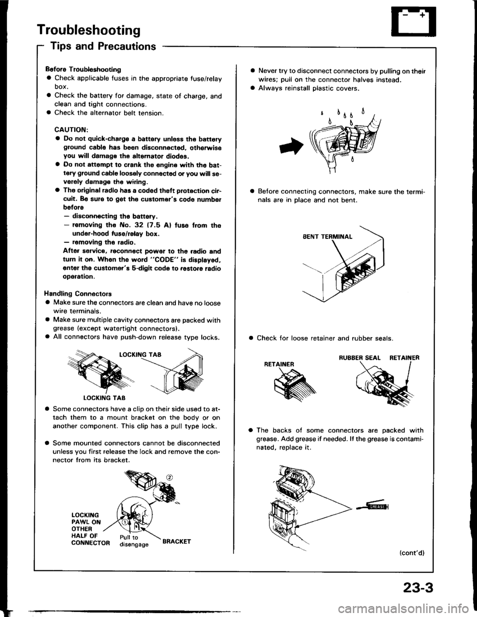
a Make sure the connectors are clean and have no loose
wire terminals.
a Make sure multiple cavity connectots are packed withgrease (except watertight connectors).a All connectors have push-down release type locks.
LOCKII{G TAA
LOCKING TAB
a Some connectors have a clio on their side used to at-
tach them to a mount bracket on the body or on
another component. This clip has a pull type lock.
a Some mounted connectors cannot be disconnected
unless you first release the lock and remove the con-
nector from its bracket.
LOCKINGPAWL ONOTHERHALF OFPull toorsengageCONNECTORBRACKET
23-3
a Never try to disconnect connectors by pulling on thei.
wires; pull on the connector halves instead.
a Always reinstall plastic covers.
Belore connecting connectors, make sure the lermi-
nals are in Dlace and not bent.
a Check tor loose retainer and rubber seals.
RETAINER
a The backs of some connectors are oacked with
grease. Add grease if needed. It the grease is contami-
nated, reDlace it.
(cont'd)
Page 1172 of 1413
Battery
a Battory tluid (6lectrolyt€l contains sulturic acid. lt may cauaa aevere burns iI it gots on your skin or in youl oyos.
Woar protoctivo clothing and I fac€ shield,- ll aloctrolyt6 gots on youl skin or clothos, rimo it off with wator immediately,- lf eloclrolyto g6ts in your oyos, tlush it out by splashing wat6r in youl eyes for at least 15 minutes; call a physiclan
immediately,
a A battery gives off hydrogon gas, lf ignit6d. tha hydrogsn will orploda and could crack tho baflory cas6 and splattor
acid on you. Koep spa*s. flames, and cigarottos away from the baftery.
a Overcharging will raiso ths tempelature ot th€ electrolyte. This may force electrolyte to splay out of the battery venta.
Follow lhe chargor manutacturer's instluctions and chargo tho battory at a prop61 rate.
NOTE: The original radio has a coded theft protection circuit. lt service to the car requires any of the lollowing, be sure
to get the customer's code number before- disconnecting the battery.- removing No. 32 (7.5 Al fuse from the under-hood fuse/relay box- removing the radio,
After service, reconnect power to the radio and turn it on. When the word "CODE" is displayed, enter the customer's
s-digir code to restore radio operation,
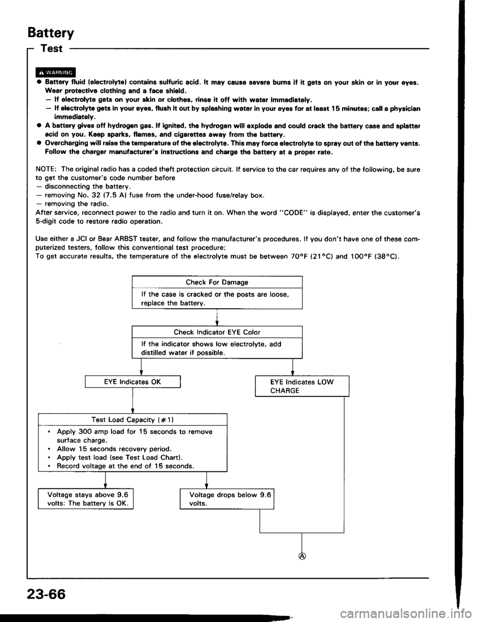
Use either a JCI or Bear ARBST tester, and follow the manufacturer's procedures. It you don'r have one of these com-puterized testers, follow this conventional test procedure:
To get accurate results, the temperature ot the electrolyte must be between TOoF l21ool and IOOoF {38oCl.
lf the case is cracked or the posts are loose,
replace the battery.
lf the indicator shows low electrolvte, add
distilled water it oossible.
Test Load Cspacity (# 1)
. Apply 3OO amp losd fo. 15 seconds to remove
surJace charge.. Allow 15 seconds recovery period.. Apply test load (see Test Load Chartl.. Record voltage at the end of 15 seconds.
Voltage stays above 9.6
volts: The batterv is OK.
23-66
Page 1177 of 1413
Electrical Switch Replacement
a All SRS €lectric8l wiring hamosses ar€ covorsd withyellow insulation,
a Befora disconnecting any pan of tho SRS wilo har-neas. connect the short connoctor(sl.a R6place the entire attect6d SFS harness assombly ifit has an opon circuit 01 damaged wiling.
NOTE: The original radio has a coded theft protection
circuit, Be sure to get the customer's code number before- disconnecting the battery.- removing the No. 32 (7.5 Al fuse from the under-hoodluse/relay box.- removang the radio.
After service, reconnect power to the radio and turn iton. When the word "CODE" is displayed, enter the cus-tomer's 5-digit code to restore radio ope.ation.
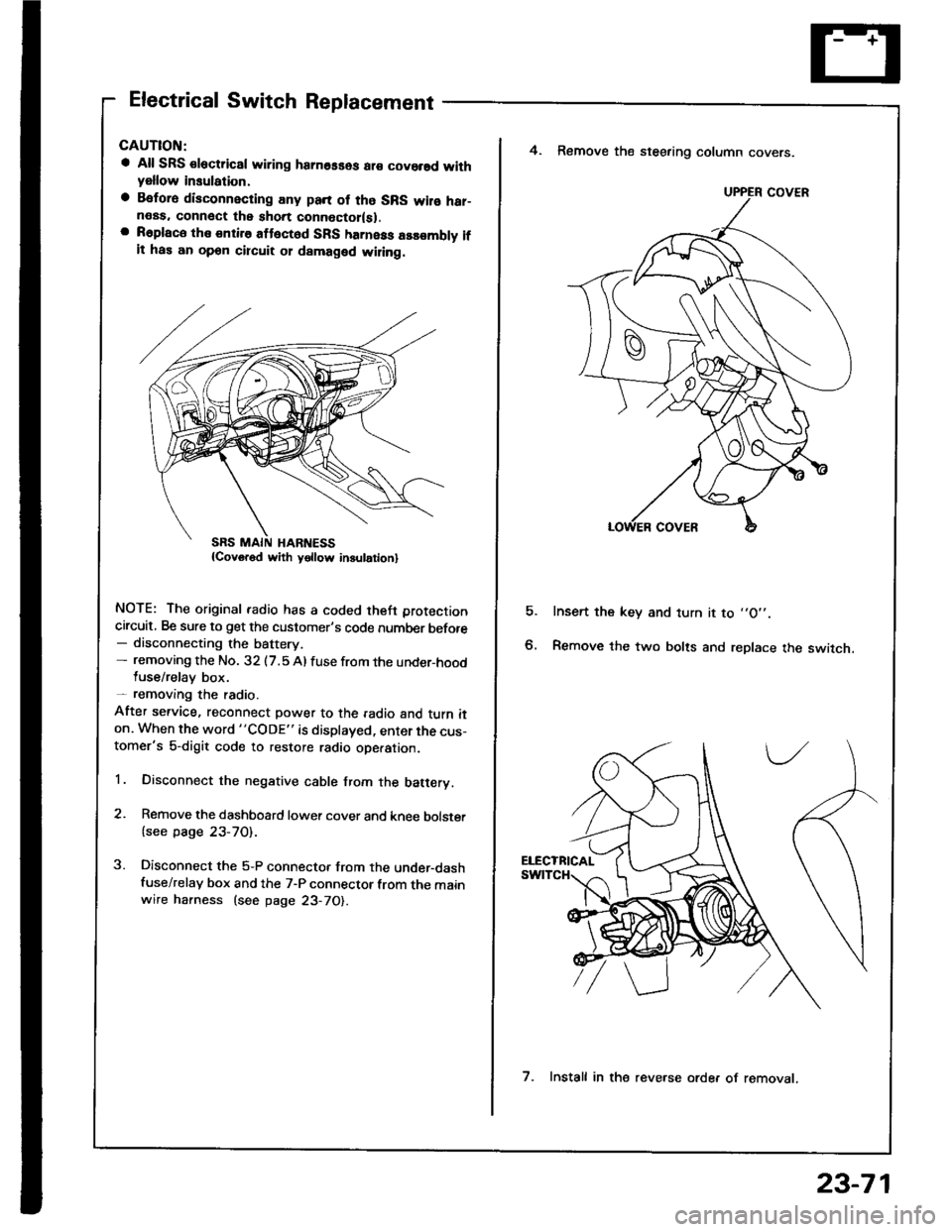
1. Disconnect the negative cable from the batery.
2. Remove the dashboard lower cover and knee bolster
{see page 23-70).
3. Disconnect the 5-P connector from the under-dashfuse/relay box and the 7-P connector from the mainwire harness (see page 23-70).
E
4. Remove the steering column covers.
Insert the key and turn it to ,,O',.
Remove the two bolts and replace the switch.
UPPER COVER
7. Install in the reve.se orde. of removat.
23-71
Page 1178 of 1413
lgnition Switch
Steering Lock Replacement
CAUTION:
a All SRS electrical wiring harnesses ale covsred with
yellow insulation.
a Belore disconnecting any parl ot the SRS wir€ hal-
ness, connecl the short connector{s).
a Replace the entire alfected SRS harness a$6mbly il
it has an open circuit or damaged wiring.
NOTE: The original radio has a coded thett protection
circuit. Be sure to get the customer's code number betore
- disconnecting the batterY.
- removing the No. 32 (7.5 A) fuse from the under-hood
fuse/relay box.- removing the radio.
After service, reconnect power to the radio and turn it
on. When the word "CODE" is displayed, enter the cus-
tomer's 5-digit code to restore radio operation.
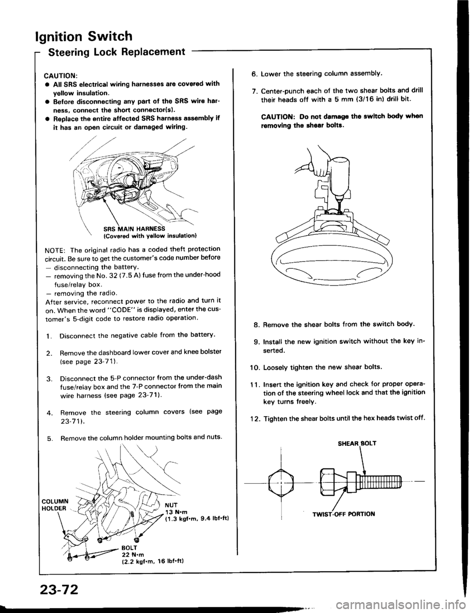
1. Disconnect the negative cable from the battery.
2. Remove the dashboald lower cover and knee bolster
(see page 23-7'l ).
3. Disconnect the 5-P connector from the under-dash
fuse/relay box and the 7-P connector trom the main
wire harness {see page 23-71).
4. Remove the steering column covers (see page
23-711.
5. Remove the column holder mounting bolts and nuts'
BOLT22 N.m
12.2 kgl'm.
NUT13 N.m(1.3 kgf.m, 9.4 lbl'ftl
23-72
16 tbt.ftl
6. Lower the steering column sssembly.
7. Center-Dunch each oJ the two shear bolts and drill
their heads off with a 5 mm {3/1 6 in) drill bit'
CAUTION: Do not dama96 tho switch body whon
r€movlng the shoar bol$.
Remove the shear bolts from the switch body.
Install the new ignition switch without the key in-
serted.
Loosely tighten the new shear bolts.
Insert the ignition key and check for proper opera-
tion of the steering wheel lock and that th€ ignition
key turns freely.
Tighten the shear bolts untilthe hex heads twist off.
8.
q
10.
11.
12.
Page 1186 of 1413
![HONDA INTEGRA 1994 4.G User Guide Starting
Startel
System
Overhaul
from clutch side.
-s@]
MOLYBDENUMDISULFIDE
CAUTION: Disconnecl th€ battery n€gative cable befole
lomoving the startet.
NOTE: The original radio has a coded theft p HONDA INTEGRA 1994 4.G User Guide Starting
Startel
System
Overhaul
from clutch side.
-s@]
MOLYBDENUMDISULFIDE
CAUTION: Disconnecl th€ battery n€gative cable befole
lomoving the startet.
NOTE: The original radio has a coded theft p](/img/13/6067/w960_6067-1185.png)
Starting
Startel
System
Overhaul
from clutch side.
-s@]
MOLYBDENUMDISULFIDE
CAUTION: Disconnecl th€ battery n€gative cable befole
lomoving the startet.
NOTE: The original radio has a coded theft protection
citcuit. Be sure to get the customer's code number before
- disconnecting the batterY.- removing the No.3 2 (7.5 A) fuse from the under-hood
fuse/relay box.- removing the tadio.
Atter service, reconnect power to the radio and turn at
on. When the word "CODE" is displayed, enter the cus-
tomer's 5-digit code to restore radio operation.
tr./.' BRUSH HOLDERTest, page 23-8'l
ERUSH
COVER
I
6
OVERRUNNING CLUTCH ASSEMBLYInspection, page 23_84
SOLENOIDPLUNGERInspection, page 23-85
BRUSH HOLOER
ARMATURE
STARTERSOLENOIDTest, page 23-78
PINION GEAR IDLER GEAR
Inspection, page 23-11
IDLER GEAR
I
@*
SOLENOID HOUSING
HARNESS BRACKET
STEEL BALL
install steel ball
lnspection and Test,page 23-82
ROLLER BEARINGSand CAGEPrevenl rollers trom being scattered and lost.
MOLYBDENUM DISULFIDE
_R1
MOLYADENUMDISULFIDE
23-80
ENO COVER
ARMATURE
GEAR HOUSING
Page 1210 of 1413
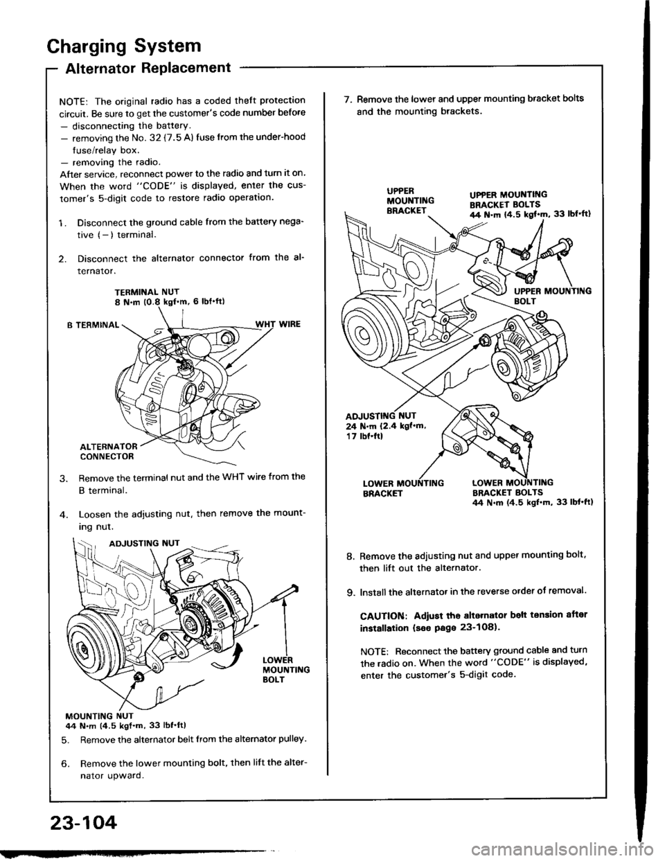
Charging System
Alternator Replacement
NOTE: The original radio has a coded theft protection
circuit. Be sure to get the customer's code number before
- disconnecting the battery.- removing the No. 32 {7.5 A) fuse from the under-hood
fuse/relay box.- removing the radio.
After service, reconnect powet to the radio and turn it on.
When the word "CODE" is displayed, enler the cus-
tomer's 5-digit code to restore radio operation.
1 . Disconnect the ground cable from the battery nega-
tive (- ) terminal.
2. Disconnect the alternator connector from the al-
rernaror.
TERMINAL NUT
B TERMINAL
ALTERNATORCONNECTOR
Remove the terminal nut and the WHT wire from the
B terminal.
Loosen the adjusting nut. then remove the mount-
Ing nul.
MOUNTING NUT44 N.m (4.5 kgt.m, 33 lbf'ftl
5. Remove the alternator belt from the alternator pulley.
6. Remove the lower mounting bolt, then lift the alter-
nator upward.
23-104
ADJUSTING NUT
w
UPPER MOUNTII{GBRACKET BOLTSil4 N.m {4.5 kgl'm, 33 lbl'ft}
24 N.m 12.4 kgf'm,'t 7 tbf.ftl
\ (^,-(\
\-/ I
7. Remove the lower and upper mounting bracket bolts
and the mounting brackets.
BRACKETBRACKET BOLTS44 N.m (4.5 ksl.m, 33 lbt'ft1
8. Remove the adiusting nut and upper mounting bolt,
then lift out the alternator.
9. lnstall the altetnator in the reverse order of removal.
CAUTION: Adiust tho alternalor belt tension aftor
installation (seo Page 23-1O81.
NOTE: Reconnect the battery ground cable and turn
the radio on. When the word "CODE" is displayed,
enter the customer's 5-digit code.