hatch trim HONDA INTEGRA 1994 4.G User Guide
[x] Cancel search | Manufacturer: HONDA, Model Year: 1994, Model line: INTEGRA, Model: HONDA INTEGRA 1994 4.GPages: 1413, PDF Size: 37.94 MB
Page 993 of 1413
Garpet
Replacement
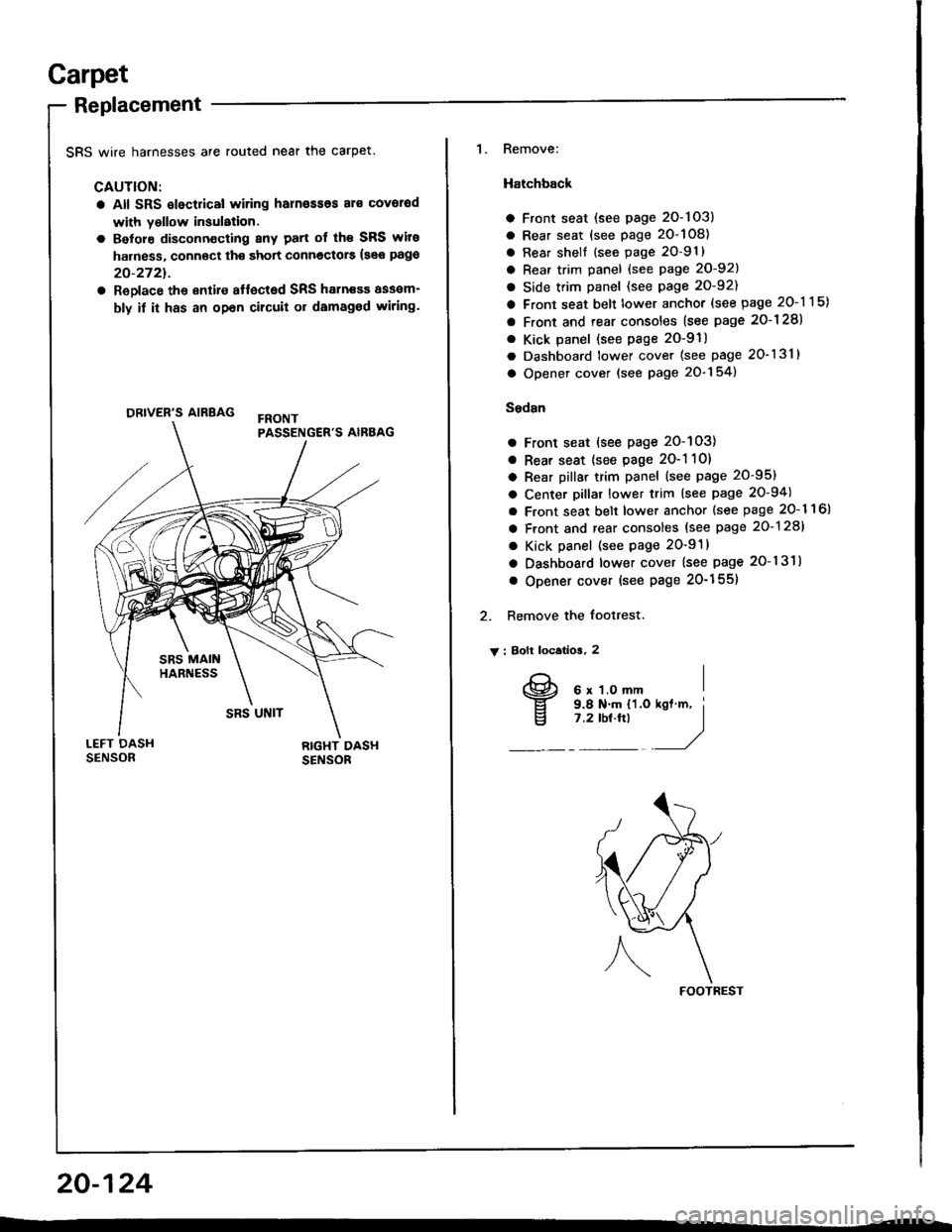
SRS wire harnesses are routed near the carpet.
CAUTION:
a All SRS slectrical wiring harn€ssos al€ covorod
with yollow insulation.
a Belore disconn€cting 8ny patt of th€ SRS wite
harness, connoct th€ short connectors {see pago
20-2721.
a ReDlace the €ntire affected SRS haln€sa assam-
bly if it has an opan cilcuit or damaged wiring.
ORIVER'S AIRBAG
1. Remove:
Hatchback
a Front seat (see page 2O-103)
a Rear seat (see page 20-108)
a Rear shell {see page 2O-91}
a Rear trim panel {see Page 20-921
a Side trim panel (see page 20-92)
a Front seat belt lower anchor (see page 20-115)
a Front and rear consoles (see page 2o-128)
. Kick panel (see page 2O-91)
a Dashboard lower cover (see page 20-131)
a Opener cover (see page 20-154)
Sedsn
a Front seat (see page 20-103)
a Rear seat {see page 2O-1 10)
a Rear pillar trim panel (see page 20-95)
a Center pillar lower trim (see page 20-94)
a Front seat belt lower anchor {see page 20- 1 1 6l
a Front and rear consoles (see page 20-128)
a Kick panel (see page 20-91)
a Dashboard lower cover (see page 20-131)
o Opener cover (see Page 20-155)
2. Remove the footrest.
V : Bolt locatios, 2
FOOTREST
20-124
I
v
6 x 1.O mm9.8 N.m {'l.o7 .2 tbt.ftl
Page 1010 of 1413
Rear Bumper Replacement
NOTE:
a An assjstant is helpful when femoving the rear bum-per and rear bumper beam.
a Take care not to scratch the rear bumper.
Hatchback
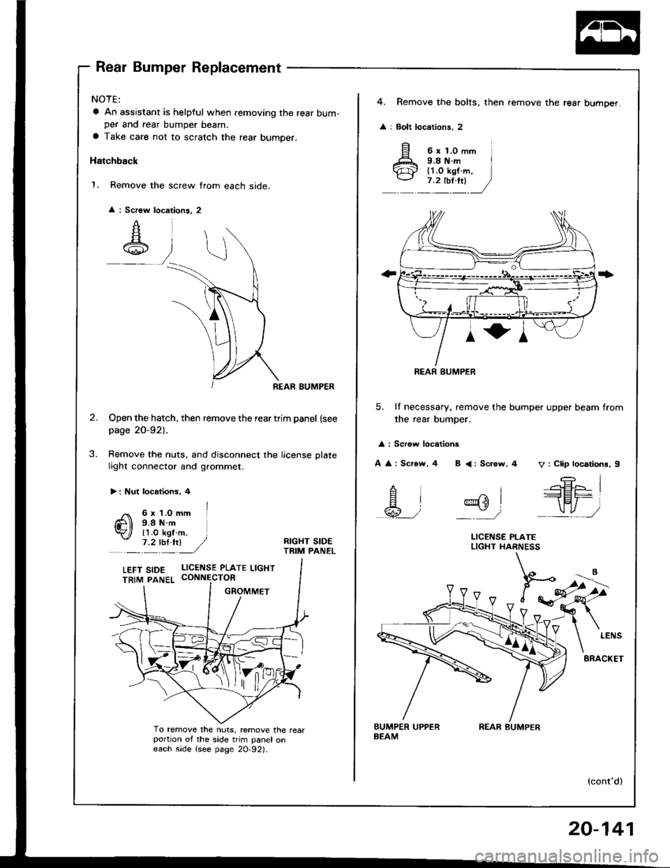
1. Remove the screw from each side.
REAR BUMPER
Open the hatch, then remove the rear trim panel (see
page 20-921-
Remove the nuts, and disconnect the license plate
light connector and grommet.
Scrow I
A
A\
:
J.
> : Nut locotions, 4
/ 6x1.Omm I
Q) i;L'i$-. l
_':'y:) ,/BIGHT SIDETRIM PANEL
To remove the nuts, remove the rearportion of the side trim panel oneach slde {see page 20-921.
LEFT S|DE L|CENSE PLATE LtcHT
4. Remove the bolts, then remove the rear bumper.
: Bolt locations, 2
5. lf necessary, remove the bumper upper beam from
the rear bumper.
: Screw locotions
A : Scr€w, 4 B <: Sc.ow, 4 V: Clip locations, I
REAR BUMPER
--E- I
.--r-Fl^ |--lEr-
_\"., J
^i
@sl
_'/
LICENSE PI-ATELIGHT HARNESS
(cont'd)
REAR BUMPER
20-141
Page 1015 of 1413
Hatch
Replacement
NOTE:
a An assistant is helpful when removing the hatch.
a Take care not to damage the hatch and body.
a Take care not to scratch the hatch side trims and hatch
tnm paner.
a Open the hatch.
a Remove the high mount brake light {see section 23).
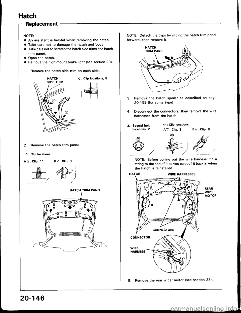
1. Remove the hatch side trim on each side.
HATCH< : Clip locations, 8
2. Remove the hatch trim panel.
A : Clip localions
AA : Clip, 11 BV : Clip, 3
W', dtri
::::/ _:_/
HATCH TRIM PANEL
NOTE: Detach the clips by sliding the hatch trim panel
forward, then remove it.
3. Remove the hatch spoiler as described on page
20-159 (for some type).
4. Disconnect the connectors, then remove the wire
harnesses from the hatch.
: Speclal boltlocetlons,2
V : Clip locations
Av : Clip, 3 BA: CliP, 6
4
t+Ltfrl
l'R@t
,/ L,/
A
@
l
)
NOTE: Before pulling out the wire harness, tre a
strinq to the end of it so you can pull it back in when
the hatch is reinstalled.
HATCI{WIRE I{ARNESSES
CONNECTORS
CONNECTOR
WIREHARNESS
20-146
5. Remove the rear wiper motor (see section 23).
Page 1016 of 1413
8.
o.
7.
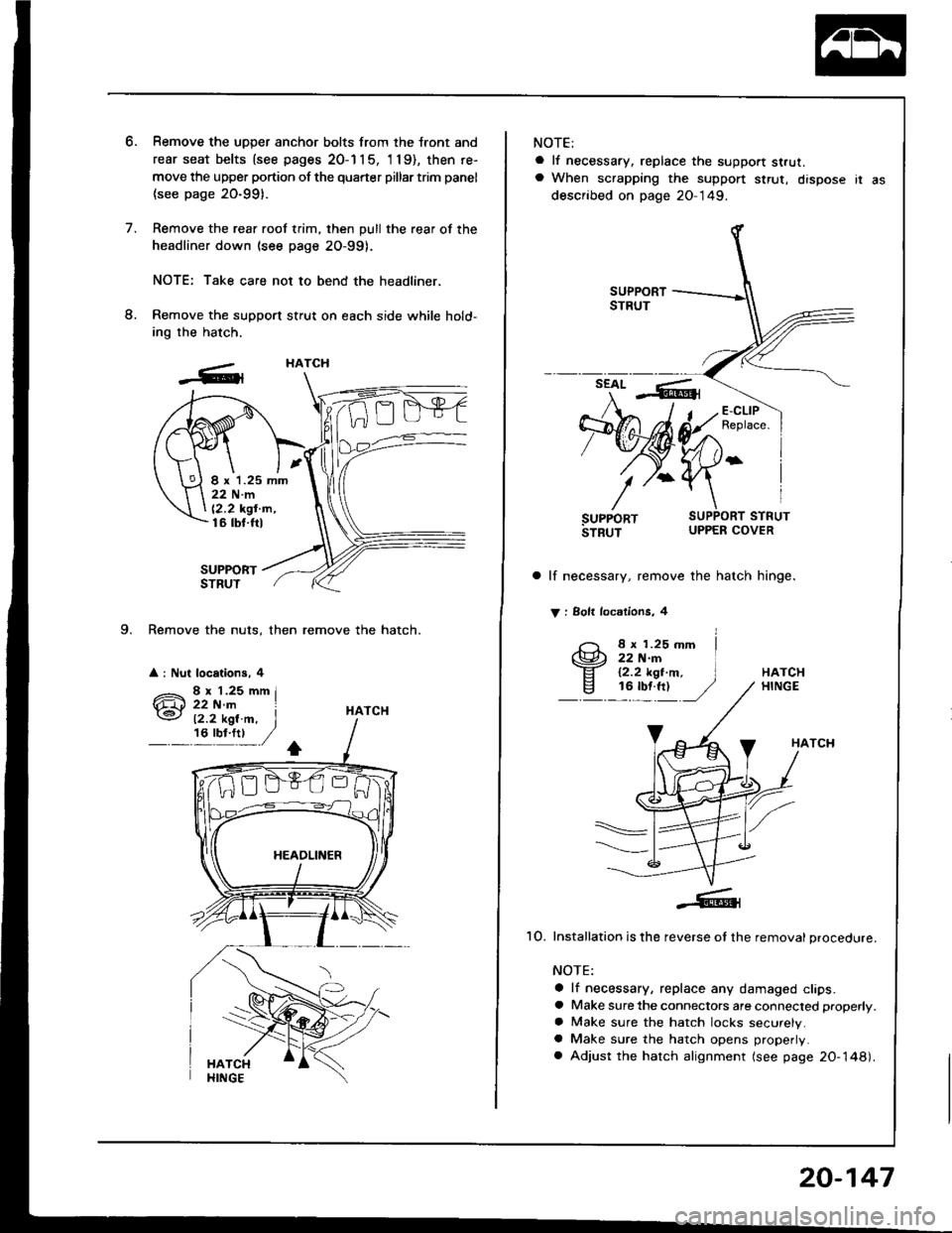
9. Remove the nuts, then remove the hatch.
a : Nut locations, 4
Remove the uDDer anchor bolts from the tront and
rear seat belts {see pages 20-1 1 5, 'l 19), then re-
move the upper portion of the quarter pillar trim panel
(see page 20-991.
Remove the rear roof trim, then pull the rear of the
headliner down (see page 2O-99).
NOTE: Take care not to bend the headliner,
Remove the support stfut on each side while hold-
ing the hatch.
SUPPORTSTRUT
HATCH
HATCH
I x 1.25 mm22Nm
12,2 kgt'm,16 tbt.ftl
12.2 kgl.m, I,6'y!:t ,/
NOTE:
a lf necessary, replace the support strut.a When scrapping the suppon $rut, dispose ir as
described on page 20-149.
a lf necessary, remove the hatch hinge.
V : Solt locdlions, 4
8 x 1.25 mm22 N.rn12.2 kgt.m,16 tbf.ft)HATCHHINGE
HATCH
1O. Installation is the reverse ot the removal procedure.
NOTE:
a lf necessary, replace any damaged clips.a Make sure the connectors are connected properly.
a Make sure the hatch locks securely.a Make sure the hatch opens properly.
a Adjust the hatch alignment (see page 20-148).
20-147
Page 1021 of 1413
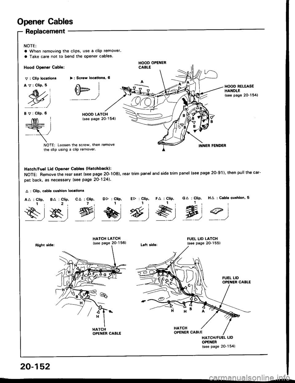
Opener Cables
NOTE:
a When removing the clips, use a clip remover.
a Take care not to bend the opener cables.
Replacement
Hood Opener Cable:
v : Clip location.
Av:CllP,5
M)
HOOD OPENERCABLE
> : Scrow locrtions, 6
Otr" I
:_ _)
HOOD RELEASEHAI{DLE(se€ page 20-1 54)
Bv:Clip.6HOOD LATCH(see page 20"154)E\I____lEt- L:=r
,/- -\-
NOTE: Loosen the screw, then remove
the clip using a clip remover.INNER FENDER
HA : C.bl6 cushlon, 5GA : Clip,
Wt
DD : Cllp, Etr : Cllp,1, I,
e&r @)9)
HATCH LATCH
lsee page 2O-1 56)Loft 3ido:
FUEL LID LATCH
lsse page 2O-155)
Hatch/Fuol Lid Oponer Cabls lHatchback):
NOTE: Remove the rear seat (see page 20-108), rear trim pan€l and side trim panel (see page 2O-91), then pull thecar-
Det back. as necessary lsee page 20-124).
A : Clip, csblo cushion location3
AA : Clip, 8A : Clip, CA : CliP,i r 2, 7,
s-,$, g,
FA : Cllp,
s,l
Right sids:
HATCHOPENER CABLE
HATCH/FUEL LID
OPENER{see page 2O-'l 54)
20-152
HATCH
Page 1022 of 1413
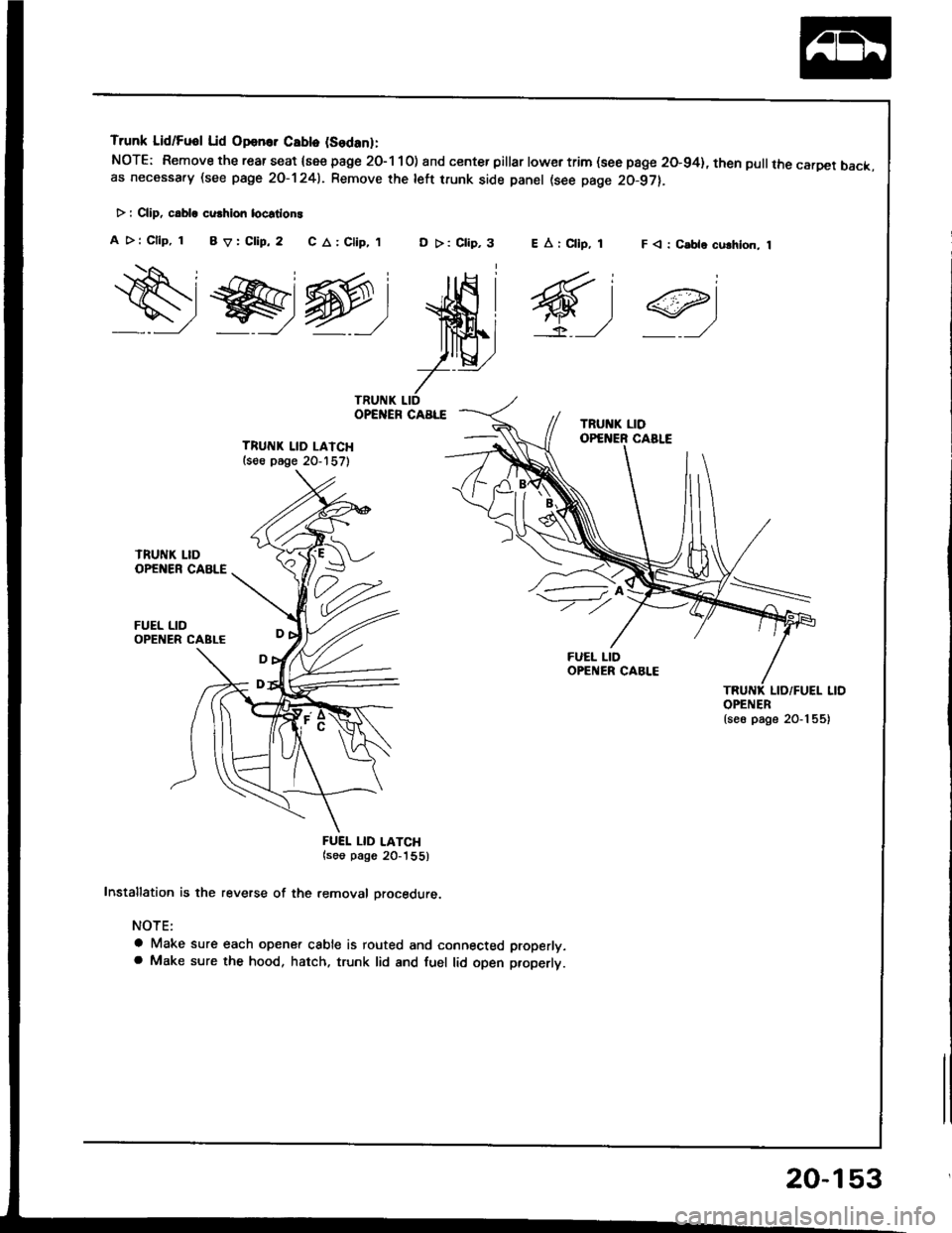
Trunk Lid/Fuol Lid Opan.. Cablo (Sodanl:
NOTE: Remove the rear seat {see page 2O-1 10) and center pillar lowertrim (see page 20-94}, then pullthe carDet back.as necessa.y (see page 2O-1241. Remove rhe left trunk side panel (see page 20-97).
> : CliD, c.bla cu.hion locstlon!
A >: Cllp, 1 BV:Clip,2 C A: Clip,,tD >: Clip,3F < : C.ble culhlon, 1
ws@:
ffi;
7--
TRUITIK LID LAICH(s€e p6ge 20-157)
FUEL LID
FUEI. LID LATCH(soo pago 20_'|55)
Installation is the reverse of the removal orocedure.
NOTE:
a Make sure each opener cable is routed and connected properly.a Make sure the hood, hatch. trunk lid and fuel lid open properlt.
EArCllp, 1
6,1
OPENER{se6 page 20-1 55)
20-153
Page 1024 of 1413
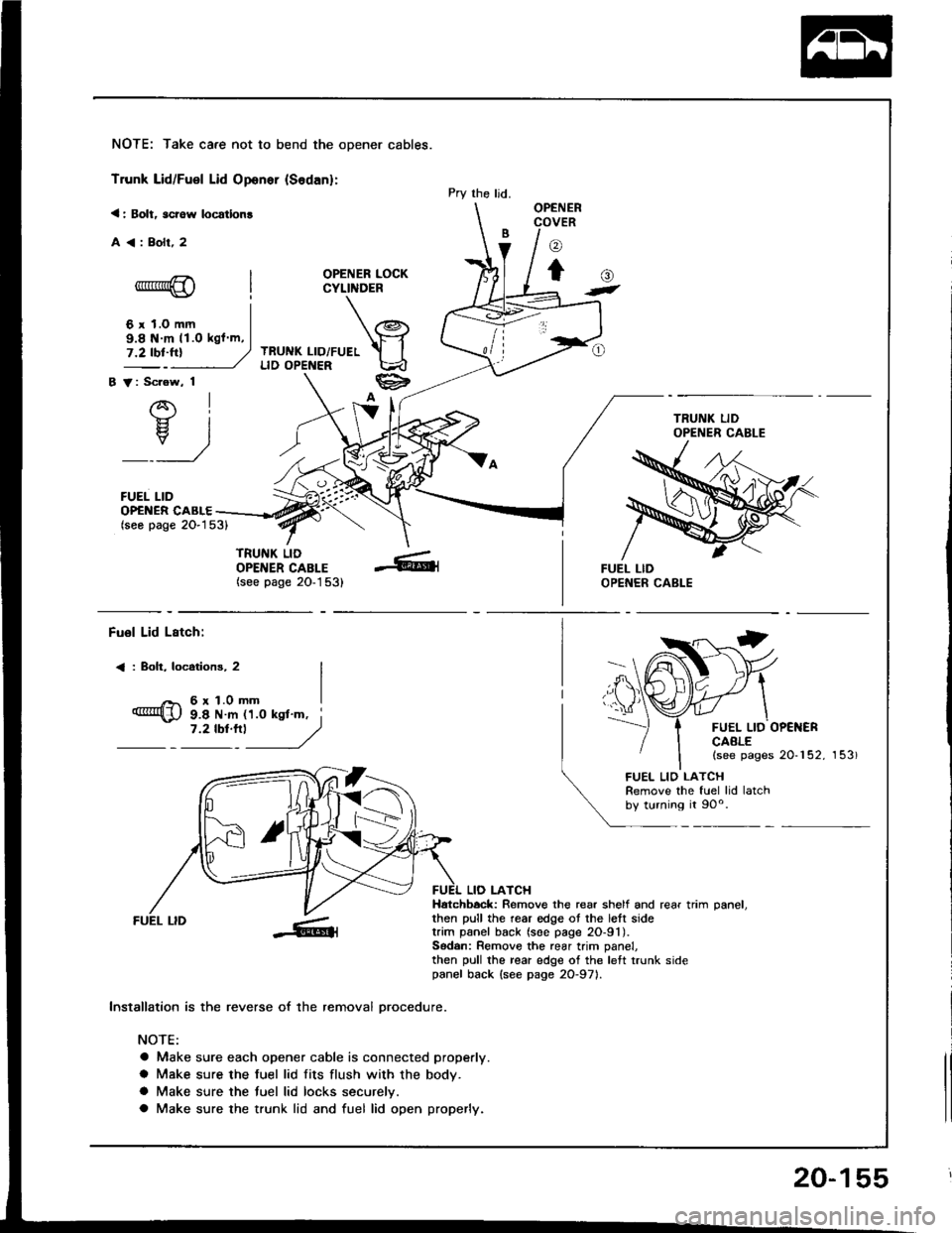
NOTE: Take care not to bend the opener cables.
Trunk Lid/Fuel Lid Oponer {Sodan}:
< : Bolt, scrow locatlon!
A<:Bolr,2
OPENER LOCKCYLINDER
TRUNK LID/FUELLID OPENER
B V: Scrow, 1
AI-}{- IH. I
_:_)
FUEL LID
Pry the ljd.OPENERCOVER
o
to-*rr*@
6 r 1.0 mm
()t
OP€NER CABLE(seo page 2O-153)
TRUNK LIDOPENER CABLE(see page 20-1 53)
9.8 N m 11.O kgl m,
Fuol Lid Lstch:
< : Boh, locotions, 2
6r1.0mm
FUEL LID OP€NERCAALE(see pages 20-152, 153)
9.8 N m 11.0 ksl'm, i7 '2 tbt'''l
------,//
FUEL LID
lnstallation is the reverse of the removal orocedure.
NOTE:
a Make sure each opener cable is connected properly.
a Make sure the fuel lid fits flush with the body.
a Make sure the tuel lid locks securelv.
a Make sure the trunk lid and fuel lid open properly.
LIO LATCHHatchbock: Remove the rear shelf and rear trim oanel.then pull the rear edge ot the lett sidetrim panel back (soe page 2O-91).Sodan: Remove the rear trim panel,then pull the rear edge of the left trunk sidepanel back {see page 2O-971.
FUEL LIO LATCHRemove the fuel lid latchby turning it 90o.
20-155
Page 1025 of 1413
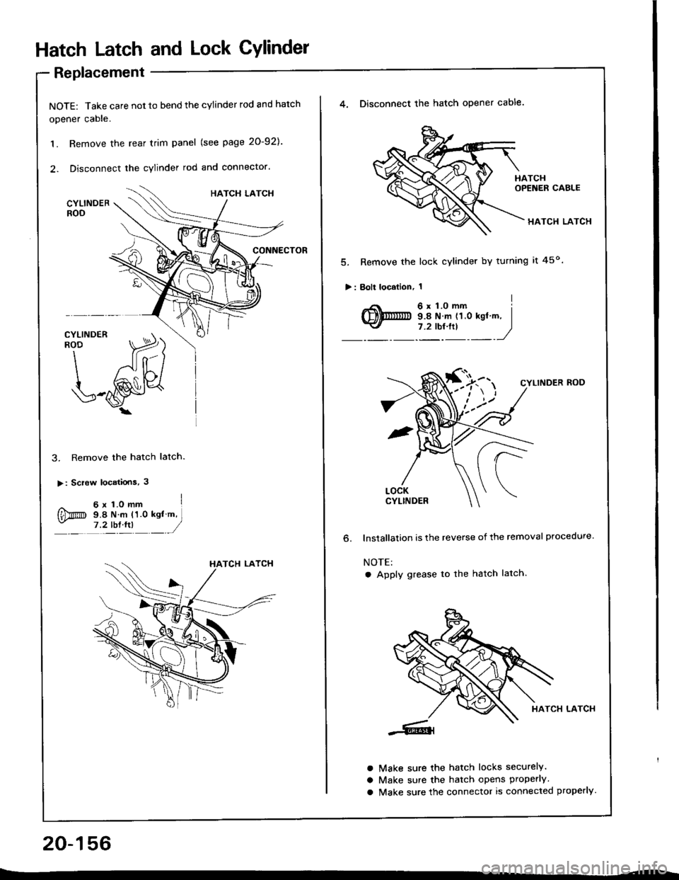
Hatch Latch and Lock CYlindet
Replacement
NOTE: Take care not 10 bend the cylinder rod and hatch
opener cable.
1. Remove the rear trim panel (see page 20-921.
2. Disconnect the cylinder rod and connector.
3. Remove the hatch latch.
>: Screw locatiois, 3
^ 6x1.omm I
{Dm s.e N m (1.0 ksl m,- ,?tb:tn __/
20-156
4. Disconnect the hatch opener cable.
HATCH LATCH
5. Remove the lock cylinder by turning it 45o
>: Bolt localion, 1
o.
CYLINDER ROD
lnstallalion is the reverse of the removal procedure.
NOTE:
a Apply grease to the hatch latch.
HATCH LATCH
Make sure the hatch locks securely.
Make sure the hatch opens properly.
Make sure the connector is connected properly.
a
a
a
Page 1028 of 1413
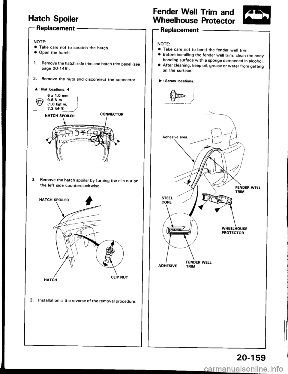
Hatch Spoiler
Replacement
a Take care not to scratch the hatch.a Open the hatch.
1. Remove the hatch side trim and hatch trim panel (seepage 2O-146).
2. Remove the nuts and disconnect the connector.
: Nut locations, 4
6 x 1.0 mm
Ch 9.8 N.m(J (1.0 ksl m, I__. 7,4b1!t ,/coI{t{EcroR
Remove the hatch spoiler by turning the clip nut onthe left side counterclockwise.
HATCH SPOILER
3. Installation is the reverse of the removal procedure.
Fender Well Trim and
Wheelhouse Protector
Replacement
a Take care not to bend the tender well trim.a Before installing the lender well trim, clean the bodvbonding surface with a sponge dampened in alcohol.a After cleaning, keep oil, g.ease or wafer lrom getlingon the surface.
> i Scr€w locations.
I
ADHESIVEFENDER WELLTRIM
20-159
Page 1031 of 1413
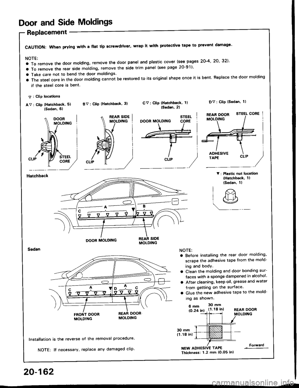
Door and Side Moldings
Replacement
CAUTION: When prying with 8 flal tip screwdriver, wrap it with protective tape to pr€vont damag€'
NOTE:
a To remove the doot moldlng, temove the door panel and plastic cover {see pages 2O-4' 2O' 32],'
a To remove the rear side molding, remove the side trim panel (see page 20-91)
a Take care not to bend the door moldings.
a The steel core in the door molding cann-ot be restored to its original shape once it is bent. Replace the door molding
if the steel core is bent.
V : Clip locations
av : cllp (Hatchb6ck, 5) BV: clip (Hatchback' 3)
V: Plastic nui locatlon(Hatchback, 1)(Sedan, 1)
CV: Cllp (Halchback, 1l{Sodan,2l
Dv: Clip lsodan, 1)
Hatchbsck
20-162
30 mm(1.18 inl
lnstallation is the reverse
NOTE: It necessary,
oJ the removal Procedure.
replace any damaged cliP.NEW ADHESIVE TAPE
Thicknoss: 1.2 mm lo.o5 inl
Forward
STEEL
CLIP
O'
lr>
r9
NOTE:
a BeJore instatling the rear door molding,
scrape the adhesive tape from the mold-
ing and body.
a Clean the motding and door bonding sur-
Jaces with a sponge dampened in alcohol'
a Atter cleaning, keep oil, grease and water
Jrom getting on the surface.
a Glue the new adhesive tape to the mold-
ing as shown.
6mm 30mm
ls 2f 61 . t.l.18 inlREAR DOORMOLDING