rocker HONDA INTEGRA 1994 4.G User Guide
[x] Cancel search | Manufacturer: HONDA, Model Year: 1994, Model line: INTEGRA, Model: HONDA INTEGRA 1994 4.GPages: 1413, PDF Size: 37.94 MB
Page 121 of 1413
Rocker Arms
Removal
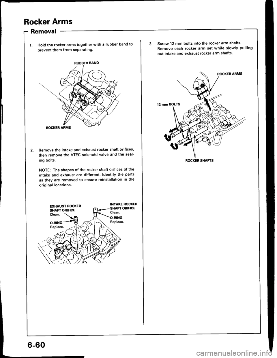
Hold the rocker arms together with a rubber band to
orevent them from seParating.
Remove the intake and exhaust rocker shaft orifices,
then remove the VTEC solenoid valve and the seal-
ing bolts.
NOTE: The shapes of the rocker shaft orifices of the
intake and exhaust are different. ldentify the parts
as they are removed to ensure reinstallation in the
original locations.
INTAKE ROCKERSHAFT OBIFICEClean.
O-RINGReplace.
RUBBER BAND
EXHAUST ROCKERSHAFT ORIFICEClean.
O.RINGReplace.
3. Screw 12 mm bolts into the rocker arm shafts.
Remove each rocker arm set while slowly pulling
out intake and exhaust rocker arm shafts.
ROCKER SHAFTS
Page 122 of 1413
Locations
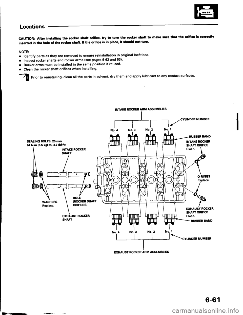
GAUTION: Aftcr in3tlllino th! roCk.r shrft o.ifice, trY to tum ihc tock r .hatt to makr luta thlt tho orifice ls corrccdY
in3artcd in the holc of tho lockor shrft. It the oritice b in placc' it should not turn'
NOTE:
o ldentify partsastheyare removed to ensure reinstallation in original locdtions'
. lnsoect rocker shafts and rocker arms (see pages 6-62 and 63)'
o Rocke. arms must be installed in the same position it reused'
. Clean the rocker shaft orifices when installing.
I erio, to ,einstalling, clesn all the parts in solvent, dry them and spply lubricant to any contact surfacos'
NTAKE BOCXER ARII,I ASSEi/IBUES
RUBBER BA D
INTAKE ROCXERsEALlMi BoLTS, 20 m|tr64 N.m 16.5 ksf.]n, 4.7 lbf.ftl
I
&
tu
SHAFTCl6an.
ry
ryHOII
o-nrM;sR6placo.
TROCIGR SHAFToRrFrcEsl
BOCXER
RUASER BA'{DSHAFT
-%
t
EXHAUST ROC(ER
EXHAUST B(rcKER ARM ASSEMBLIES
D*"'-,
6-61
Page 123 of 1413
Rocker Arms
lnspection
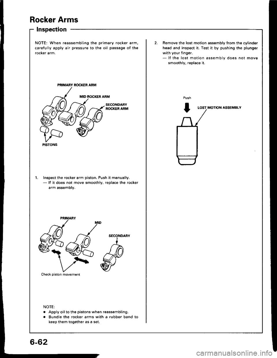
NOTE: When reassembling the
carefully apply air pressure to t
rocker arm.
Inspect the rocker arm piston.- lf it does not move smoot
arm assembly.
xva
V/\'Check piston movement
. Apply oilto the pistons whe
. Bundle the rocker arms wi
keep them together as a set.
PISTONS
) primary rocker arm,
the oil passage of the
Remove the lost motion assembly from the cylinder
head and inspect it. Test it by pushjng the plunger
with your finger.- lf the lost motion assembly does not move
smoothlv, reDlace it.
ROCKER ARMPush
t
SECONDARYLOST MOTION ASSEMBLY
ciston. Push it manually.
smoothly, replace the rocker
when reassembling.
s with a rubber band to
6-62
Page 124 of 1413
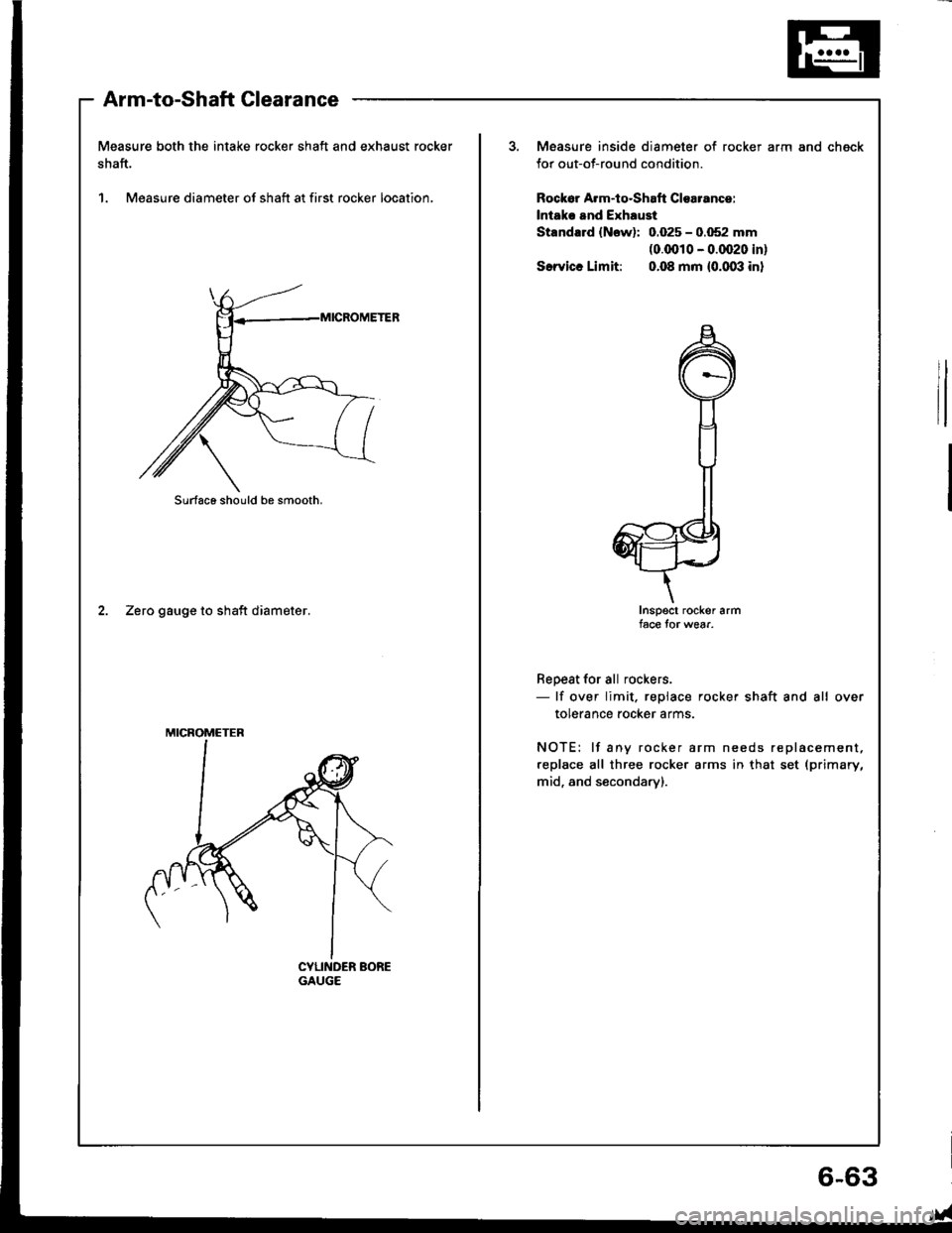
Measure both the intake rocker shaft and exhaust rocker
shaft.
1. Measure diameter of shaft at first rocker location,
Arm-to-Shaft Clearance
2. Zero gauge to shaft diameter.
Surfaco should be smooth.
MICROMETER
Measure inside diameter of rocker
for out-of-round condition.
Rock6r A.m-iq.Shaft Clearance:
lntak. and Exhaust
Standald (Now): 0.025 - 0.052 mm(0.0010 - 0.0020 in)
S.rvicc Limit: 0.08 mm {0.003 in}
arm and chgck
Inspect rocker armface tor wear.
Repest for all rockers.- lf over limit. replace rocker shaft and all over
tolerance rocker arms.
NOTE: lf any rocker arm needs replacement,
replace all three rocker arms in that set (primary,
mid, and secondary).
6,63
Page 125 of 1413
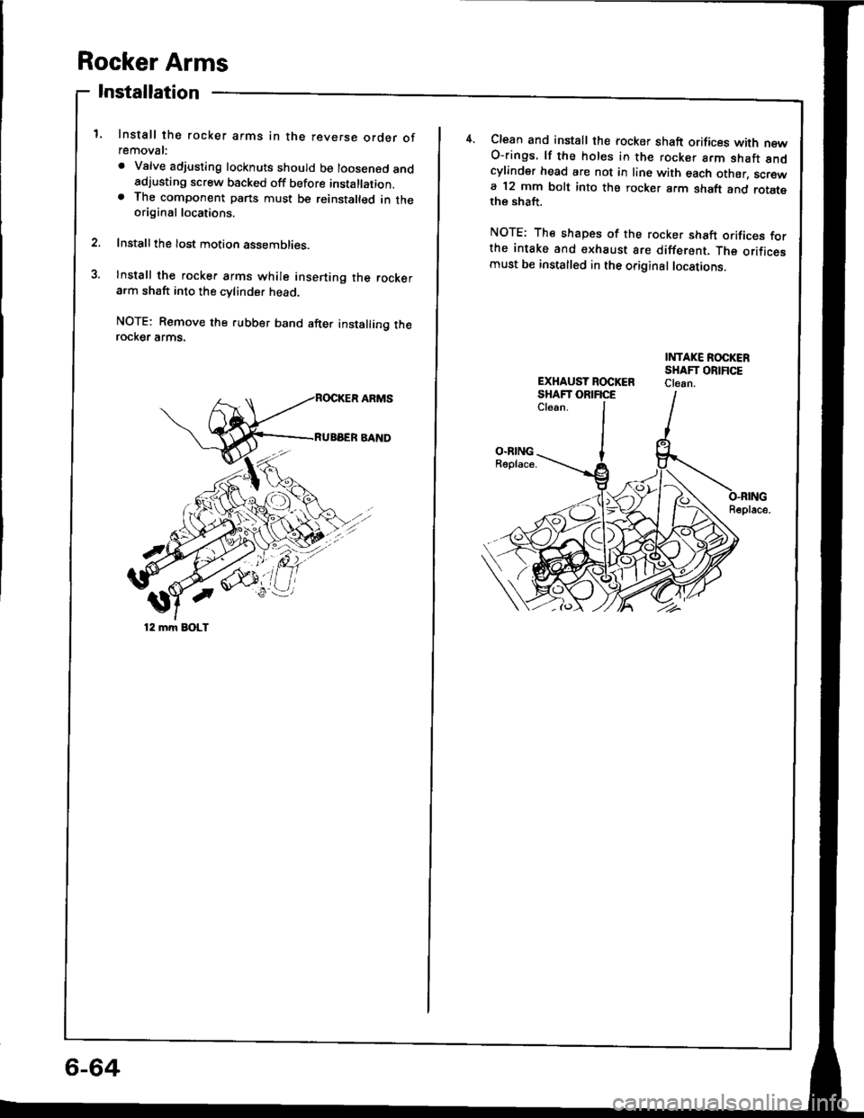
Rocker Arms
Installation
1. Install the rocker arms in the reverse order ofremoval:
. Valve adjusting locknuts should be loosened andadjusting screw backed off before installation.. The component parts must be reinstalted in theoriginal locations.
2. Installthe lost motion assemblies.
3. Install the rocker arms while insening the rockerarm shaft into the cvlinder head
NOTE: Remove the rubber band after installing therocKer arms.
'/'/
12 mm EOLT
4.Clean and install the rocker shaft orifices with newO-rings. lf the holes in the rocker arm shaft andcylinder head are not in line with each other, screwa 12 mm bolt into the rocker arm shaft and rotatethe shaft.
NOTE: The shapes of the rocker shaft orifices forthe intake and €xhaust are different. The orificesmust be installed in the original locations.
INTAKE ROCKERSHAFT ORIFICEClean.EXHAUST ROCKERSHAFT ORIFICECl6an.
O.RINGBeplace.
Beplace.
6-64
Page 126 of 1413
Camshafts
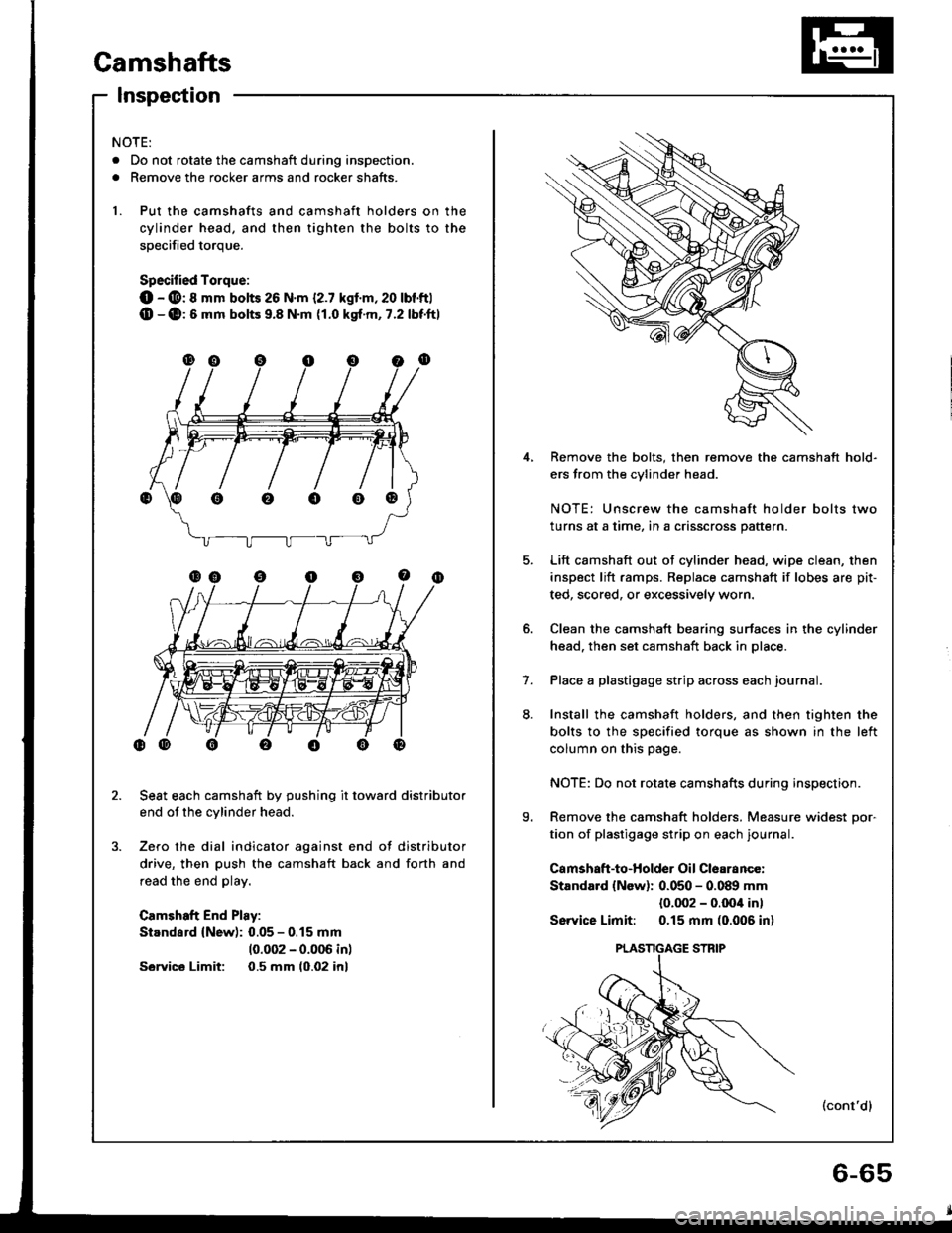
Inspection
4,
5.
9.
1.
Remove the bolts, then remove the camshaft hold-
ers from the cvlinder head.
NOTE: Unscrew the camshaft holder bolts two
turns at a time, in a crisscross pattern.
Lift camshaft out of cylinder head. wipe clean, then
inspect lift ramps. Replace camshaft if lobes are pit-
ted, scored, or excessively worn.
Clean the camshaft bearing surfaces in the cylinder
head. then set camshaft back in place.
Place a plastigage strip across each journal.
Install the camshaft holders, and then tighten the
bolts to the specified torque as shown in the left
column on this page.
NOTE: Do not rotate camshafts during inspection.
Remove the camshaft holders. Measure widest Dor-
tion of plastigage strip on each journal.
Camshaft-to-Holder Oil Clearance:
Standard {New): 0.050 - 0.089 mm
{0.002 - o.Ooil in)
Sswice Limit: 0.15 mm (0.006 in)
(cont'dl
NOTE:
. Do not rotate the camshaft during inspection.
. Remove the rocker arms and rocker shafts.
1. Put the camshafts and camshaft holders on the
cylinder head, and then tighten the bolts to the
soecified torque.
Specified Torque:
O - @: 8 mm bolts 26 N.m {2.7 kgl.m,20 lbt'ftl(D -(D:6 mm bolts 9.8 N.m {1.0 kgt.m, 7.2 lbf'ftl
Seat each camshaft by pushing it toward distributor
end of the cylinder head.
Zero the dial indicator against end of distributor
drive, then push the camshaft back and forth and
read the end play.
Camshaft End Play:
Standard (New): 0.05 - 0.15 mm
10.002 - 0.006 inl
Sawics Limit: 0.5 mm (0.02 inl
oooo@