torque HONDA INTEGRA 1994 4.G Workshop Manual
[x] Cancel search | Manufacturer: HONDA, Model Year: 1994, Model line: INTEGRA, Model: HONDA INTEGRA 1994 4.GPages: 1413, PDF Size: 37.94 MB
Page 30 of 1413
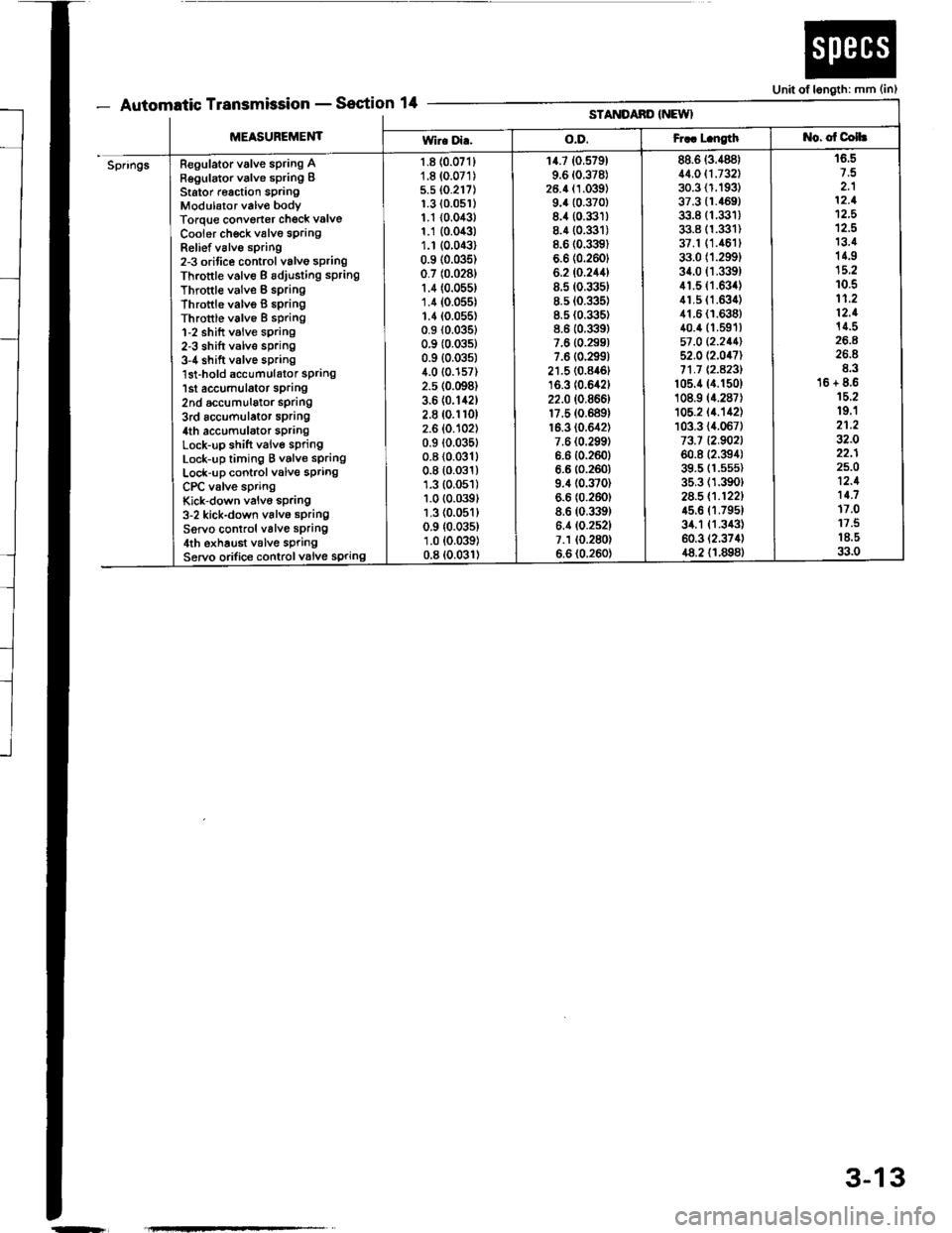
- Automatic TransmissionSection 14Unit of length: mm (in)
[t!'tttltttt tt -
MEASUREMENT
STANDAND INEWI
Wir. Di..o.D.Fr.. L.ngtht{o. of Colh
SpringsRegulator valve spring ARegulator valve spring IStator r€action springModulator valv€ bodyTorque convorter check valve
Cooier ch€ck valve sprangRelief v6lvo spring2-3 orifice control valvo springThrottle valve B adiusting sPring
Throttle valve B springThrottle valvo B 6pringThrottle valve I spring1-2 shift valve sprang2-3 shift valve spring3-4 shift valve spring'lst-hold accumulator spring1st accumulator sprang2nd accumulalor spdng3rd accumulator spring4th accumulator sPrangLock-up shift valve springLock-up timing B valve springLock-up control valve springCPC valve springKick-down valvo spring3-2 kick-down valvo springServo control valve spring4th exhaust v6lve springServo orifice controlvalve spring
1.8 {0.071}1.8 (0.071)
5.5 (0.217)
1.3 {0.0s1)1.1 {0.043}1.1 {0.043)1.r (0.043)
0.9 (0.035)
0.7 (0.0281
1.4 (0.055)
1.4 (0.055)
1.1(0.055)0.9 (0.0351
0.9 (0.0351
0.9 {0.035)4.0 {0.157)2.5 (0.098)
3.6 (0.142)
2.8 (0.1r0)
2.6 (0.102)
0.9 (0.035t
0.8 (0.0311
0.8 (0.031)
1.3 (0.051)
1.0 (0.039t
1.3 (0.051)
0.9 {0.035)1.0 (0.039)
0.8 (0.031)
14.7 (0.579)
9.6 (0.378)
26.4 (1.039)
9.4 {0.370}8.4 (0.331)
8.4 (0.3:]t)
8.6 (0.3l9)
6.6 (0.2601
6.2 (0.244)
8.5 (0.335)
8.5 (0.335)
8.5 (0.335)
8.6 (0.339)
7.6 (0.299)
7.6 (0.2991
21.5 (0.846t
16.3 (0.642)
22.0 (0.866)
17.5 (0.689)
16.3 (0.642)
7.6 {0.299)6.6 {0.260}6.6 (0.260)
9.4 (0.370)
6.6 (0.260)
8.6 (0.339)
6.4 (0.252)
7.1 (0.280)
6.6 (0.260)
88.6 (3.488)
11.011.732130.3 (1.193)
37.3 {1.469)33.8 (1.331)
33.8 (1.331)
37.1 (1.461t
33.0 (1.299)
34.0 fi.339)41.5 (1.634)
41.5 (1.63i1)
41.6 {1.638}40.4 (1.591)
57 ,0 12.211152.0 (2.047)
71.1 Q.A23l't05.4 (4.150)
108.9 (4.287)
105.2 (4.'�142)
103.3 {4.067)73.7 12.902160.8 (2.394)
39.5 (1.5s5)
35.3 (1.390)
2a.5 (.1221
45.6 (1.795t
34.1 {1.343)60.3 (2.374)
48.2 {1.898}
16.5
2.112.1't2,5
12.513.414.9
10.511.212.114.5
26.8E.316 + 8.615.219.'l21.232.022.125.O12.111.717.011.518.533.0
-r
3-13
Page 31 of 1413
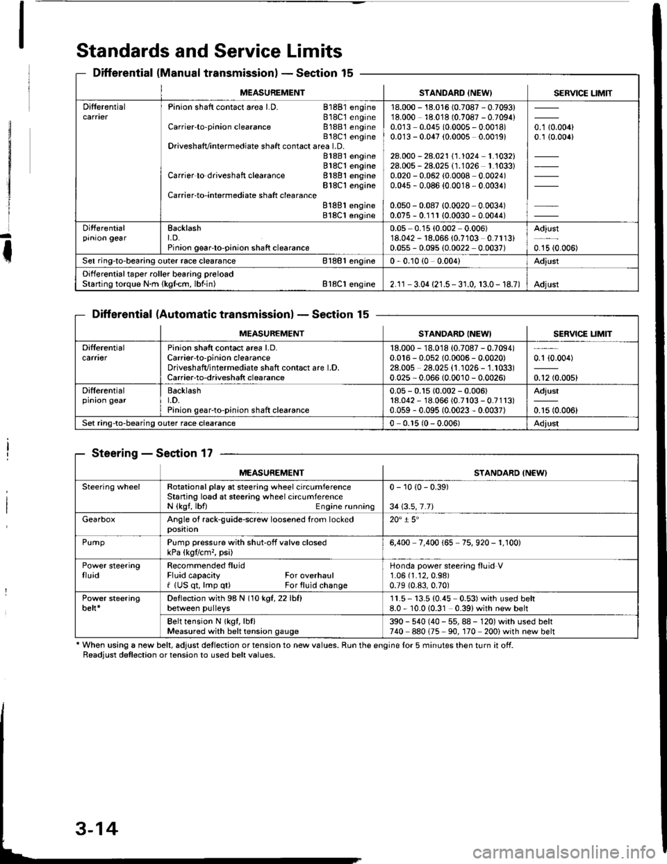
Standards and Service Limits
Differential (Manual transmissionlSection 15
Differential (Automatic transmissionlSection 15
Steering - Section 17
' When using a new belt, adjust detlection or tension to new values. Run the engine lor 5 minutes then turn it off.Readiust detlection or tension to used belt values.
M€ASUREMENTSTANDARD INEW) SERVICE LIMIT
DifferentialPinion shaft contact area LD. 81881 engine818C1 engineCarrier'to-pinion clearance 81881 engineB18C t engineDriveshafvintermediate shaft contact area LD.81881 engine818C1 engineCarrier to driveshaft clearance 81881 engineBlSC'l engineCarrier-to-intermediate shatt clearanceB188l engine818C1 engine
18.000 - 18.016 (0.7087 - 0.7093)18.000 18.018 (0.7087 - 0.7094)0.0r3 0.045 (0.0005 - 0.0018)0.0'13 - 0.047 (0.0005 0.0019)
28.000 - 28.021 \1.1024-1.1032128.005 - 28.025 (1.1026 1.'1033)0.020 - 0.062 (0.0008 0.0024)0.045 , 0.086 {0.0018 - 0.0034)
0.050 - 0.087 (0.0020 0.0034)0.075 - 0.111 (0.0030 - 0.0044)
o. t aron,0.1 {0.006}
Differentialprnron gearEacklasht. D.Pinion geaFto-pinion shaft clearance
0.05 0.15 (0.002 0.006)'18.042 - 18.066 (0.7103 0.7113)0.055 - 0.095 (0.0022 0.0037)
Adjust
0.15 {0.006)
Sel ring-to-bearing outer race clearance 81881 engin€0 - 0.10 (0 0.004)Adjust
Differential taper roller bearing preloadStarting torque N.m {kgfcm, lbf.in) Bl8Cl engine2.1r - 3.04 {21.5 - 3 r.0, 13.0- 18.7)Adjust
MEASUREMENTSTANDARO INEWISERVICE LIM]T
Difterentialcarfl€rPinion shatt contact area l.D.Carrier-to-oinion clearanceDriveshafvintermediate shaft contact are l.D.Carrier-to-driveshatt clearance
18.000 - 18.018 {0.7087 - 0.7094)0.016 - 0.052 {0.0006 - 0.0020)28.00s 28.025 {1.1026 - 1.1033)0.025 - 0.066 (0.0010 - 0.0026)
0.1 {0.004)
0.12 (0.005)
Differentialprnron gearBacklasht.D.Pinion gear-to-pinion shaft clearance
0.05 - 0.15 (0.002 - 0.006)18.042 - 18.066 (0.7r03 - 0.7113)0.059 - 0.095 (0.0023 - 0.0037)
Adjust
0.15 (0.006)
Set ring-to-bearing outer race clearance0 - 0.r5 (0 - 0.006)Adjust
MEASUREMENTSTANDARD INEWI
Steering wheelRotational play at steering wheel circumferenceStaning losd at steering wheel circumferenceN {kgf, lbfl Engine running
0 - 10 {0 - 0.39)
34 \3.5,7.71
GearboxAngle of rack-guide-screw loosened from lockedposition20" i 5'
PurnpPump pressure with shut-off valve closedkPa (kgtlcm,, psi)6,400 7.400 165 75. 920 - 1. r00)
Power steeringtluidRecommended fluidFluid capacity For overhaulf (US qt, lmp q0 For fluid change
Honda power steering fluid V1.06 (1.12,0.98)
0.79 (0.83,0.70)
Power steeringbelt*Deflection with 98 N (1okgt,22lhfl
between pulleys11.5- 13.5 (0.45 0.53)with used belt8.0 - 10.010.31 0.39)with new belt
Belt tension N lkgf, lbl)Measured with belt tension gauge390 - 540 (40 - 55, 88 - 120) with used belt740 880175 90. 170 200) with new belt
Page 46 of 1413
Engine Removal/lnstallation
Special Tools ........ .".....5-2
Engine Removal/lnstallation ..."........ 5-3
Mount/Bracket Torque ..' 5-16
Page 61 of 1413
il
I
I
I
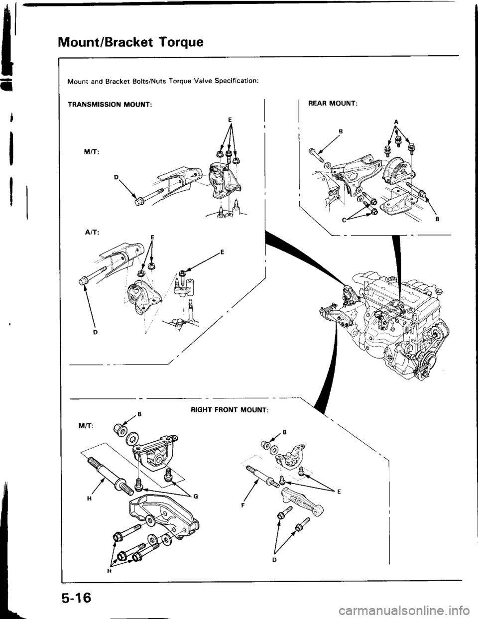
Mount/Bracket Torque
Mount and Bracket Eolts/Nuts Torque Valve Specification:
TRANSMISSION MOUNT:
Page 63 of 1413
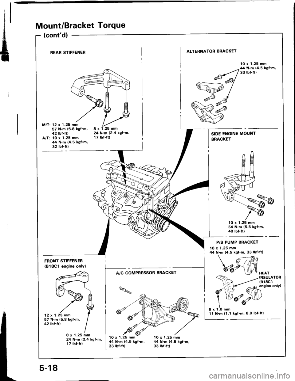
Mount/Bracket Torque
(cont'd)
REAR STIFFENER
M/T: 12 x '1.25 mm57 N.m 15.8 kgf'm,42 rbf.ft)A/T: 10 x 1.25 mm/14 N.m {4.5 kgf.m,32 tbt.ftl
ALTERNATOR BRACKET
10 x 1.25 mm
8x1.25mm24 N.m 12.4 kgf'm,
17 tbt.ftt
lO r 1.25 mm54 N'm (5.5 kgl.m,40 tbf.ft)
FRONT STIFFENER
(B18Cl engin€ onlyl
'12 x 1 .25 mm
f--^,c*;"*".*-
t-*i;
lq
I -4M
- Ghinein"onvt
ddv
HEATINSULATOR(818C1
P/S PUMP BRACKET
10 x 1.25 mm44 N.m (4.5 kgf'm, 33 lbf'ft|
57 N.m 15.8 kgt.m,42 tbf.fr)
8 x 1.25 mm24 N.m (2.4 kgf.m,17 tbf.ft)
10 x 1.25 mm 10 x 1.25 mnl44 N.m {4.5 kgf.m, 44 N.m (4.5 kgf.m,33 rbr.ftt 33 rbr.tt)
SIDE ENGINE MOUNT
BRACKET
5-18
'11 N.m (1.1 kgl'm,8 O lbf'tt)
Page 66 of 1413
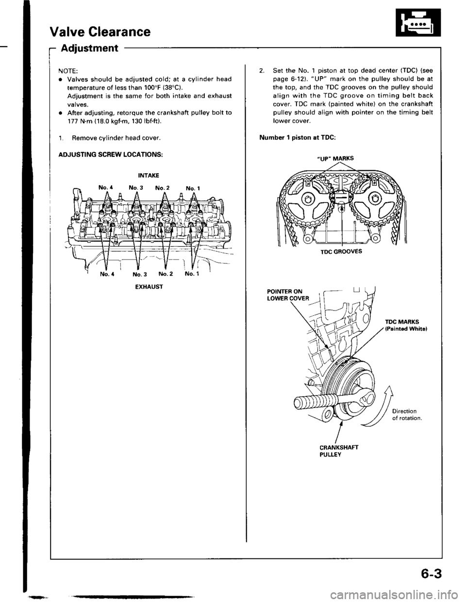
6-3
Valve Clearance
Adjustment
NOTE:
. Valves should be adjusted cold; at a cylinder head
temperature of less than 100'F (38"C).
Adjustment is the same for both intake and exhaust
valves.
. After adjusting, retorque the crankshaft pulley bolt to
177 N.m (18.0 kgim, 130 lbf.ft).
1. Remove cylinder head cover.
ADJUSTING SCREW LOCATIONS:
2. Set the No. 1 piston at top dead center (TDC) (see
page 6-12). "UP" mark on the pulley should be at
the top, and the TDC grooves on the pulley should
align with the TDC groove on timing belt back
cover. TDC mark (painted white) on the crankshaft
pulley should align with pointer on the timing belt
tower cover.
Number 1 Diston at TDC:
INTAKE
EXHAUST
TDC MARKSlPeinted whitel
CRANKSHAFTPULLEY
"UP" MARKS
TDC GROOVES
Page 71 of 1413
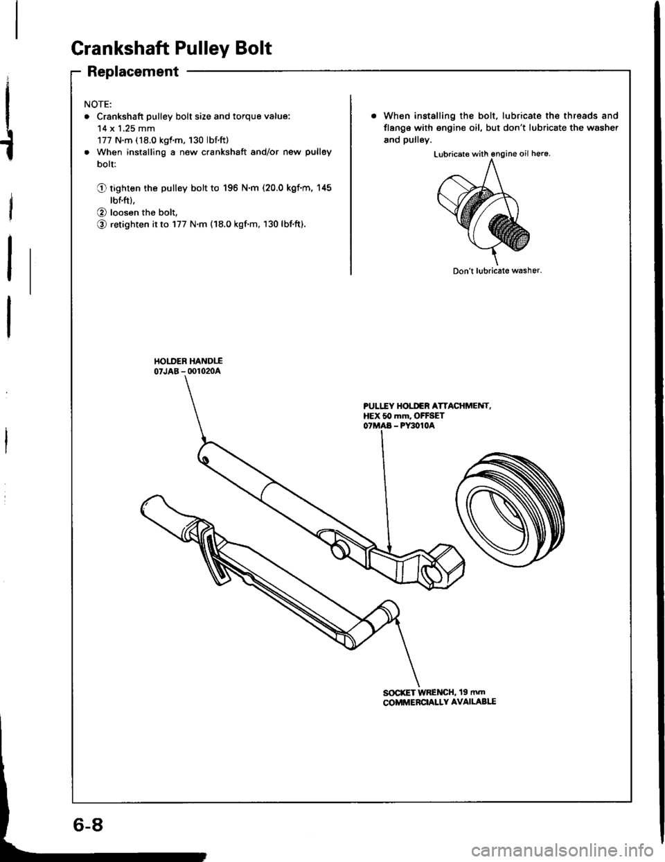
Crankshaft Pulley Bolt
Replacement
I
t
NOTE:
. Crankshaft pulley bolt size and torque value:
14 x 1.25 mm
177 N.m (18.0 kgt.m. 130 lbf.ft)
. When installing a new crankshaft and/or new pulley
bolt:
Q tiglten the pulley bolt to 196 N.m (20.0 kgf.m, 145
tbnft).
O loosen the bolt,
O retighten it to 177 N.m (18.0 kgf'm. 130 lbf.ft).
When installing the bolt, lubricate the threads and
flang€ with engin€ oil, but don't lubricate the washe.
and pulley.
Don't lubricat€ washer.
HOI-DER HANDIIo'JAB -oo1020A
PULI.TY HOI.I'€R ATTACHi'ENT,HEX 50 mm. OFFSET- PY3010A
SOCrET WRENCH, 19 mm
COMMERCI,ALLY AVAILABI.I
Page 72 of 1413
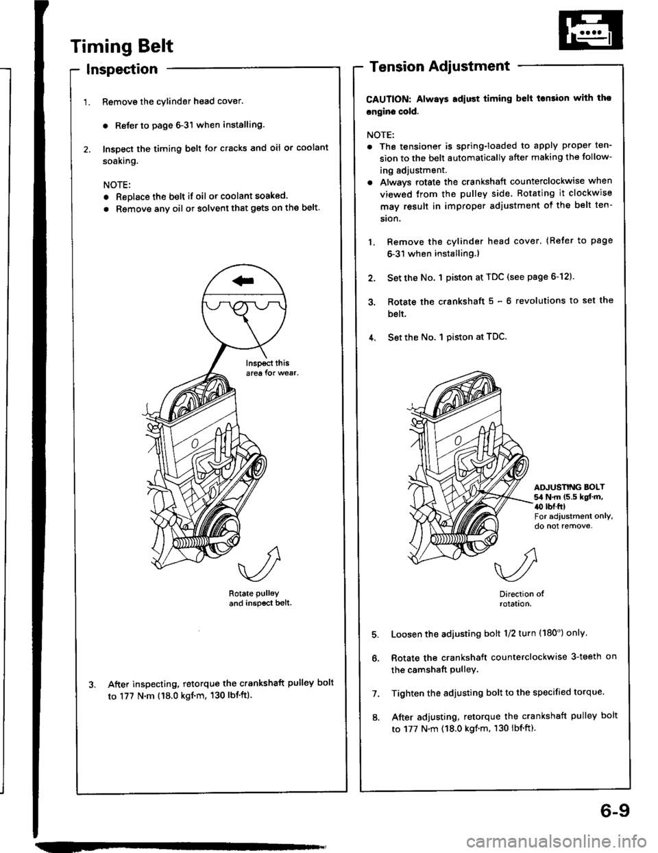
Timing Belt
Inspection
Remove the cylinder head cover.
. Reler to page 6-3'l when installing.
Inspect the timing belt for cracks and oil or coolant
soaking.
NOTE:
. Replace the belt if oil or coolant soaked.
. Rsmove any oil or solvent that gets on the belt.
Rotate pulley
and inspscr bell.
After inspecting, retorque the crankshaft pulley bolt
to 177 N'm ('18.0 kgf'm, 130 lbt'ft).
Tension Adjustment
CAUTION: Always Ediust timing belt tonsion with tho
cngin. cold.
NOTE:
. The tensionet is spring-loaded to apply proper ten-
sion to the belt automaticallv after making the follow-
ing adjustment.
. Always rotate the crankshaft counterclockwise when
viewed trom the pulley side Rotating it clockwise
may result in improper adjustment ot the belt ten-
sion.
Remove the cylinder head cover. (Refer to page
6-31 when installing.)
Set the No. 1 piston at TDC (see page 6-12).
Rotate the c.ankshaft 5 - 6 revolutions to set the
bslt.
4. Set the No. I piston at TDC.
3.
ADJUSNNG BOLT54 N.m (5.5 kqf.m,a0 rbr.ftlFor adiustment only,do not remove,
5.
6.
7.
8.
Direction olrolatlon.
Loosen the adiusting bolt 1/2 turn (180') onlv
Rotate the crankshaft counterclockwise 3-teeth on
the camshaft pulley.
Tighten the adjusting bolt to the specified torque.
After adjusting, retorque the crankshaft pulley bolt
to 177 N.m (18.0 kgl.m. 130 lbf.ft).
6-9
Page 83 of 1413
!
1.
2.
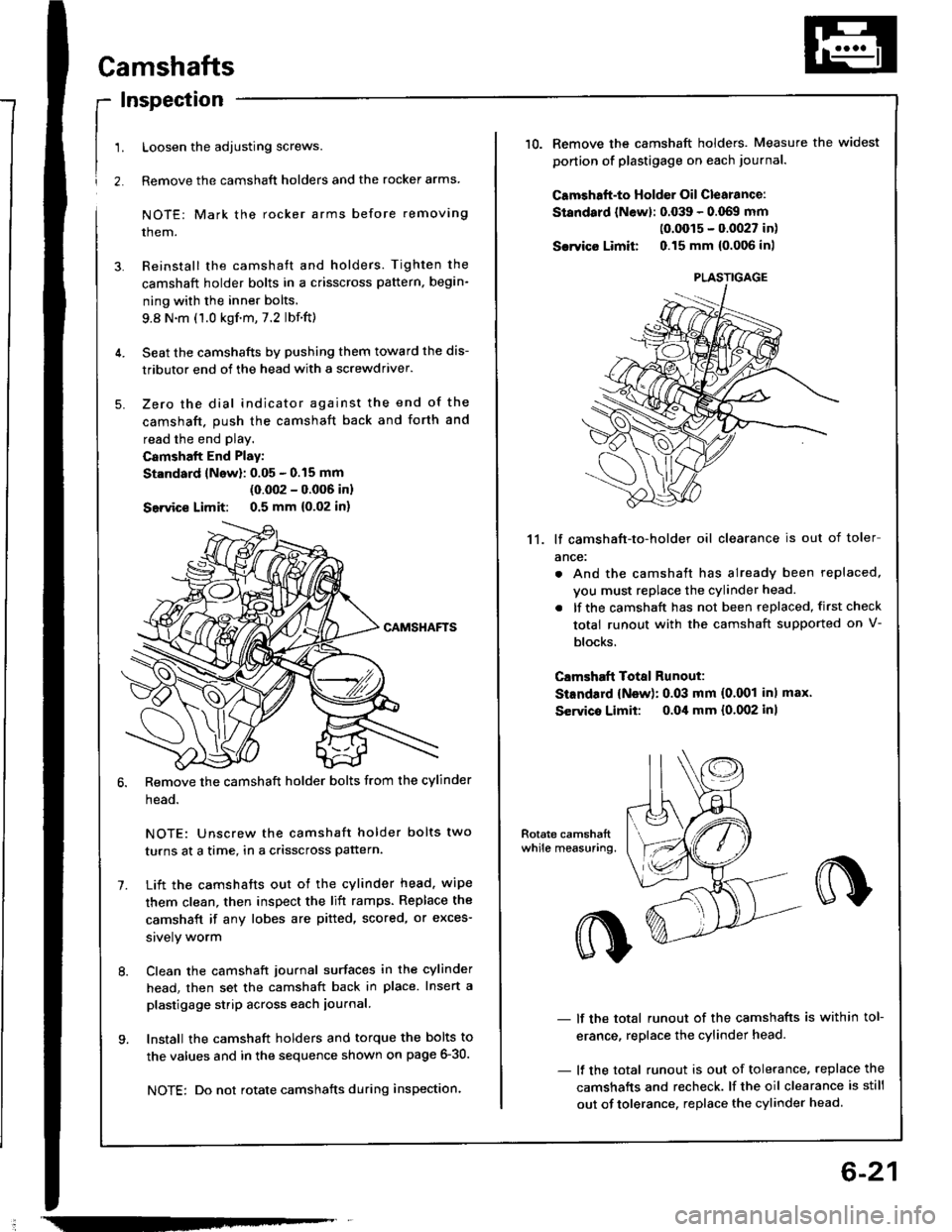
Camshafts
Inspection
Loosen the adjusting screws.
Remove the camshaft holders and the rocker arms
NOTE: Mark the rocker arms before removing
them.
Reinstall the camshaft and holders. Tighten the
camshaft holder bolts in a crisscross pattern, begin-
ning with the inner bolts.
9.8 N.m (1.0 kgf.m,7.2 lbf.ft)
Seat the camshafts by pushing them toward the dis-
tributor end of the head with a screwdriver.
Zero the dial indicator against the end of the
camshaft. push the camshaft back and forth and
read the end play.
Camshalt End Play:
St.ndard lNow): 0.05 - 0.15 mm
(0.002 - 0.006 inl
Seivice Limit: 0.5 mm {0,02 in)
Remove the camshaft holder bolts from the cylinder
head.
NOTE: Unscrew the camshaft holder bolts two
turns at a time, in a crisscross pattern.
Lift the camshafts out ot the cylinder head. wipe
them clean, then inspect the lift ramps. Replace the
camshaft if any lobes are pitted, scored, or exces-
srvely worm
Clean the camshaft journal surfaces in the cylinder
head, then set the camshaft back in place. Insert a
plastigage strip across each iournal.
Install the camshaft holders and torque the bolts to
the values and in the sequence shown on page 6-30.
NOTE: Do not rotate camshafts during inspection.
-
6-21
10.Remove the camshaft holders. Measure the widest
ponion of plastigage on each journa..
Camshaft-to Holder Oil Clearance:
Standard lNewl: 0.039 - 0.069 mm(0.0015 - 0.0027 in)
Sarvico Limit 0.15 mm {0.006 inl
11. lf camshaft-to-holder oil clearance is out of toler
ance:
. And the camshaft has already been replaced,
vou must replace the cylinder head.
. lf the camshaft has not been replaced, first check
total runout with the camshaft supported on V-
blocks.
Clmshaft Total Runout:
StEndard {New): 0.03 mm (0.001 inl max'
Servico Limit: o.Oil mm {0.002 inl
- lf the total runout of the camshafts is within tol-
erance, replace the cylinder head.
- lf the total runout is out of tolerance, replace the
camshafts and recheck. lf the oil clearance is still
out of tolerance. replace the cylinder head.
PLASTIGAGE
Page 92 of 1413
Cylinder Head
Installation (cont'dl
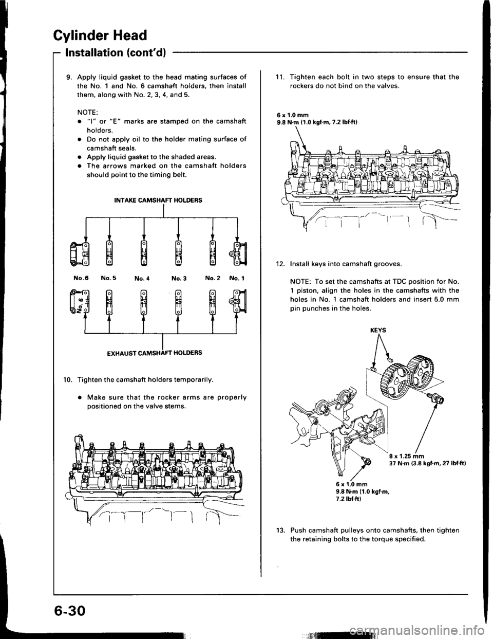
9. Apply liquid gasket to the head mating surtaces of
the No. 1 and No. 6 camshaft holders, then install
them, along with No. 2,3, 4, and 5.
NOTE:
o "1" or "E" marks are stamoed on the camshaft
holders.
. Do not apply oil to the holder mating surface of
camshaft seals.
. Apply liquid gasket to the shaded areas.
. The arrows marked on the camshatt holders
should point to the timing belt.
No.6 No.5No.2 No. 1
10. Tighten the camshaft holders temporarily.
. Make sure that the rocker arms are properly
positioned on the valve stems.
INTAKE CAMSHAFT HOLDERS
11. Tighten each bolt in two steps to ensure that the
rockers do not bind on the valves.
6r1.0mm9.8 N.m 11.0 kgf.m,7.2lbtft)
Install keys into camshaft grooves.
NOTE: To set the camshafts at TDC position for No.
1 piston, align the holes in the camshafts with the
holes in No. 1 camshaft holders and insert 5.0 mm
pin punches in the holes.
I r 1.25 mm37 N.m {3.8 kgf.m, 27 lbf.ttl
6x1.0mm9.8 N.m (1.0 kgf.m,7.2 tbtft)
Push camshaft pulleys onto camshafts, then tighten
the retaining bolts to the torque specified.
KEYS
13.
tfitml