Oil HONDA INTEGRA 1994 4.G Owner's Manual
[x] Cancel search | Manufacturer: HONDA, Model Year: 1994, Model line: INTEGRA, Model: HONDA INTEGRA 1994 4.GPages: 1413, PDF Size: 37.94 MB
Page 72 of 1413
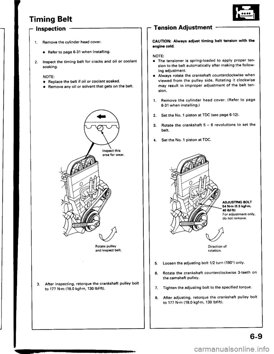
Timing Belt
Inspection
Remove the cylinder head cover.
. Reler to page 6-3'l when installing.
Inspect the timing belt for cracks and oil or coolant
soaking.
NOTE:
. Replace the belt if oil or coolant soaked.
. Rsmove any oil or solvent that gets on the belt.
Rotate pulley
and inspscr bell.
After inspecting, retorque the crankshaft pulley bolt
to 177 N'm ('18.0 kgf'm, 130 lbt'ft).
Tension Adjustment
CAUTION: Always Ediust timing belt tonsion with tho
cngin. cold.
NOTE:
. The tensionet is spring-loaded to apply proper ten-
sion to the belt automaticallv after making the follow-
ing adjustment.
. Always rotate the crankshaft counterclockwise when
viewed trom the pulley side Rotating it clockwise
may result in improper adjustment ot the belt ten-
sion.
Remove the cylinder head cover. (Refer to page
6-31 when installing.)
Set the No. 1 piston at TDC (see page 6-12).
Rotate the c.ankshaft 5 - 6 revolutions to set the
bslt.
4. Set the No. I piston at TDC.
3.
ADJUSNNG BOLT54 N.m (5.5 kqf.m,a0 rbr.ftlFor adiustment only,do not remove,
5.
6.
7.
8.
Direction olrolatlon.
Loosen the adiusting bolt 1/2 turn (180') onlv
Rotate the crankshaft counterclockwise 3-teeth on
the camshaft pulley.
Tighten the adjusting bolt to the specified torque.
After adjusting, retorque the crankshaft pulley bolt
to 177 N.m (18.0 kgl.m. 130 lbf.ft).
6-9
Page 74 of 1413
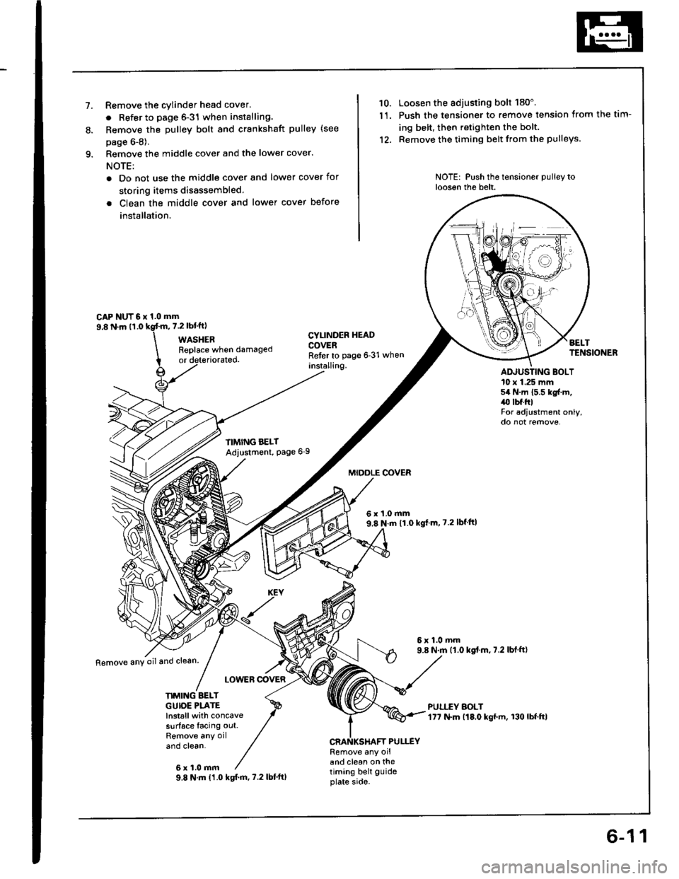
1.Remove the cylinder head cover.
. Refer to page 6-31 when installing.
Remove the Dulley bolt and crankshaft pulley (see
page 6-8).
Remove the middle cover and the lower cover.
NOTE:
. Do not use the middle cover and lower cover for
storing items disassembled.
. Clean the middle cover and lower cover before
installation.
CAP NUT 6 x 1.0 mm
10. Loosen the adjusting bolt 180'.
1'1. Push the tensioner to remove tension from the tim-
ing belt, then retighten the bolt.
12. Remove the timing belt from the pulleys.
NOTE: Push the tensioner pulley toloosen the belt.
8.
9.8 N.m 11.07.2 rbl.ftl
WASHER
orReplace when damaged
CYLINDEF HEADCOVERReter to page 6-31 wheninstalling.ADJUSTING BOLT10 x 1.25 mm54 N.m 15.5 kg{.m,/r0 lbf.ftlFor adjustment only,
TIMING BELTAdiustment, Page 6I
LOWEB @VER
MIDOLE COVER
6x1.0mm9.8 N.m 11.0 kgJ m, 7.2 lblftl
6x1.0mm9.8 N.m ('1.0 kgt.m,7.2 lbl fr)
Remove anY oiland clean
KE
6x1.0mm
NMING BELTGUIOE PLATElnstallwith concavesurface facing out.
and clean.CRANKSHAFT PULLEYRemove any oiland clean on ihetiming belt guideplate sido.9.8 N.m (1.0 kgtm,7.2lbt'ftl
6-11
Page 75 of 1413
Timing Belt
Installation
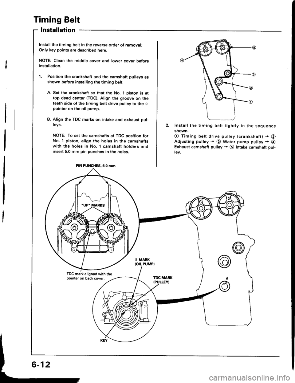
Install the timing belt in the revorce order of removal;
Only key points are described here,
NOTE: Cl€an the middle cover and lower cover beforeinstallation.
L Position the crankshaft and th€ camshaft pulleys asshown before installing the timing belt.
A. Set the crankshaft so that the No. 1 oiston is at
top dead center (TDC). Align the g.oovo on the
t€eth side of the timing belt d.ive pulley to the Opointer on the oil pump.
L Align the TDC marks on intake and exhaust pul-
tevs,
NOTE: To set the camshafts at TDC position for
No. 1 piston, align the holes in the camshafts
with the holes in No. l camshaft holders andinsert 5,0 mm pin punches in the holes.
PIN PUNCHES, 5.0 mm
2. lnstall the timing belt tightly in the sequence
snown.
O timing belt drive pulley {crankshaft) + @Adjusting pulley * @ Water pump pulley - @Exhaust camshaft pulley + @ Intake camshaft pul-
lev.
TDC mark align6d with thepointer on back cover,TDC MARK
6-12
Page 76 of 1413
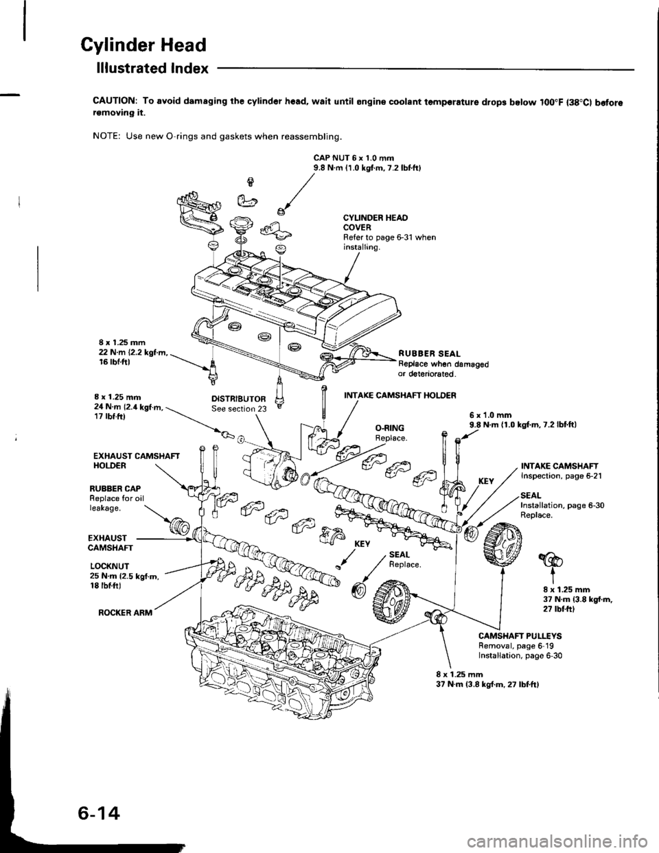
Cylinder Head
I x 1.25 mm22 N.m 12.2 kgt.m,16 rbf.ft)
lllustrated lndex
CAUTION: To avoid damaging the cylind6r hoad, waii until ongin€ coolant temporature drop3 below lOO"F (38"C) b€forersmoving it.
NOTE: Use new O rings and gaskets when reassembling.
CAP NUT 6 x 1.0 mtn9.8 N.m 11.0 kgtm,7.2lbtftl
e
et
CYLINDER HEADCOVERRefer to page 6-31 wheninstallang.
RUBBER SEALReplace when damagedor doteriorated.
I x 1.25 mm
EXHAUST CAMSHAFTHOI.DER
INTAKE CAMSHAFT HOI.DER
24 N.m 12.4 kgf.m, -. See section17 rbt.tr) --_r,_
__.|._6x1.0mm9.8 N.m {1.0 kgl.m,7.2lbf.ft)O-RINGRoplace.
RUBBER CAPReplace for oilleakage.
EXHAUSTCAMSHAFT
LOCKNUT
INTAKE CAMSHAFTInspection, page 5-21
SEALInstallation, page 6-30Replace.- 6tal --,
ffi;r
KEY
/./
"
@6
SEALReplace.'@
t25 N.m {2.5 kgf.m,18 tbtfiJ
ROCKER ARM
I x 1.25 mm37 N.m (3.8 kgt.m,27 rbtftt
CAMSHAFT PULLEYSRemoval, page 6 19Installation, page 6,30
8 x 1.25 mm37 N.m 13.8 kg{.m,27 lbfftl
Page 77 of 1413
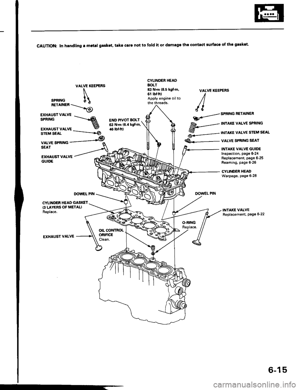
CAUTION: In h.ndling r m.t!l gr3kct, trko clrc not to fold it or dlmaga tho contact surfacr ol thr gaskat.
VAIVE XEEPERS
SPRING
RETAINER \.\...i6
r*#:-3STEM SEAL
VALVE SPRINGSEAT
CYUNDEB HEADBOLT&t N.m 18,5 kgl'm,61 tbf.ftlApply engine oiltothe threads.
END PIVOT BOLT6:t N.m l6.a kst'm,,16 lbl.ftl
VALVE KEEPERSI
JI
--../ SPf,ING RETAINEB
ED..-
$----
nrAxE vaLvE SPRING
S---- twtAKE vALvE STEM SEAL
€.---- valvE SPRING sEAT
EXHAUST VALVEGUII'E
INTAKE VAI-VE GUIT'EInsp€ction, pago S24R6placom6nt, pago 6-25Reaming, pag€ 6-26
CYUNDER HEADWarpage, page 6-28
INTAKE VALVEReplacement, Page 6_22
TX)WEL PINDOWEL PIN
CYLINDER HEAD GASKET{3 LAYERS OF METALIReolac6.
O.RINGReplac€.
EXHAUST VALVE
OIL CONTROLORIFICEClean.
--------ig
6-15
Page 79 of 1413
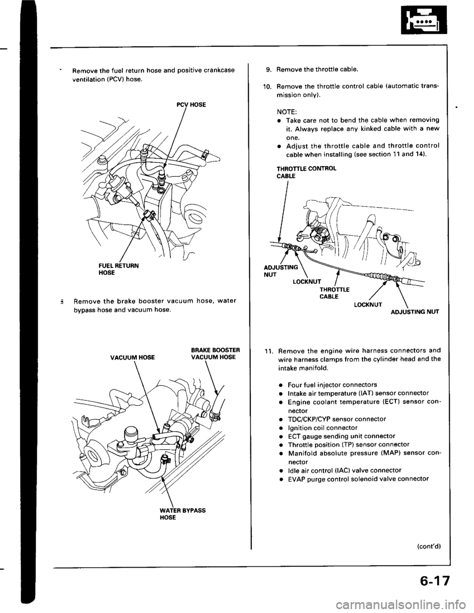
Remove the fuel return hose and positive crankcase
ventilation (PCV) hose.
Remove the brake booster vacuum hose, water
bypass hose and vacuum hose.
ERAKE BOOSTERVACUUM HOSE
HOSE
VACUUM HOSE
HOSE
9.
10.
Remove the throttle cable.
Remove the throttle control cable (automatic trans-
mission only).
NOTE:
. Take care not to bend the cable when removing
it. Always replace any kinked cable with a new
one.
. Adjust the throttle cable and throttle control
cable when installing (see section 11 and 14).
THROTTLE CONTROLCABLE
Remove the engine wire harness connectors and
wire harness clamps trom the cylinder head and the
intake manifold.
Four fuel injector connectors
Intake air temperature (lAT) sensor connector
Engine coolant temperature (ECT) sensor con-
necror
TDC/CKP/CYP sensor connector
lgnition coil connector
ECT gauge sending unit connector
Throttle position (TP) sensor connector
Manifold absolute Dressure (MAP) sensor con-
nector
ldle air control (lAC) valve connector
EVAP purge control solenoid valve connector
11.
a
a
a
a
a
a
a
a
a
(cont'dl
ATI'USTING
6-17
Page 83 of 1413
!
1.
2.
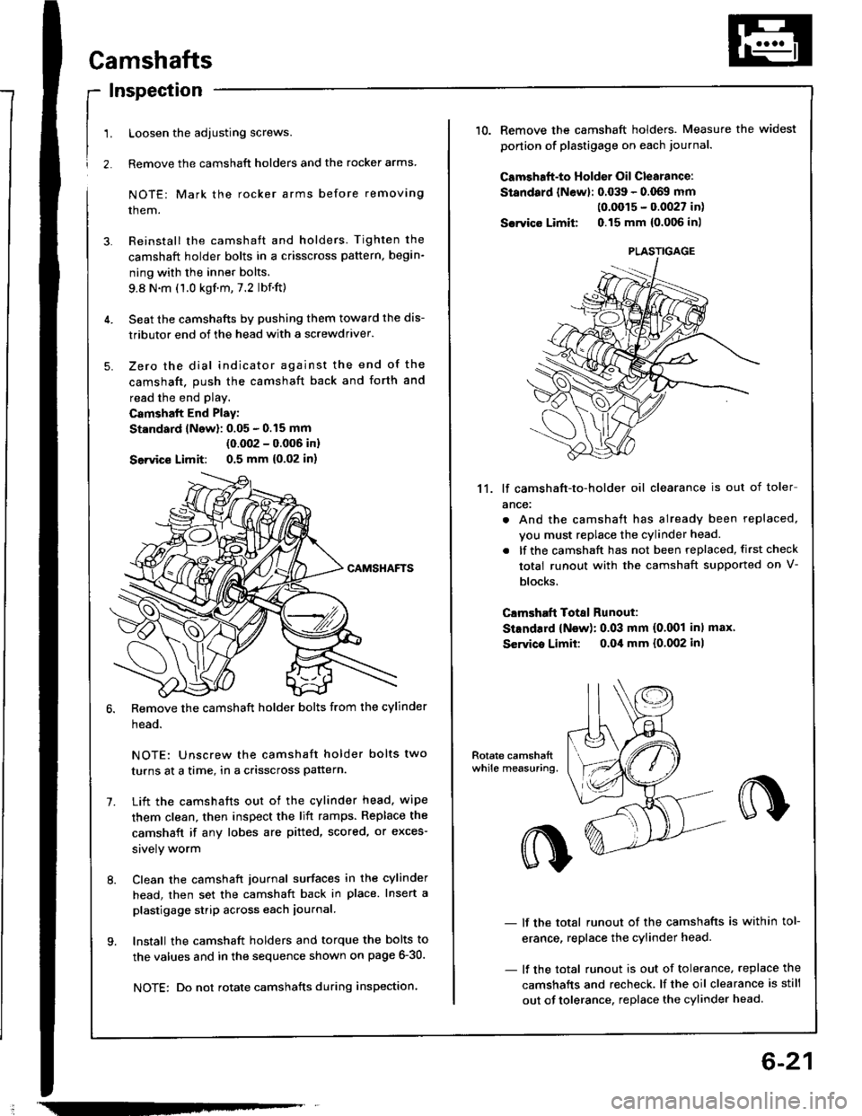
Camshafts
Inspection
Loosen the adjusting screws.
Remove the camshaft holders and the rocker arms
NOTE: Mark the rocker arms before removing
them.
Reinstall the camshaft and holders. Tighten the
camshaft holder bolts in a crisscross pattern, begin-
ning with the inner bolts.
9.8 N.m (1.0 kgf.m,7.2 lbf.ft)
Seat the camshafts by pushing them toward the dis-
tributor end of the head with a screwdriver.
Zero the dial indicator against the end of the
camshaft. push the camshaft back and forth and
read the end play.
Camshalt End Play:
St.ndard lNow): 0.05 - 0.15 mm
(0.002 - 0.006 inl
Seivice Limit: 0.5 mm {0,02 in)
Remove the camshaft holder bolts from the cylinder
head.
NOTE: Unscrew the camshaft holder bolts two
turns at a time, in a crisscross pattern.
Lift the camshafts out ot the cylinder head. wipe
them clean, then inspect the lift ramps. Replace the
camshaft if any lobes are pitted, scored, or exces-
srvely worm
Clean the camshaft journal surfaces in the cylinder
head, then set the camshaft back in place. Insert a
plastigage strip across each iournal.
Install the camshaft holders and torque the bolts to
the values and in the sequence shown on page 6-30.
NOTE: Do not rotate camshafts during inspection.
-
6-21
10.Remove the camshaft holders. Measure the widest
ponion of plastigage on each journa..
Camshaft-to Holder Oil Clearance:
Standard lNewl: 0.039 - 0.069 mm(0.0015 - 0.0027 in)
Sarvico Limit 0.15 mm {0.006 inl
11. lf camshaft-to-holder oil clearance is out of toler
ance:
. And the camshaft has already been replaced,
vou must replace the cylinder head.
. lf the camshaft has not been replaced, first check
total runout with the camshaft supported on V-
blocks.
Clmshaft Total Runout:
StEndard {New): 0.03 mm (0.001 inl max'
Servico Limit: o.Oil mm {0.002 inl
- lf the total runout of the camshafts is within tol-
erance, replace the cylinder head.
- lf the total runout is out of tolerance, replace the
camshafts and recheck. lf the oil clearance is still
out of tolerance. replace the cylinder head.
PLASTIGAGE
Page 85 of 1413
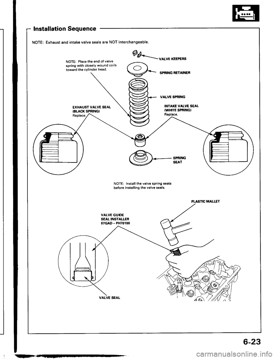
Installation Sequence
NOTE: Exhaust and intake valve seals ate NOT interchangeable.
NOTE: Place th€ 6nd oI valve
spring with closelY wound coils
towrrd th€ cylinder head.
EXHAUST VALVE SEAL{8LACK SPRING}Replace.
NOTE: Installth€ v6lvo spring s€atsbeforo instslling the valv6 sesls.
@/.-uo.**.r..",
SPRNG NETAINER
@*_-.tt*
PLASTIC MALIIT
.tIF"F-
6-23
Page 86 of 1413
Valves, Valve Springs and
Valve Seals
Valve lnstallation
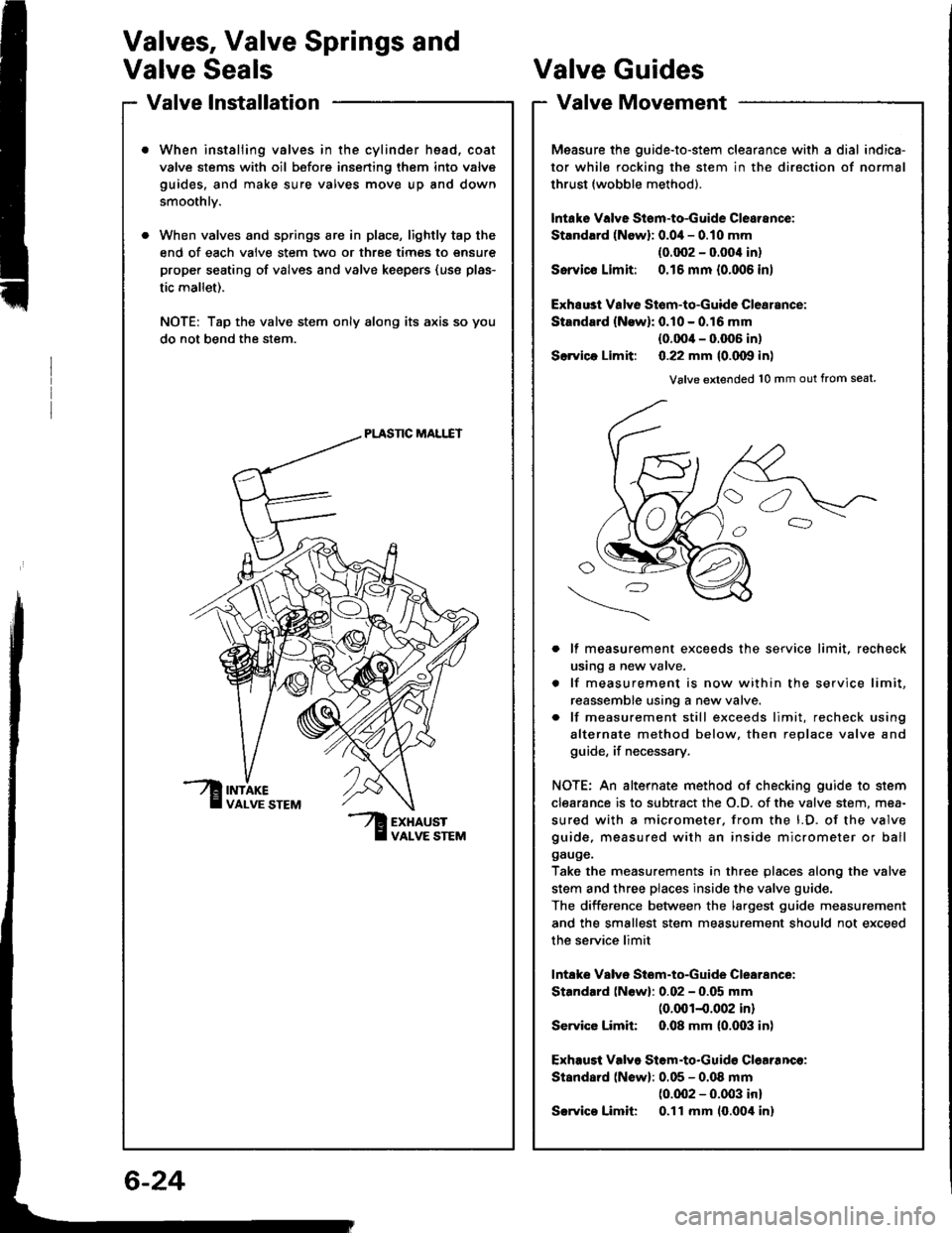
When instaliing valves in the cylinder head, coat
valve stems with oil before insening them into valve
guides, and make sure valves move up and down
smoothlv.
When valves and springs are in place, lightly tap the
end of each valve stem two or three times to snsure
proper seating of valves and valve keepsrs (use plas-
tic mallet).
NOTE: Tap the valve stem only along its axis so you
do not bend the stem.
PLASNC MALI.IT
?ur
Valve Guides
Valve Movement
Measure the guide-to-stem clearance with a dial indica-
tor while rocking the stem in the direction of normal
thrust (wobble method).
lntake Valve Stsm-to-Guide Clearance:
Strndlrd (Newl: 0.0i1- 0.10 mm
(0.002 - 0.004 in)
Ssrvicc Limit: 0.16 mm {0.006 in)
Exhsust Valye Stom-to-Guide Clearance:
Standard {N€w): 0.10 - 0.16 mm
{0.0O'l - 0.006 in)
Slrvica Limit: 0.22 mm {0.000 in)
Valve extended 10 mm out from seat
lf measurement exceeds the service limit, recheck
using a new valve.
lf measurement is now within the service limit,
reassemble using a n€w valve.
lf measurement still exceeds limit, recheck using
alternate method below. then replace valve and
guide, if necessary.
NOTE: An alternate method of checking guide to stem
clearance is to subtract the O.D. of the valve stem, mea-
sured with a micrometer. from the l.D. of the valve
guide, measured with an inside micrometer or ball
gauge.
Take the measurements in three places along the valve
stem and three places inside the valve guide.
The diiference between the largest guide measurement
and the smallest stem measurement should not exceed
the service limit
lntake Valve Stom-to-Guide Clearance:
Standard (Newl: 0.02 - 0.05 mm(0.001-0.002 in)
Service Limit 0.08 mm (0.003 in)
Exhaust Valve Stom.to.Guid€ Clearanco:
Standard (Newl: 0.05 - 0.08 mm(0.002 - 0.003 inl
Srrvico Limit 0.ll mm 10.00't inl
6-24
Page 88 of 1413
Valve Guides
Replacement {cont'd}
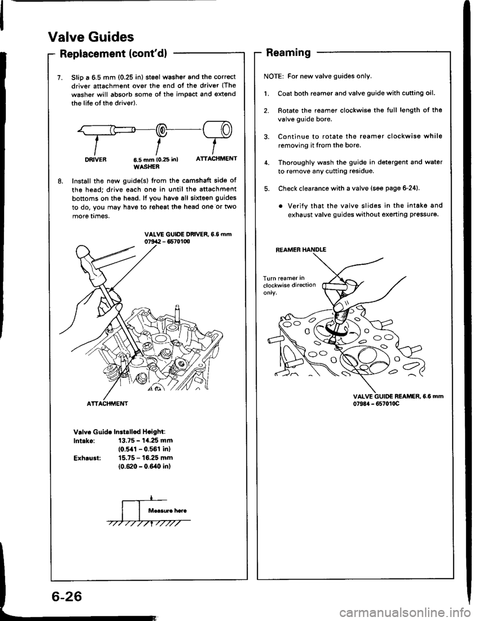
7. SliD a 6.5 mm {0.25 in) stsel washor and the correct
driver attachment over the end of the driver {The
washer will absorb some of the impact and extend
the life of the driver).
.,F-q-re
tt-T-IIttlDRVEn 6,5 mm t0.25 in) ATTACHMENT
WASHER
8, Install the new guide(s) from the camshaft side of
the head; drive each one in until the attachment
bottoms on the head. lf you have 8ll sixteen guides
to do, vou may have to reheat the head one or two
more I|mes.
Valv6 Guida Instsllod Hcight:
lntaks: 13.75 - 14.25 mm
(o.sal - 0.561 inl
Exhru3t: 15.75 - 16.25 mm
{0.620 - 0.640 in}
Reaming
NOTE: For new valve guides only.
Coat both reamer and valve guide with cutting oil.
Rotate the reamer clockwise the full length of the
valve guide bore.
Continue to rotate the reamet clockwise while
removing it from the bore.
Thoroughly wash the guide in detergent and water
to remove any cutting residue.
Check clearance with a valve (see page 6-24).
. Verify that the valve slides in the intake 8nd
exhaust valve guides without ex€rting pressure.
VALVE GUII'E REAMER, 6.6 MM
079E4 - 667ot0c
REAMER HANDLE
s