Oil HONDA INTEGRA 1994 4.G Repair Manual
[x] Cancel search | Manufacturer: HONDA, Model Year: 1994, Model line: INTEGRA, Model: HONDA INTEGRA 1994 4.GPages: 1413, PDF Size: 37.94 MB
Page 148 of 1413
Main Bearings
Clearance
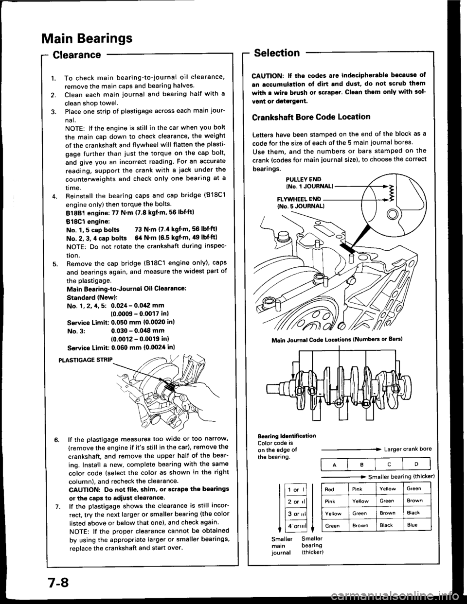
To check main bearing-to-journal oil clearance,
remove the main caps and bearing halves.
Clean each main journal and bearing half with a
clean shop towel.
Place one strip of plastigage across each main iour-
nal.
NOTE: lf the engine is still in the car when you bolt
the main caD down to check clearance, the weight
of the crankshaft and flywheel will flatten the plasti-
gage further than just the torque on the cap bolt,
and give you an incorrect reading. Fot an accurate
reading, support the crank with a iack under the
counterweights and check only one bearing at a
trme.
Reinstall the bearing caps and cap bridge (818C1
engine only) then torque the bolts.
81881 engine:77 N'm (7.8 kgf'm,56lbl'ft)
818C1 engine:
No. 1,5 cap bolts 73 N'm (7.'l kgt'm,56lbf'ftl
No. 2, 3, 4 cap bolts 6a N'm (6.5 kgf'm, 49 lbf'ftl
NOTE: Do not rotate the crankshaft during inspec-
tron,
Remove the cap bridge (818C1 engine only), caps
and bearings again, and measure the widest part oJ
the plastigage.
Main Bearing-to-Journal Oil Cl€arance:
Standard (Newl:
No. 1, 2, 4, 5: 0.024 - 0.042 mm
10.0009 - 0.0017 inl
Service Limit: 0.050 mm {0.0020 inl
No. 3:0.030 - 0.0,18 mm(0.0012 - 0.0019 inl
Ssrvice Limit: 0.060 mm {0.0024 inl
PLASTIGAGE STNIP
lf the plastigage measures too wide or too narrow,
(remove the engine if it's still in the car), remove the
crankshaft. and remove the upper half of the bear-
ing. Install a new. complete bearing with the same
color code (select the color as shown in the right
column), and recheck the clearance.
CAUTION: Do not file, shim, or scrapo ihe bo.rings
or the caps to adiust clearance.
lf the plastigage shows the clearance is still incor-
rect, try the next larger or smaller bearing (the color
listed above or below that one), and check again.
NOTE: lf the Droper clearance cannot be obtained
by using the appropriate larger or smaller bearings,
reolace the crankshaft and start over.
Selection
CAUTION: lf ths codes are indeciphorable becau3o ot
an lccumulation ol dirt and dust, do not gcrub thgm
with a wirs brush or gcrapsr. Clean them only with 3ol-
vont or doisrggnt.
Crankshaft Bore Code Location
Letters have been stamped on the end of the block as a
code for the size of each of the 5 main journal bores
Use them, and the numbers or bars stamped on the
crank (codes for main journal size), to choose the correct
bearings.
B..ring ld.ntificrtionColor code is
on the edge otthe bearang.Larger crank Dore
Mlin Joumal CodG Locttion3 (Numbors or gaBl
IcD
tr;;lIl
Itr-tl
lE;tl I tlHlt
I Lo.""li L
Smaller Smallermsin bearingjournal (thicker)
-------.r> smaller bearing (thicker)
G'een
Gre€^
GreenBlacr
GreenElackBlue
7-8
Page 149 of 1413
ConnectingRod Bearings
ClearanceSelection
CAUTION: lf the codss are indeciphsrable bocause of
an accumulation of dirt and dust. do not scrub tham
with a wiro brush or scraper. Clean them only with sol-
vont or dotetgenl.
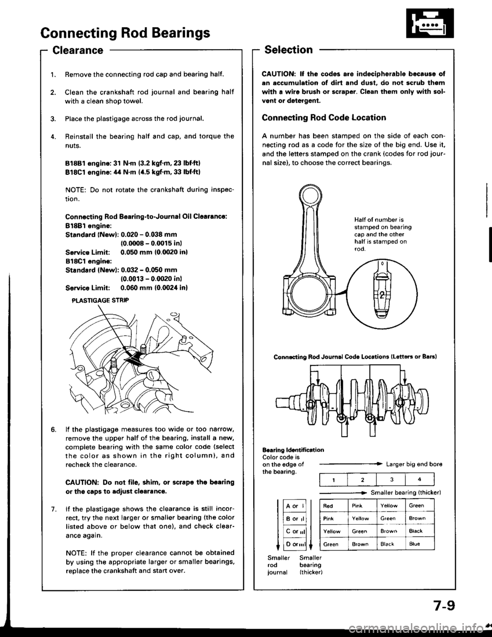
Connecting Rod Code Location
A number has been stamped on the side of each con-
necting rod as a code for the size of the big end. Use it,
and the letters stamped on the crank (codes for rod jour-
nal size), to choose the correct bearings.
tF;l I tl-lf
liBor'rll I
lEalll t
I 1o.,,,'ll L
Smaller Smallerrod bearingjournal (thicker|
Half of number isstamped on bearingcap and the otherhalf is stamped onrod.
Conn.cting Rod Joumsl Codc LocatioN lLotteE or B.trl
Berring ldcntification
t23
Color code ison the edge ofthe bearing.Larger big end bore
Smaller bearing {thicker)
RedGr€€n
Elack
Bla€kBlue
1. Remove the connecting rod cap and bearing half.
2. Clean the crankshaft rod journal and bea.ing half
with a clean shoo towel.
3. Place the plastigage across the rod journal.
4. Reinstall the bearing half and cap, and torque the
nuts.
81881 sngino: 31 N'm 13.2 kgf.m,23 lbt'ft)
818C1 sngine: 4,1 N.m 14.5 kgf.m. 33 lbf'ft}
NOTE: Do not rotate the crankshaft during inspec-
tion.
Connecting Rod B€aring-to-Journal Oil Clcalancr:
8l88l ongine:
Standard (New): 0.020 - 0.038 mm
{0.0008 - 0.0015 in)
Servica Limit: 0.050 mm (0.0020 inl
818C1 engin€:
Standard (New): 0.032 - 0.050 mm
(0.0013 - 0.(XP0 inl
Service Limit: 0.060 mm (0.0024 in)
ll the plastigage measures too wide or too narrow,
remove the upper half of the bearing. install a new,
complete bearing with the same color code (select
the color as shown in the right column), and
recheck the clearance.
CAUTION: Do not file, shim, or scrape lhe bearing
or the capg tq adiust clgaranca.
lf the plastigage shows the clearance is still incor-
rect, try the next la.ger or smaller bearing {the color
listed above or below that one), and check clear-
ance again.
NOTE: lf the proper clearance cannot be obtained
by using the appropriate larger or smaller bearings,
reolace the crankshaft and stan over.
1.
PLASTIGAGE STRIP
Page 150 of 1413
Crankshaft
Removal
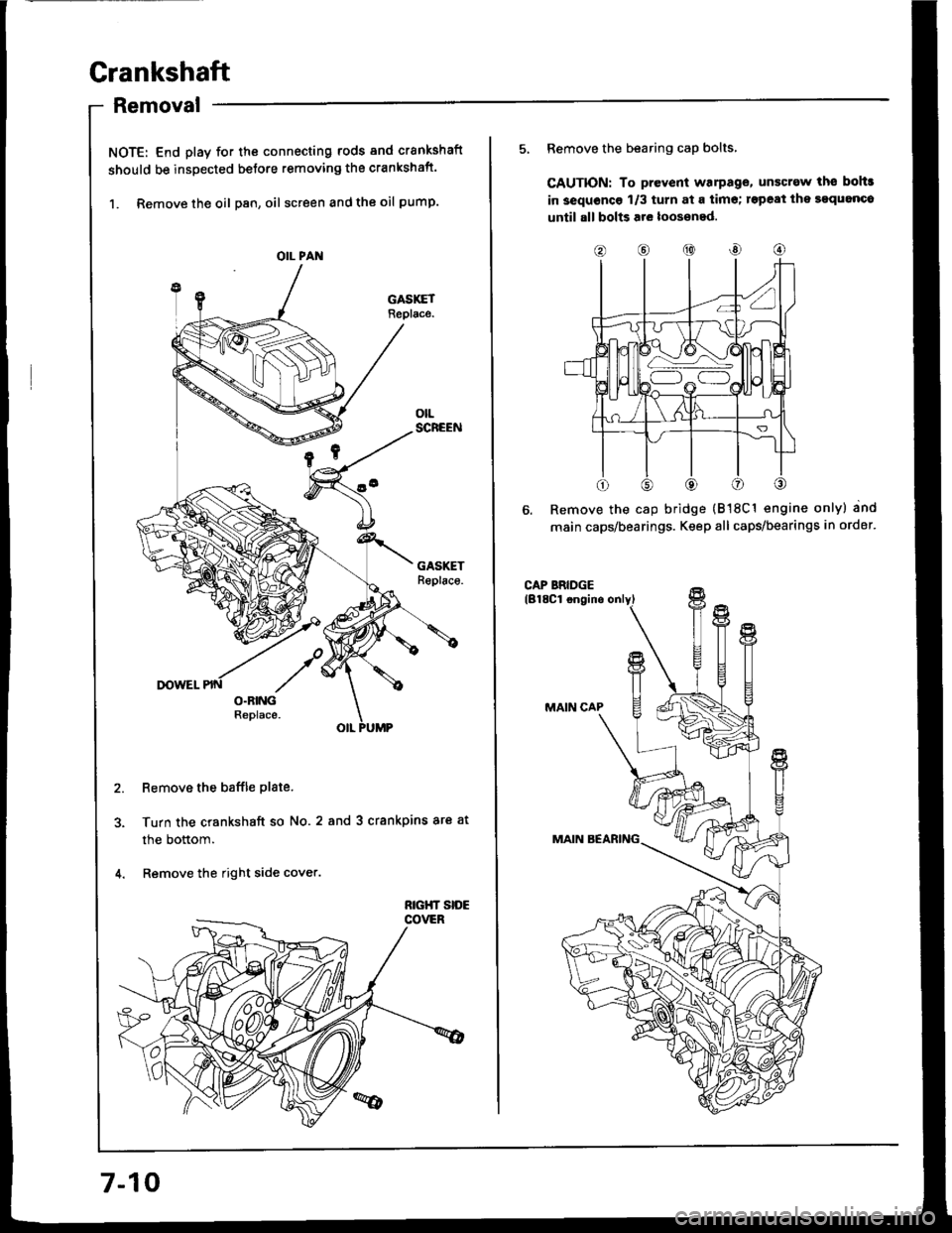
NOTE: End play for th€ connecting rods and crankshaft
should be inspected betore removing the crankshaft.
1. Remove the oil Dan, oil screen and the oil pump.
Remove the baffle plate.
Turn the crankshaft so No.2 and 3 crankpins ar€ at
the bottom.
Remove the right side cover.
OIL PAN
7-10
o@@
5, Remove the bearing cap bolts,
CAUTION: To prevent warPag€, unscrew ths bohr
in 3equoncg 1/3 turn at a tim€; rspeat ihe sgquanco
until all bolts are loos€ned.
Remove the cap bridge {818C1 engine only} and
main caps/bearings. Keep all caps/bearings in order.
Page 151 of 1413
7.
8.
11.
9.
10.
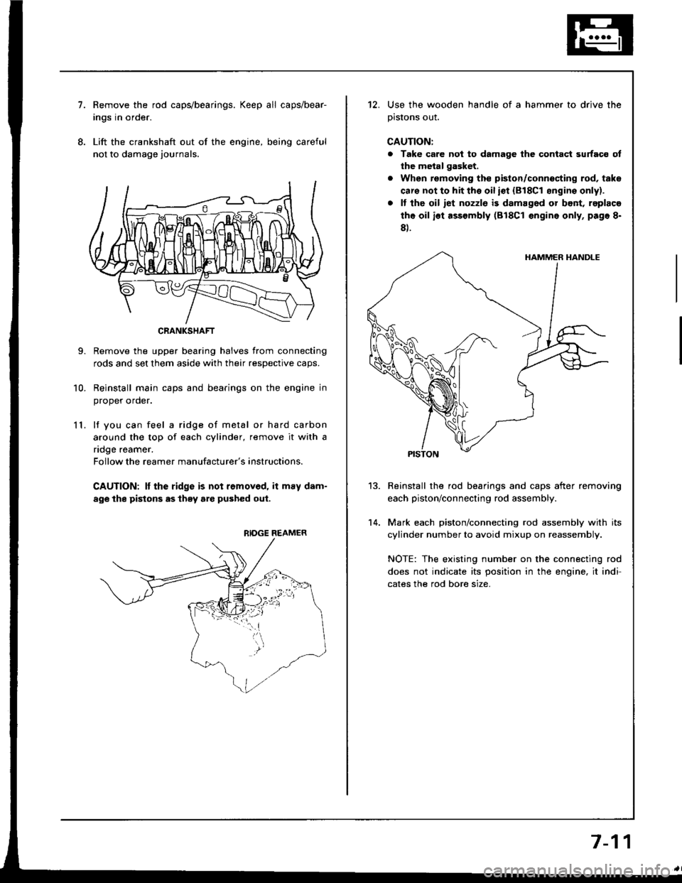
Remove the rod caps/bearings. Keep all caps/bear-
ings in order.
Lift the crankshaft out of the engine, being careful
not to damage journals.
Remove the upper bearing halves from connecting
rods and set them aside with their resDective caDs.
Reinstall main caps and bearings on the engine in
oroDer order.
lf you can feel a ridge of metal or hard carbon
around the top of each cylinder, remove it with a
ndge reamer.
Follow the reamer manufacturer's instructions.
CAUTION: It the ridge is not removed, it may dam-
age the pistons as they are pushed oul.
CRANKSHAFT
RIDGE REAMER
12. Use the wooden handle of a hammer to drive the
prslons ouI.
CAUTION:
a Take care not to damage the contact surfaco ot
the metal gasket.
. When removing the piston/connecting rod, taks
caro not to hit the oil iot {818C1 sngins onlyl.
. It tho oil iet nozzlo is damag6d or bont, replaco
the oil ist assembly (818C1 engine only, page 8-
8).
Reinstall the rod bearings and caps after removing
each piston/connecting rod assembly.
Mark each piston/connecting rod assembly with its
cylinder number to avoid mixup on reassembly.
NOTE: The existing number on the connecting rod
does not indicate its position in the engine, it indi-
cates the rod bore size.
13.
14.
7-11
Page 152 of 1413
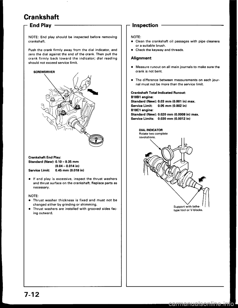
EndPlay
NOTE; End play should be inspected before removing
crankshaft.
Push the crank firmly awav from the dial indicator, and
zero the dial against the end of the crank. Then pull the
crank firmly back toward the indicator; dial reading
should not exceed service limit.
Crankshaft End Play:
Standard (New): 0.10 - 0.35 mm
(0.04 - 0.01i| inl
S€rvic€ Limit 0.i15 mm (0.018 inl
. lf end play is excessive, inspect the thrust wash€rs
and thrust surface on the crankshaft. Replace pans as
necessary.
NOTE:
Thrust washer thickness is fixed and must not be
changed either by grinding or shimming.
Thrust washers are installed with grooved sides fac-
ing outward.
Crankshaft
lnspection
. Clean the crankshatt oil passages with pipe cleaners
or a suitable brush.
. Check the keyway and threads.
Alignment
Measure runout on all main journals to make sure the
crank is not bent.
The differ€nce between measurements on each jour-
nal must not be more than the service limit.
Crank3haft Total lndicatod Runout:
Bl8Bl engins:
Sisndod {Nsw): 0.03 mm {0.001 in) max.
Sorvice Limit: 0.05 mm {0.002 inl
818C1 engin€:
Standard {Nsw): 0.020 mm (0.0008 in} mar.
SGrvice Limits: 0.030 mm 10.0012 in)
OIAL INDICATORRotate tlvo completerevolutions.
Support with lathe-
7-12
Page 154 of 1413
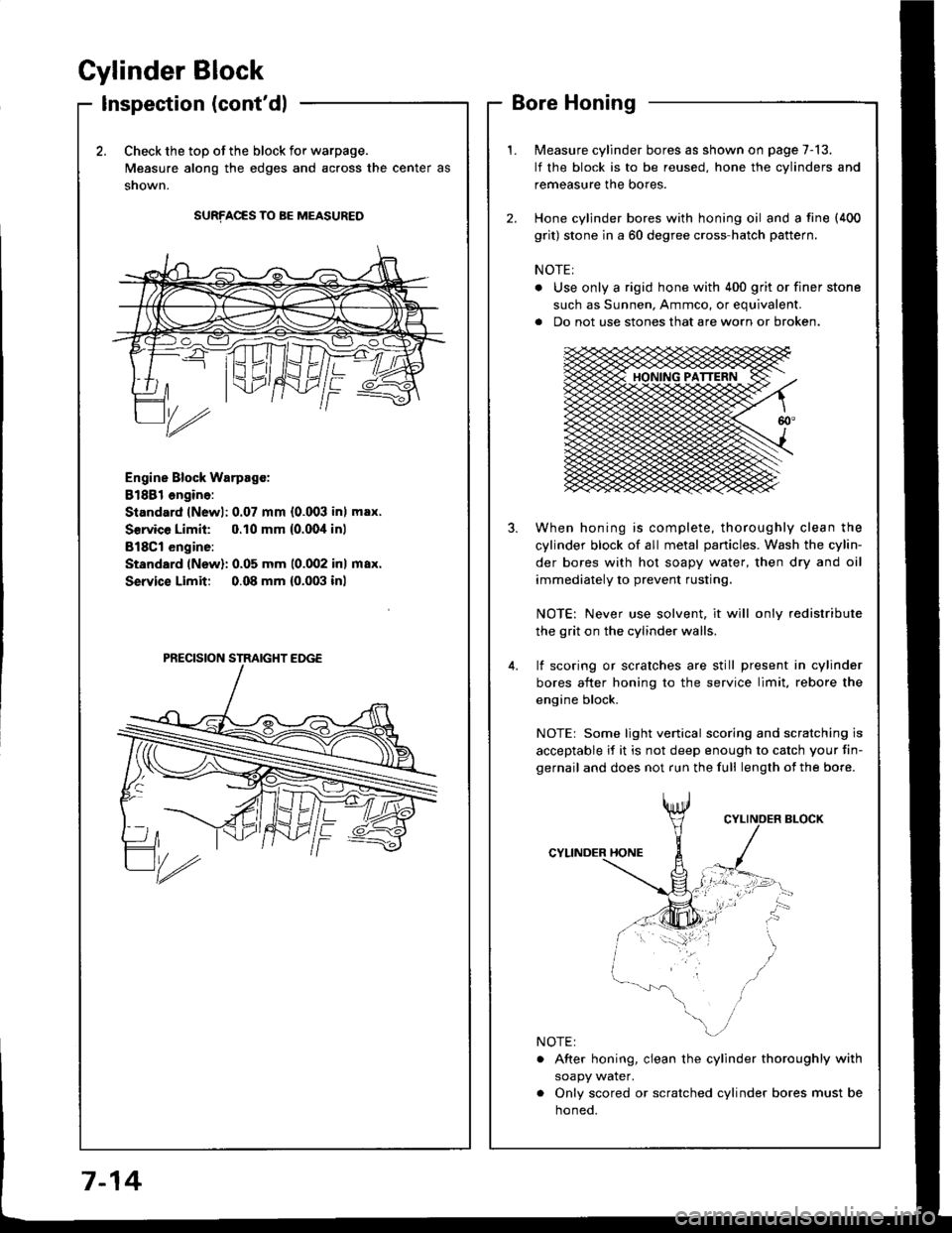
Cylinder Block
Inspection (cont'dl
2.Check the top of the block for warpage.
Measure along the edges and across the center as
snown.
SURFACES TO BE MEASURED
Engine Block Warpsgc:
81881 ongine:
Standard lNewl: 0.07 mm {0.003 inl max.
Service Limil: 0.10 mm {0.00,1inl
B18Cl engine:
Standard (New): 0.05 mm 10.002 inl max.
Service Limit 0.08 mm {0.003 inl
Measure cylinder bores as shown on page 7-13.
lf the block is to be reused, hone the cylinders and
remeasure the bores.
Hone cylinder bores with honing oil and a fine (400
grit) stone in a 60 degree cross-hatch pattern.
NOTE:
. Use only a rigid hone with 400 grit or finer stone
such as Sunnen, Ammco, or equivalent.
a Do not use stones that are worn or broken.
When honing is complete, thoroughly clean the
cylinder block of all metal panicles. Wash the cylin-
der bores with hot soapy water, then dry and oil
immediately to prevent rusting.
NOTE: Never use solvent, it will only redistribute
the grit on the cylinder walls.
lf scoring or scralches are still present in cylinder
bores after honing to the service limit, rebore the
engine block.
NOTEr Some light venical scoring and scratching is
acceptable if it is not deep enough to catch your fin-
gernail and does not run the full length of the bore.
CYLINDER HONE
. After honing, clean the cylinder thoroughly with
soapy water.
. Only scored or scratched cylinder bores must be
noneo.
7-14
Page 156 of 1413
Piston
lnstallation
'1.
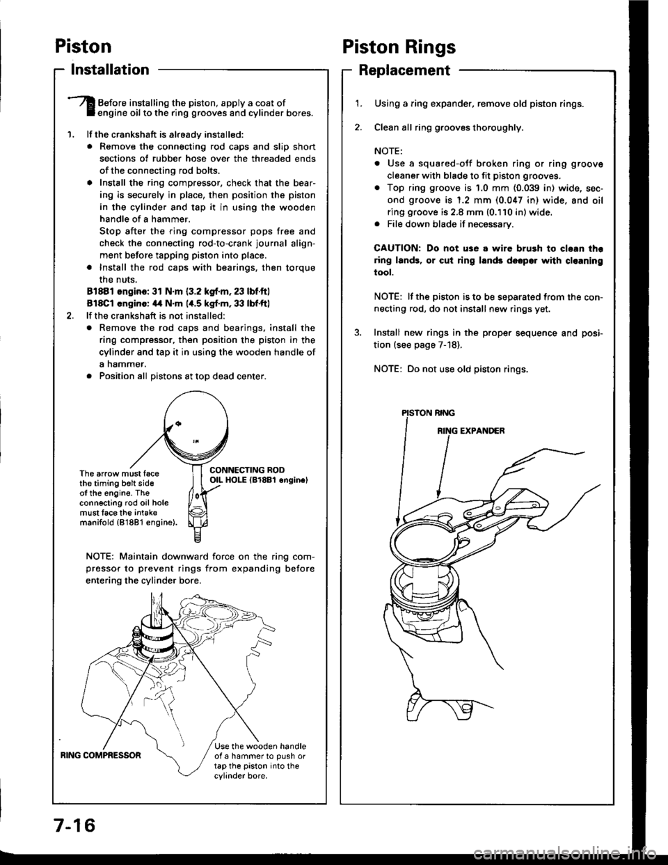
Before installing the piston, apply a coat ofengine oil to the ring grooves and cylinder bores.
lf the crankshaft is already installed:
. Remove the connecting rod caps and slip short
sections of rubber hose ove. the threaded ends
of the connecting rod bolts.
a Install the ring compressor, check that the bear'
ing is securely in place, then position the piston
in the cylinder and tap it in using the wooden
handle of a hammer.
Stop after the ring compressor pops free and
check the connecting rod-to-crank journal align-
ment before tapping piston into place.
. Install the rod caps with bearings, then torque
the nuts,
81881 ongino: 31 N.m {3.2 kgf.m, 23 lbf.ftl
818C1 cngino: 44 N'm 1,t.5 kgf.m, 33 lbf.ftl
lf the crankshaft is not installed:
o Remove the rod caps and bearings. install the
ring compressor, then position the piston in the
cylinder and tap it in using the wooden handle of
a nammer.
. Position all Distons at toD dead center.
CONNECTING RODOIL HOI-E (Br8Bl onginelThe arrow must facethe timing belt sideof the engine. Theconnecting rod oil holemust lace the intak€manifold {81881 €ngine).
NOTE: Maintain downward force on the ring com-
pressor to prevent rings from expanding before
entering the cylinder bore,
BING COMPRESSORUse the wooden handleof a hammer to push ortap the piston into thecylinder bore.
Piston Rings
Replacement
1.Using a ring expander, remove old piston rings.
Clean all ring g.ooves thoroughly.
NOTE:
. Use a squared-oJf broken ring or ring groove
cleaner with blade to fit piston grooves.
. Top ring groove is 1.0 mm (0.039 in) wide, sec-
ond groove is 1.2 mm (0.047 in) wide. and oil
ring groove is 2.8 mm (0.110 in) wide.. File down blade if necessary.
CAUTION: Do not use a wire brush to cloan thr
ring lands, or cut ring lands dsopo. with cl€aning
tool.
NOTE: lf the piston is to be separated from the con-
necting rod, do not install new rings yet.
Install new rings in the prope. sequence and posi-
tion (see page 7-18).
NOTE: Do not use old piston rings.
Page 157 of 1413
I
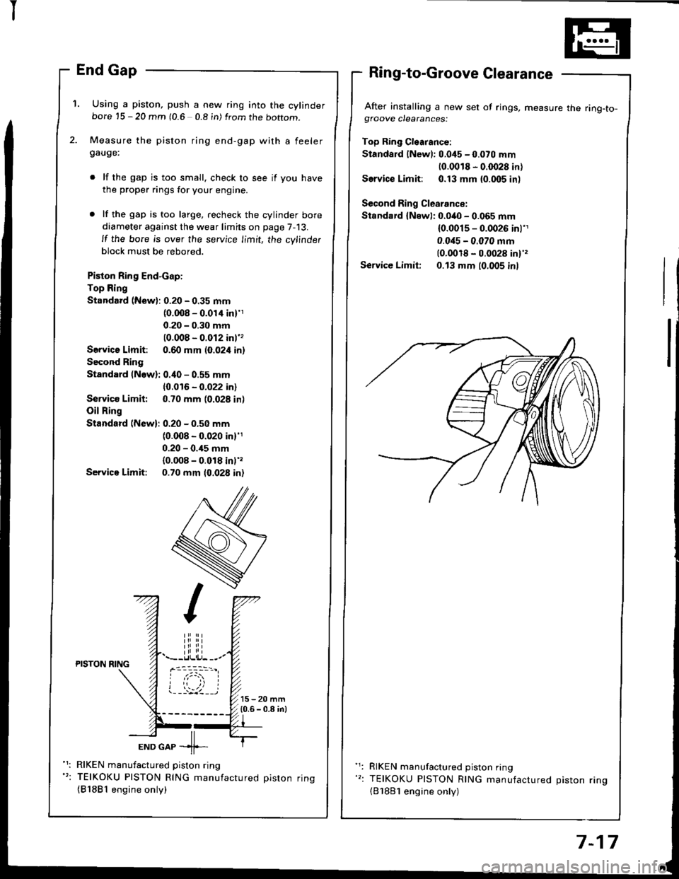
'1. Using a piston, push a new ring into the cylinderbore 15 - 20 mm (0.6 0.8 in) from the boftom.
Measure the piston ring end-gap with a feelergauge:
lf the gap is too small. check to see if you have
the proper rings for your engine.
lf the gap is too large, recheck the cylinder bore
diameter against the wear limits on page 7-13.
ll the bore is over the service limit, the cylinder
block must be rebored.
Piston Ring End-cap:
Top Ring
Standard (New): 0.20 - 0.35 mm(0.008 - 0.01'l inl'1
0.20 - 0.30 mm
10.008 - 0.012 inl''
Servica Limit: 0.60 mm (0.024 in)
Second Ring
Standard (Now): 0.40 - 0.55 mm
10.016 - 0.022 in)
Service Limit: 0.70 mm (0.028 in)
Oil Ring
Standard (New): 0.20 - 0.50 mm(0.008 - 0.020 in)'1
0.20 - 0.,15 mm
{0.008 - 0.018 inl',
Servica Limit: 0.70 mm 10.028 in)
After installing a new set of rings, measure the ring-to-gfoove clearances:
Top Ring Cl€arance:
Standard lNewl: 0.045 - 0.070 mm
10.0018 - 0.0028 in)
Service Limit: 0.13 mm {0.005 inl
Second Ring Clearance:
Standard {Newl: 0.040 - 0.065 mm(0.0015 - 0.0026 inl'1
0.0i15 - 0.070 mm(0.0018 - 0.0028 in)',
Service Limit: 0.13 mm (0.005 inl
iliiii.--r.llli.j- --.-PISTON NING
ioi
---'z llEND GAP -11--
RIKEN manufactured piston ring
TEIKOKU PISTON RING manufactured oiston rinq
{81881 engine only)
RIKEN manufactured piston ring
TEIKOKU PISTON RING manufactured Diston rino(B'1881 engine only)
7-17
Page 158 of 1413
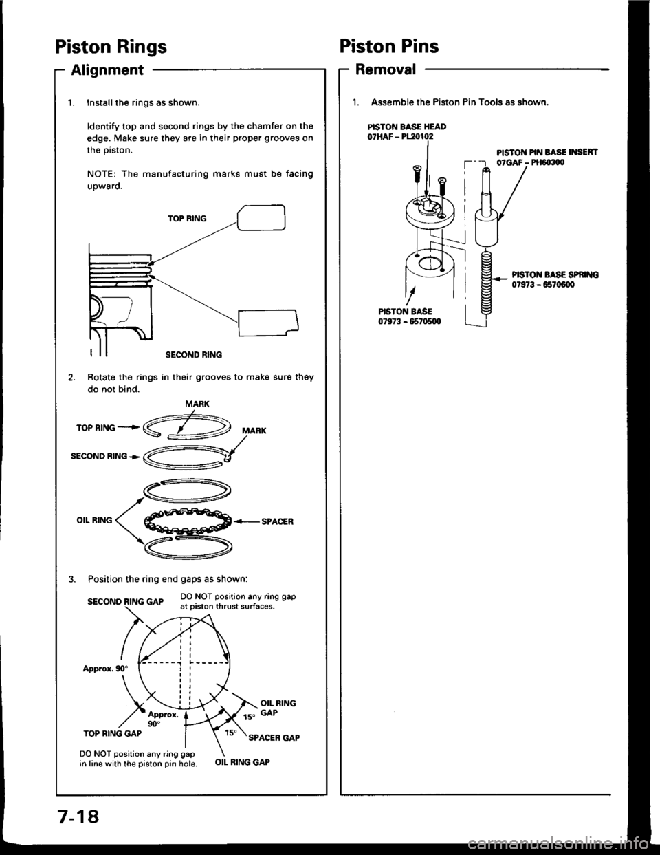
Piston Rings
Alignment
1.Installthe rings as shown.
ldentify top and second rings by the chamfer on the
edge. Make sure they are in their proper grooves on
the prston.
NOTE: The manufacturing marks must be facing
upwaro.
TOP BING
OIL RINGSPACER
3. Position the ring end gaps as shown:
DO NOT position any ring gapsEcoNo R|NG GAp -.- :': :.-"' : - ' '----'-- { _- - - at prston thrust surfaces.
App.ox. 90"
OIL RING
ls" GAP
TOP BING GAPSPACER GAP
Rotate the rings
do not bind.
DO NOT position any ring gapin line with the piston pin hole.
SECOND RING
in their grooves to make sure they
MARK
OIL RING GAP
Piston Pins
Removal
1. Assemble the Piston Pin Tools as shown.
PISTO]T PIN BASE INSEN|T--r otGAF- PH6{t1,0
PISTON BASE HEAD
--l
PISTON BASE SP '{G07973 - 65r06{X'
7-18,
Page 159 of 1413
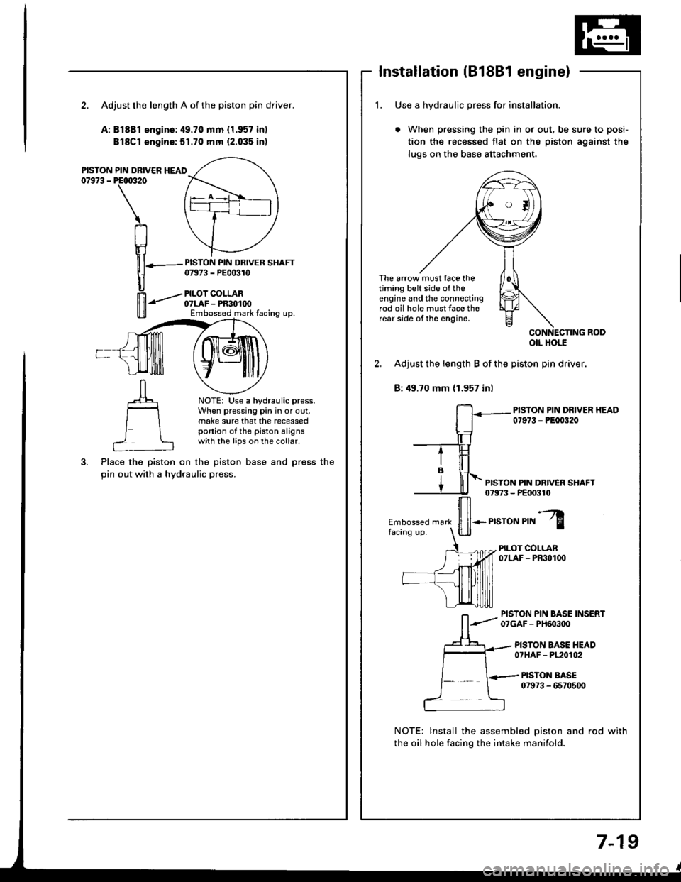
Installation (B18Bl engine)
2. Adjust the length A of the piston pin driver.
A:81881 engine:49.70 mm {1.957 inl
Bl8Cl €ngin€:51.70 mm {2.035 inl
PISTON PIN DRIVER HEAD07973 - PE00320
PISTON PIN DRIVER SHAFT07973 - PE00310
PILOI COLLAR07LAF - PR30100Embossed mark facing up.
NOTE: Use a hydraulic press.When pressing pin in or out,make sure that the recessedportion of the piston alignswith the lips on the collar.
Place the piston on the piston base and press the
pin out with a hydraulic press.
1. Use a hvdraulic oress for installation.
When pressing the pin in or out, be sure to posi-
tion the recessed flat on the piston against the
lugs on the base attachment.
The arrow must face thetiming belt side o{ theengine and the connectingrod oil hole must face therear side of the engine,
otl Hols
2. Adjust the length B of the piston pin driver.
B: 49.70 mm (1.957 inl
PISTON PIN DRIVER HEAD07973 - PEfl)320
PISTON PIN DR|VEN SHAFT079?3 - PE|X)310
Embossed mark
ffi*.r,"ror","l
PILOT COLLAN07LAF - PF301(x)
PISTON PIN BASE INSERT07GAF- PH603oO
PISTON BASE HEAD07HAF - PL20t02
PISTON BASE079?3 - 6570500
NOTE: lnstall the assembled piston and rod with
the oil hole facing the intake manifold.
7-19