ac circuit HONDA INTEGRA 1994 4.G Owner's Manual
[x] Cancel search | Manufacturer: HONDA, Model Year: 1994, Model line: INTEGRA, Model: HONDA INTEGRA 1994 4.GPages: 1413, PDF Size: 37.94 MB
Page 291 of 1413
Fuel Supply System
Fuel Injectors
- --l- - \-l-l
116l- -ltc l-/---r- / ---i- \
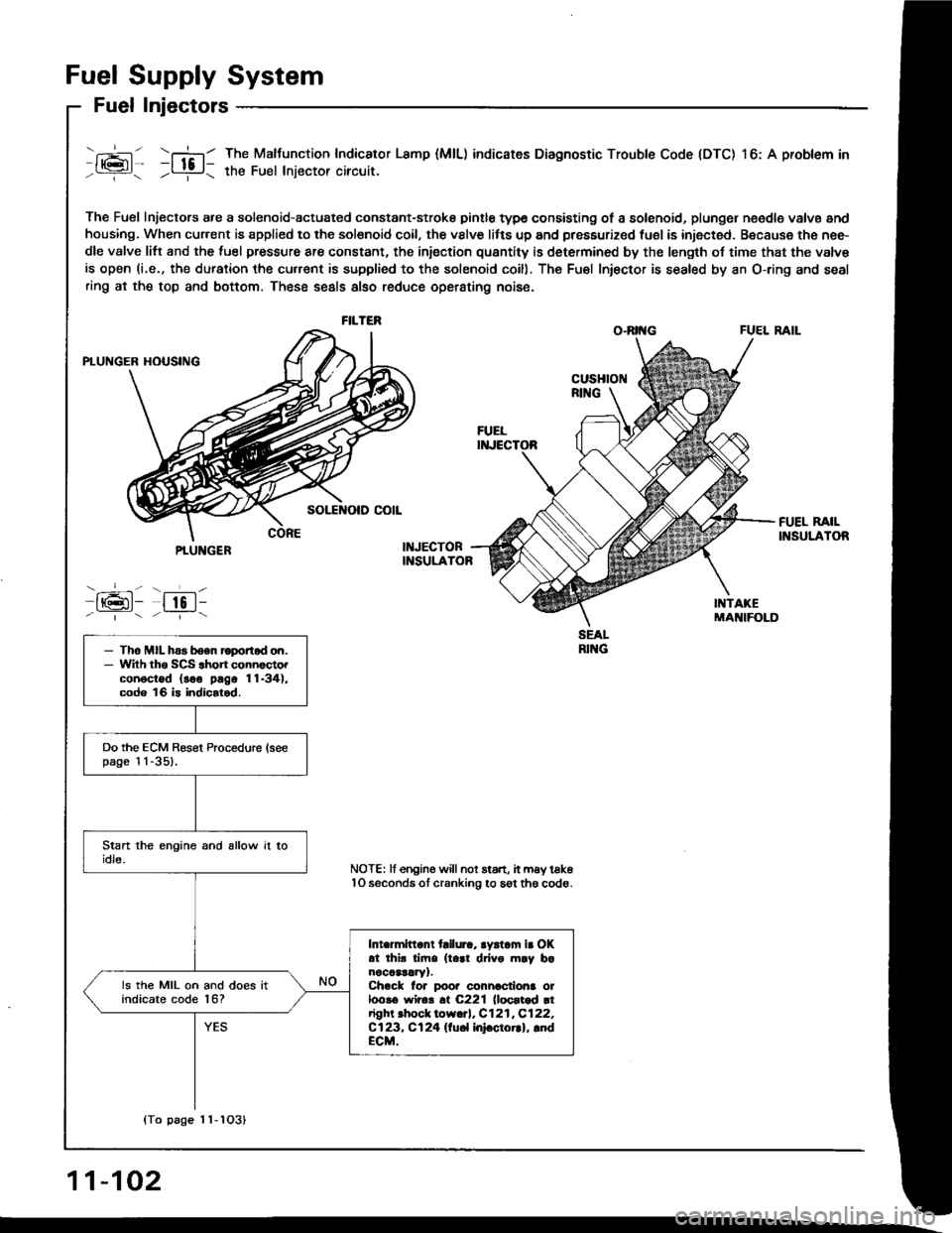
The Fuel Injectors a.e a solenoid-actuated constant-stroke pintle type consisting of a solenoid, plungel n€edle valvs and
housing. When cur.ent is applied to the solsnoid coil, the vslve litts up and pressurized fuel is injected. Because the nee-
dle valve litt and the luel pressure are constant, the iniection quantity is determined by the length of time that the valv€
is open (i.e., the duration the cu.rent is supplied to the solenoid coill. The Fu€l Iniector is sealed by an O-ring and seal
ring at the top and bottom. These seals also reduce operating nois6.
O.RII{G FUEL RAIL
The Malfunction Indicator Lamp (MlL) indicates Diagnostic Trouble Code (DTC) l6: A problem in
the Fuel lniector circuit.
FILTER
PTUNGER
-_-- - ___L-
IrGl- lto l--|.---:_-
- Tho MIL has boen roportod on.- Wilh tho SCS .hon connocto.conoctod (soo pago 11-34),code 16 is indicalod.
Do the ECM Besel Procedure (seepage l l -351.
Intermittant tailura, aystam ir OKat thir tim. (t..1 drivo m.y b.nocaar!ry1.Ch.ck lor poor connactiona ot100!6 wir6!.t C221 (loortod rtright .hock low.rl, C121,C122,Cl23, Cl24 llu6l InFctorrl, lndECM.
ls the MIL on and does itindicate code l6?
NOTE: lf engine willnot start, it may tak6lO seconds ol cranking to sgt th6 code.
{To page 1 1-1O31
11-102
Page 297 of 1413
Filter
Fuel Supply System
Fuel
a Do not smoko while wo*ing on tusl system.
Keop open tlame away ftom your wotk area.a While replaclng th6 tusl liher, be caletul to koop a safodistanc6 betweon battery torminals and any tool3.
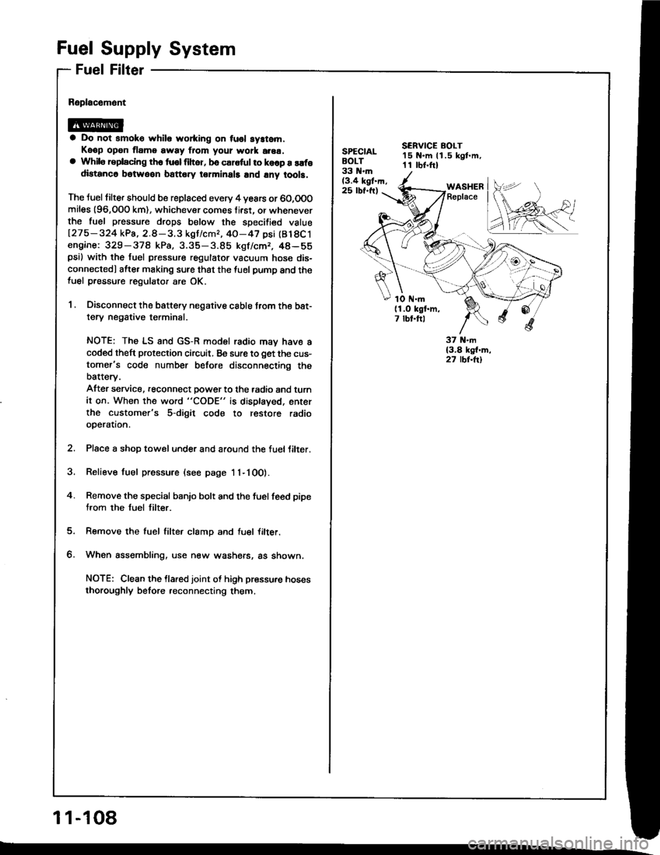
The Juel filter should b€ replaced every 4 years or 60,0O0miles (96,OOO km), whichever comes f irst. or wheneverthe fuel pressure drops below the specilied value
127 5 - 324 kPa, 2.8 - 3. 3 kgJ/cmr, 40-47 psi (Bl 8C 1engine: 329-378 kPa, 3.35-3.85 kgf/cmr, 48-55psi) with the fuel pressure regulator vacuum hose dis-
connectedl afte. making sure that the tuel pump and thefuel pressure regulator are OK.
1 , Disconnect the battery negative cable trom the bat-
tery negative terminal.
NOTE; The LS and GS-R model radio may have acoded theft protection circuit, Be sure to get the cus-
tomer's code number before disconnecting the
batterv.
After service, reconnect power to the tadio and turn
it on. When the word "CODE" is displaved, enter
the customer's 5-digit code to restore radio
operation.
2. Place a shop towel under and around the fueltilter.
3. Relieve fuel pressure (see page 11-100).
4. Remove the special banio bolt and the fuel feed pipe
from the fuel tilter.
Remove the fuel filter clamp and tuel Jilter.
When assembling, use new washers, as shown,
NOTE: Clean the llared joint ot high pressure hoses
thoroughly before reconnecting them,
1 1-108
SPECIALBOLT33 N.m(3.4 kgt.h,25 rbf.ft)
SERVICE BOLT15 N.m ll.5 kgt.m,1 I rbr.ftl
WASHERReplace
1O ttl.m(1.O kgf.m,7 tbt.ftl
Page 393 of 1413
Automatic Transmission
'l4-2
14-3't 4-6
14-8
14-14
14-23
Hvdraulic Flow ...--...... 14-24
Lock-up System ........ 14-38
Eloctrical Systom
Component Location ............,...,................ I 4-45
Circuit Diagram ............. 14-46'Troubleshooting Procedures ........,..........., l4-48
Symptom-to-Component Chart
Electrical System ...... 14-50
Electrical Troubleshooting
Troubleshooting Flowchart .................... 14-52
Lock-uo Control Solenoid Valve A/8
Test .................. --.... \4-82
ReDlacement ,...,...,..,. 14-82
Shift Control Solenoid Vslve A/B
Test .................. ...... 14-83
Reolacement .............. 14-83
Transmission Control Module (TCM)*ReDlacement ........... 14-84
Mainshalt/CountershaJt SDeed Sensors
Reolacement ............. 14-85
Hydraulic Systom
Symptom-to-Component Chart
Hydraulic System
Road Test
Slall Speed
Test ..................
Fluid Level
Checking/Changing
Pressu.e Testing
Transmission
Transmission
Removal ............. ...... 14-99
lllustrated Index
Right Side Cover .................................. 1 4- 1 04
Transmission Housin9 ..................,,....... I 4-1 06
Torque Converter HousingNalve
Body .................. ... 14- 1O8
Right Side Cover
Removal ............. ...... 14-110
Transmission Housing
Removal ............. .-..-. 14-112
Torque Convener HousingNalve Body
Removal ............. ...... 14-114
Valve Caps
Description ................ 14-116
Valve Body
Repair ................ ...-.. 14-117
Valve
Assembly ...........
Oil Pump
Main Valve Body
Disassembly/lnspection/Reassembly
Regulator Valve Body
Disassembly/lnspection/Reassembly
Lock-up Valve Body
Disassembly/lnspection/Reassembly .......
Secondary Valve Body
Disassembly/lnspection/Reassembly .......
Servo Body
Disassembly/lnspection/Reassembly .......
1st-hold Accumulator/Right Side Covet
Oisassembly/lnspection/Reassembly .,..,..
Mainshaft
Disassembly/lnspection/Reassembly -.. -... 1 4- 1 29
lnsDection ................. 14- 130
Countershaft
Disassembly/lnspection/Reassembly ....... 14-132
Disassembly/Reassembly ....................... 1 4-1 33
lnsDection ................. 14-134
One-way Clutch/Parking Gear
Disassembly/lnspection .................... -.. -. 1 4-137
Sub-shaft
Disassembly/lnspection/Reassembly ....... 14-138
Disassemblv/Reassemblv ....................... 1 4-1 39
Sub-shaft Bearings
Replacement ............. l4-140
Clutch
fllustrated lndex ................. -..-...-.......... 14-1 41
Disassembly ,,,.,,........ 14-144
Reassembly .............. 14-146
Torque Converter Housing Bearings
Mainshaft Bearing/Oil Seal
Reolacement ......... 14-1 50
Countershaft Bearing Replacement .......,, 14-1 5l
Transmission Housing Bearings
Mainshsft/Countershaft Bearing
Repfacement ...-..-..14-152
Sub-shaft Bearing Replacement .............. 1 4-1 53
Reve.se ldler Gear
lnstallation ................ 14-154
Parking Brake Stopper
lnspection/Adjustment ..........................'14-'154
Transmission
Reassemblv .............,. .14_156
Toroue Converter/Drive Plate ..,..,............... 1 4- 1 63
Transmission
14-120
14-122
14-123
14-124
14-126
14-124
14-86
14-90
't4-92
14-93
14-94
lnstallation
Cooler Flushing'Shitt Cable
Removal/lnstallation ..............................
Adiustment ...-..-......-. 14-'171*Gearshift Selector
Disassembly/Reassembly .....................,. 1 4-17 2*Shift Indicator Panel
Adjustment -..........-...14-173
Throttle Control Cable
fnspection .......,..,...... 14-17 4
Adjustment .............. 14-176
14-164
14-168
14-'t 7 0
Inspection
Page 398 of 1413
Description
Clutches
The four speed automatic transmission uses hydraulically actuated clutches to engage or disengage the transmission gears.
When clutch pressure is introduced into the clutch drum, the clutch piston is applied. This presses the iriction discs and
steel plates together, locking them so they don't slip. Power is then transmitted through the engaged clutch pack tojts hub-mounted gear.
Likewise, when clutch pressure is bled from the clutch pack. the piston releases the friction discs and steel plates, and
they are {ree to slide past each other while disengaged. This allows the gear to spin independently on its shaft, transmit-
ting no power.
1st ClutchThe l st clutch engages/disengages 1st gear, and is located at the end of the mainshaft, just behind the right side cover.
The 1st clutch is supplied clutch pressure by its oil feed pipe within the mainshaft.
1st-hold clutchThe 1st-hold clutch engages/disengages 1st-hold or I Fosition, and is located at the center ol the sub-shaft. The 1st-
hold clutch is supplied clulch pressure by its oil feed pipe within the sub-shait.
2nd ClutchThe 2nd clutch engages/disengages 2nd gear, and is located at the center of the mainshaft. The 2nd clutch is joined
back-to-back to the 4th clutch. The 2nd clutch is supplied clutch pressure through the mainshaft by a circuit connected
to the regulator valve body.
3rd Clutch
The 3rd clutch engages/disengages 3rd gea.. and is located at the end oJ the countershaft, opposite the right side cover.
The 3rd clutch is supplied clutch pressure by its oil feed pipe within the countershaft,
4th clurch
The 4th clutch engages/disengages 4th gear. as well as reverse gear, and is located at the center of the mainshaft.
The 4th clutch is joined back-to-back to the 2nd clutch. The 4th clutch is supplied clutch pressure by its oil feed pipe
within the mainshalt.
One-way Clutch
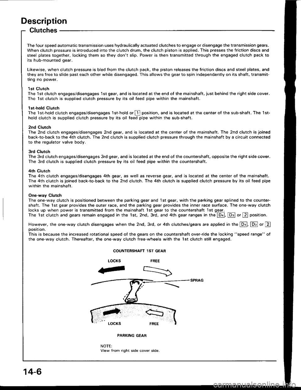
The one-way clutch is posjtioned between the parking gear and 1st gear. with the parking gear splined to the counter-
shaft. The 1st gear provides the outer race, and the parking gear provides the inner race surface. The one-way clutch
locks up when power is transmitted from the mainshaft 1st gear to the countershaft lst ggel _The 1st clutch and gears remain engaged in the 1st. 2nd. 3rd, and 4th gear ranges in the @, E or E position.
However, the one-way clutch disengages when the 2nd. 3rd, or 4th clutches/gears are applied in the E, lD.l o, Eoosttton.
This is because the increased rotational speed of the gears on the countershaft over-ride the locking "speed range" of
the one-way clutch. Thereafter, the one-way clutch free-wheels with the lst clutch still engaged.
COUNTERSHAFT 1ST GEAR
FREE
:>
LOCKS
aF
NOTE:View trom right side cover side.
14-6
Page 424 of 1413
Description
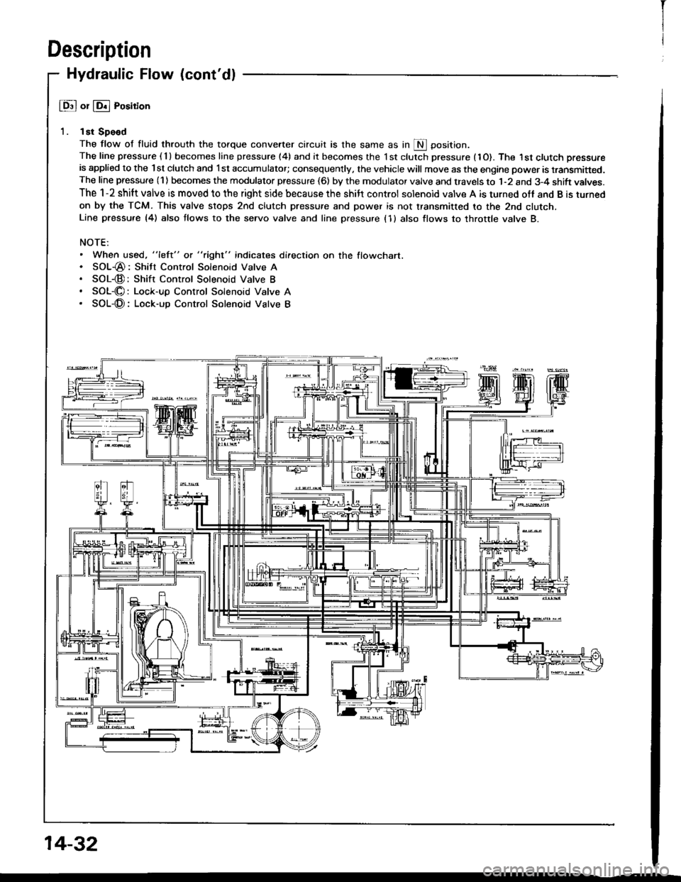
Hydraulic Flow (cont'dl
@ or @ Position
1. lst Spe€d
The flow of fluid throuth the torque convener circuit is the same as in S Oosition.The line pressure ( 1 ) becomes line pressure (4) and it becomes the 1 st clutch pressure (1O). The I st ctutch pressure
is applied to the lst clutch and l st accumulator; consequently, the vehicle will move as the engine power is transmitted.The line pressure (1) becomes the modulator pressure (6) by the modulator valve and travels to 1-2 and 3-4 shift valves.
The 1-2 shift valve is moved to the right side because the shilt control solenoid valve A is turned off and B is turned
on by the TCM. This valve stops 2nd clutch pressure and power is not transmitted to the 2nd clutcn.Line pressu.e {4) also tlows to the seryo valve and line pressure (1 } also flows to throttle valve B.
NOTE:. When used, "left" or "right" indicates direction on the flowchart.. SOL-@: Shitt Control Solenoid Valve A. SOL-@:Shift Control Solenoid Valve B. SOL-O: Lock-up Control Solenoid Valve A. SOL-@: Lock-up Control Solenoid Valve B
14-32
I
Page 428 of 1413
Description
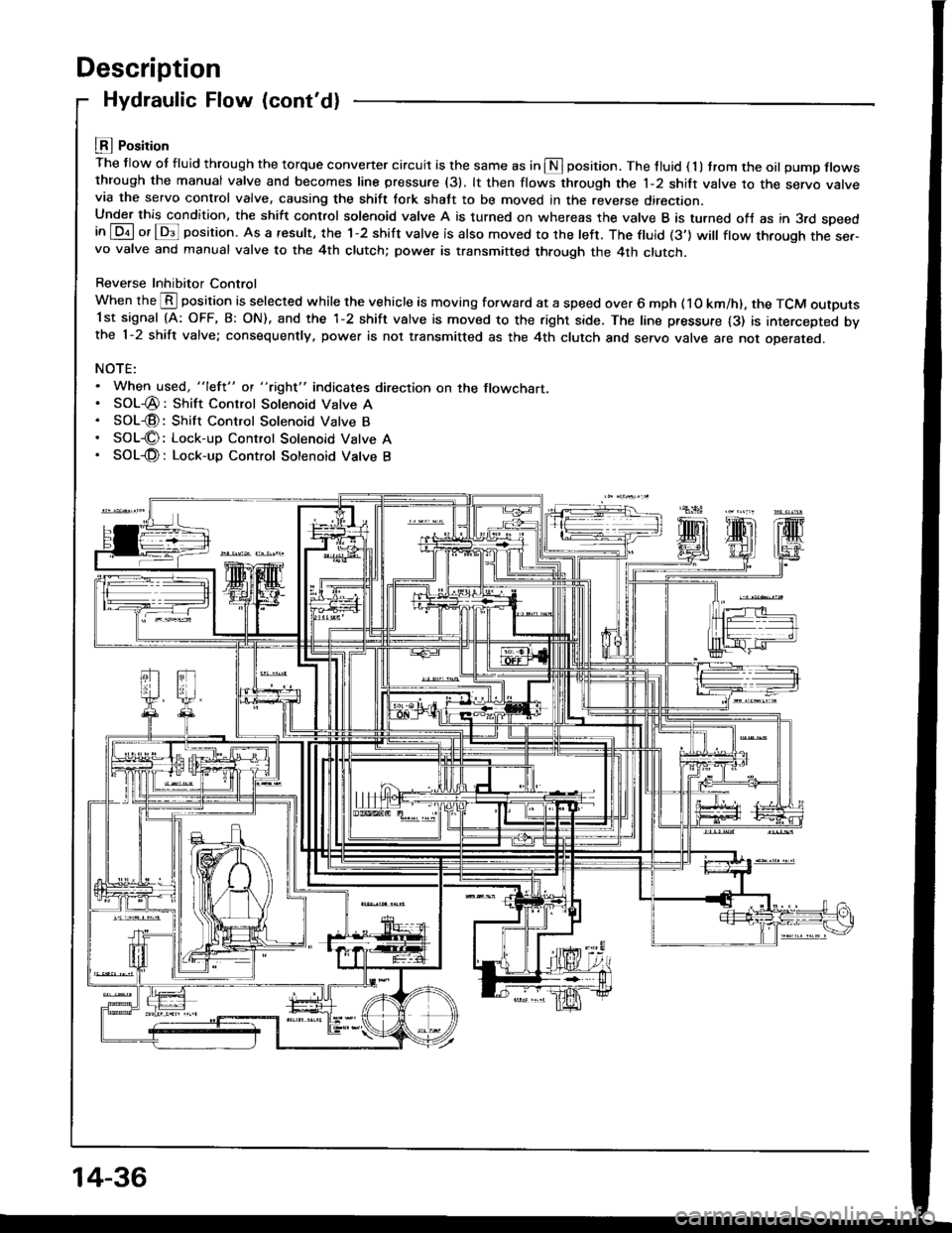
Hydraulic Flow (cont'd)
LEI Position
The flow ot fluid through the torque convener circuit is the same as in S position. The tluid ( 1 ) trom the oil pump flowsthrough the manual valve and becomes line pressure (31. lt then flows through the 1-2 shift valve to the servo varvevia the servo control valve, causing the shift tork shatt to be moved in the reverse direction.Under this condition, the shift control solenoid valve A is turned on whereas the valve B is turned ofJ as in 3rd speedin [Dil or lDs]l position. As a result, the 1-2 shift valve is also moved to the left. The ftuid (3'] will ftow through the ser-vo valve and manual valve to the 4th clutch; power is transmitted through the 4th clutch.
Reverse Inhibitor Control
When the @ position is selected while the vehicle is moving forward at a speed over 6 mph ( 1O km/h). the TCM outputs1st signal (A: OFF, B: ON), and the 1-2 shift valve is moved to the right side. The line pressure {3) is intercepted bvthe 1-2 shift valve; consequently, power is not transmitted as the 4th clutch and servo valve are not oDerareo.
NOTE:. When used, "lefl" ot "tight" indicates direction on the flowchart.. SOL-@: Shift Control Solenoid Valve A. SOL€: Shift Control Solenoid Valve B. SOL€: Lock-up Control Solenoid Vatve A. SOL-@: Lock-up Control Sotenoid Vatve B
14-36
Page 429 of 1413
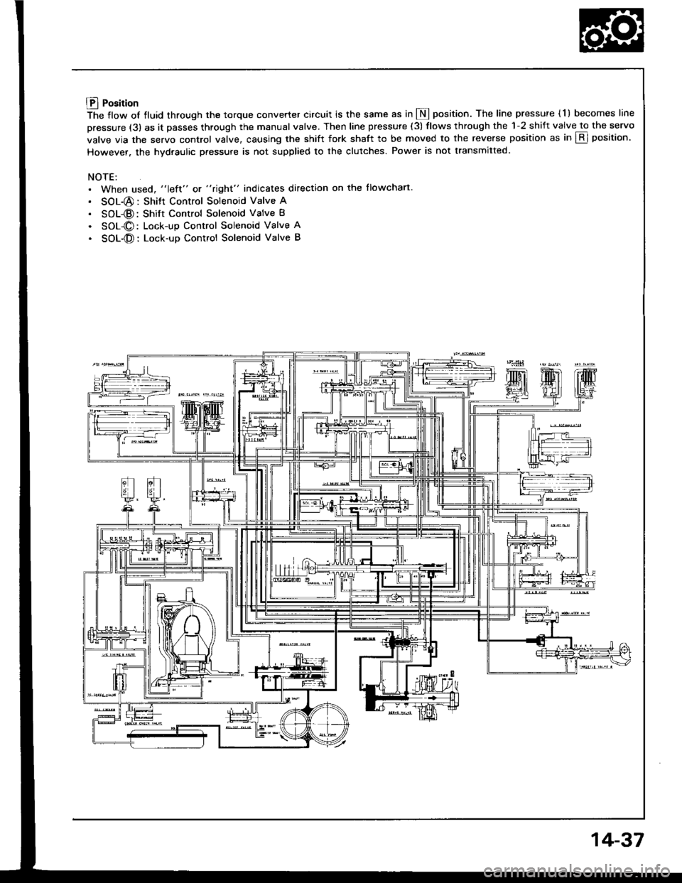
Lll Position
The flow of fluid through the torque converter circuit is the same as in I position. The line pressure ( l ) becomes line
pressure (3) as it passes through the manual valve. Then line pressure (3) flows through the 1-2 shift valve to the servo
valve via the servo control valve. causing the shift fork shaft to be moved to the reverse position as in E position.
However. the hydraulic pressure is not supplied to the clutches. Power is not transmitted.
NOTE:. When used, "left" or "right" indicates direction on the flowchart.
. SOL-@: Shitt Control Solenoid Valve A
. SOL-@: Shift Control Solenoid Valve B
. SOL-O: Lock-up Control Solenoid Valve A
. SOL-O: Lock-up Control Solenoid Valve B
14-37
Page 438 of 1413
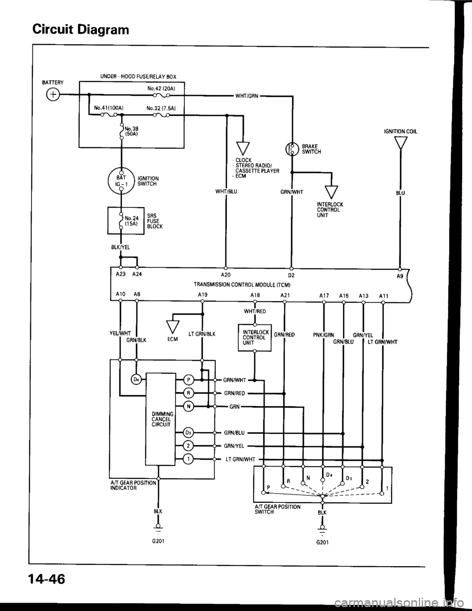
Circuit Diagram
tGNtTtoN c0 -
V
I
I
IBLU
UNDER HOOD FUSE/RELAY 80X
AN GEAR POSITIONINDICATOR
BLK
T
G201
No.411100A) No.32 (7.5A)
423 424 A20 D2
TRANSMISSION CONTROL MOOUI.E {TCM)
Ar0 A8 A19 A18 A21 A17 A15 A13 Alt
I A' V A-" t2
| *---i. t,,,:----<) l1
8LK
{
G201
14-46
A/'I GEAR POSIIIONswtrcH
Page 476 of 1413
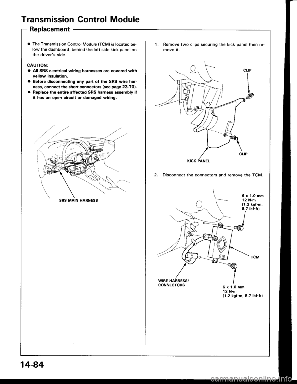
Transmission Control Module
Replacement
I The Transmission Control Module (TCMI is located be-
low the dashboard, behind the lelt side kick panel on
the driver's side.
CAUTION:
a All SRS electrical wiring hahesses are covered withyellow insulation.
a Betore disconnecting any pan ot the SRS wile har-
ness. connect the short connectors lsee page 23-7O).
a Replace the entir6 affected SRS harness ass€mbly if
it has an open circuit or damaged wiring.
1. Remove two clips securing the kick panel then
move it.
2. Disconnect the connectors and remove the TCM.
6 x 1.0 mm12 N'm{1.2 kgf.m,8.7 tbf.Itl
WIRE HARNESS/CONNECTORS6 x 1.0 mm12 N.m(1.2 kgf.m, 8.7 lbt.ftl
KICK PANEL
SRS MAIN HARNESS
14-84
Page 560 of 1413
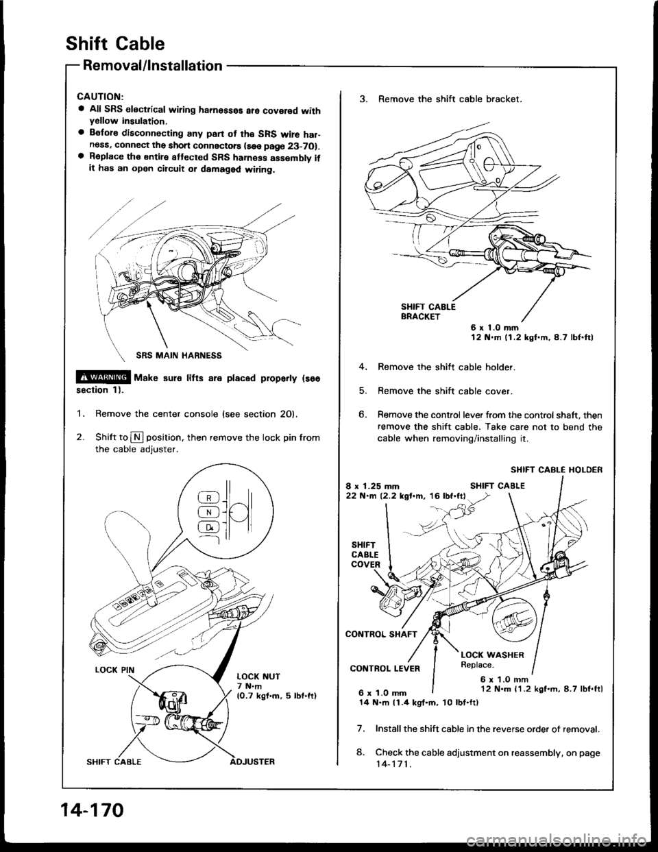
shift cable
Removal/lnstallation
a All SRS electrical wiring hamosses are covor€d withyellow insulation.
a Before disconnecting any pan ot th€ SRS wire har-noss, connect the short connectorc (soe page 23-7O1.a Roplace th€ entiro attect€d SRS haness assembly itit has an open circuit ot damaged wi.ing.
@@[ uar" sul€ litts are placed proparty {so6
section 1).
1. Remove the center console {see section 20).
2. Shift to N position. then remove the lock pin from
the cable adjuster.
@J^ll
AJUI[qJ ]l tl---l
LOCK NUT7 N.m(O.7 kgf.m, 5 lbf.ft)
14-170
3. Remove the shift cable bracket.
6x1.0mm12 N.m 11.2 kgf.m,4.7 lbf.ftl
4. Remove the shitt cable holder.
5. Remove the shift cable cover.
6. Remove the control lever from the control shaft, then
remove the shift cable. Take care not to bend the
cable when removing/installing it.
SHIFT CABLE I{OLDER
Install the shift cable in the reverse orde. of removal.
Check the cable adjustment on reassembly, on page
14-171.
7.
8.
12 N.m 11.2 kgf.rh, 8.7 lbf.ftl
14 N.m 11.4 kgl.m, 10lbt.ft)