evap HONDA INTEGRA 1994 4.G Owner's Manual
[x] Cancel search | Manufacturer: HONDA, Model Year: 1994, Model line: INTEGRA, Model: HONDA INTEGRA 1994 4.GPages: 1413, PDF Size: 37.94 MB
Page 303 of 1413
Fuel Supply System
Fuel Tank
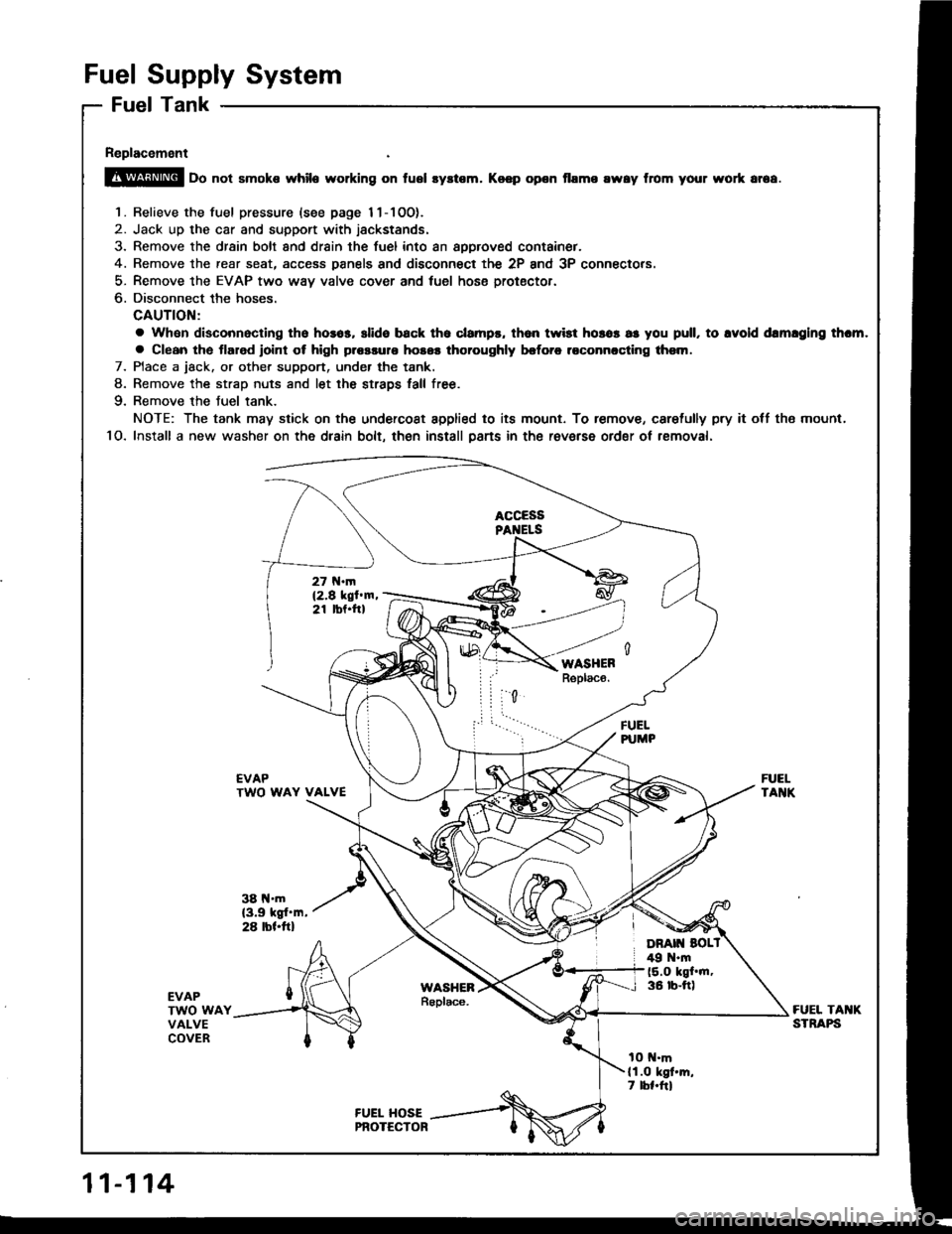
Replacement
@ oo not smoke while working on fusl syltem. Koep opon flame rway from your wort ar6a.
1. Relieve the fuel pressure {see page 11-1OO).
2. Jack up the car and support with jackstands.
3. Remove the drsin bolt and drain the fuel into an approved container.
4. Remove the rear seat, access Danels and disconnect the 2P and 3P connectors.
5- Remove the EVAP two way valve cover and tuel hose protector.
6. Disconnect the hoses.
CAUTION:
a Whan disconnacling tho hosos, slide back tho clampr, th6n twist horos as you pull, to lvold drmlglng thcm.
a Clean the tlarod roint ot high plossulo hosos thoroughly brforc roconnccling thsm.
7. Place a jack. or other support, under the tank.
8. Remove the strao nuts and let the straDs tall free.
9. Remove the Juel tank.
NOTE: The tank may stick on the undercoat applied to its mount. To remove, caretully pry it off tho mount,
1O. Install a new washer on the dlain bolt, then install psns in the raverse ordgr ot rsmoval.
FUELPUMP
EVAPTWO WAY VALVE
38 l{.m(3.9 kgt'm,28 rbl.ftl
FUELTANK
EVAPTWO WAYVALVECOVER
FUEL TAI{KSTRAPS
tO t{.mll.O kgt'm,7 lbl.frl
11-114
Page 309 of 1413
lntake Air System
Throttle Body
Description
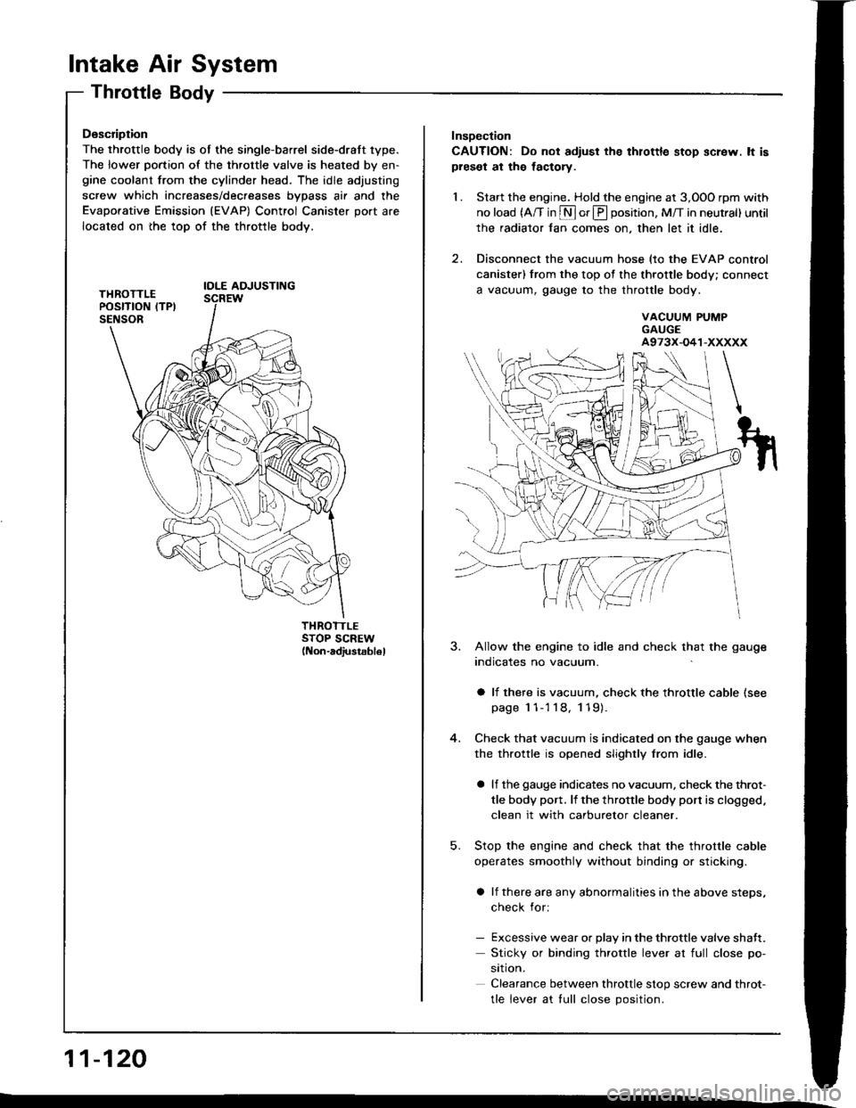
The throttle body is ot the single-barrel side-draft 1ype.
The lower portion of the throttle valve is heated by en-gine coolant from the cylinder head. The idle adjusting
screw which increases/dec.eases bvDass air and the
Evaporative Emission (EVAP) Control Canister port are
located on the top of the throttle body.
IOLE AOJUSTING
THROTTLESTOP SCREW(Non-adiustsb16l
11-120
Insoection
CAUTION: Do not adiust the thlottle stop screw. lt ispreset at the lactory.
1. Start the engine. Hold the engine at 3,OOO rpm with
no load (A/T in S or E position, M/T in neutral) until
the radiator fan comes on, then let it idle.
2. Disconnect the vacuum hose (to the EVAP control
canister) from the top of the throttle body; connect
a vacuum, gauge to the throttle body.
VACUUM PUMPGAUGEA973X-O41-XXXXX
5.
3. Allow the engine to idle and check that the gauge
indicates no vacuum.
a li there is vacuum, check the throttle cable (see
page 1 1-'l 18, 119).
Check that vacuum is indicated on the gauge when
the throttle is opened slightly from idle.
a lf the gauge indicates no vacuum, check the throt-
tle body port. lf the throttle body port is clogged.
clean it with carburetor cleaner.
Stop the engine and check that the throttle cable
operates smoothly without binding or sticking.
a lf there are any abnormalities in the above steps,
check for:
- Excessive wear or Dlav in the throttle valve shaft.
Sticky or binding throttle lever at full close po-
srtron.
Clearance between throttle stop screw and throt-
tle lever at tull close Dosition.
Page 318 of 1413
Emission Control System
System Troubleshooting Guide
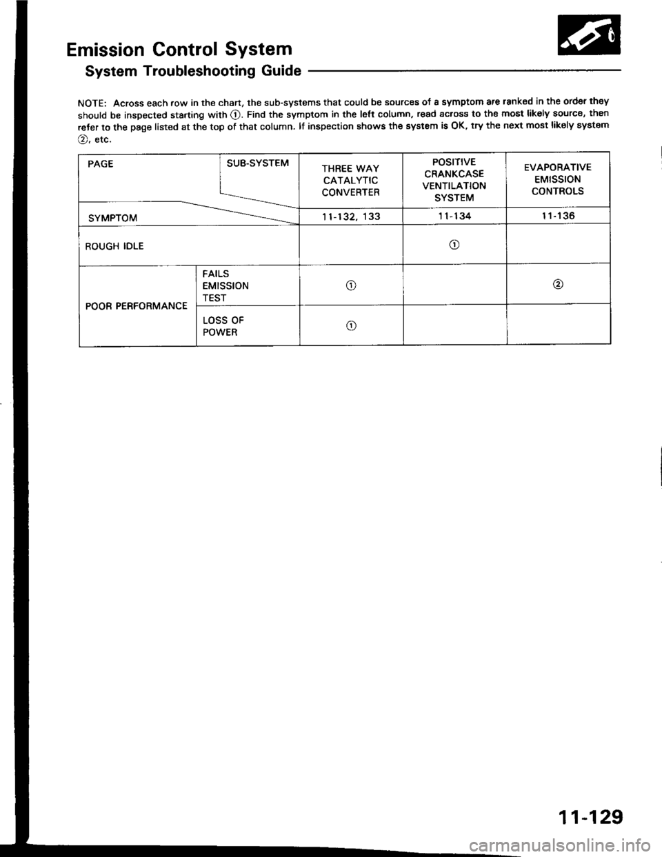
NOTE: Across each row in the chart, the sub-systems that could be sources of a symptom are lanked in the ord€r they
should be inspected starting with O. Find the symptom in the lett column, read across to the most likely source, then
reJer to the page list€d at the top of that column. lf inspection shows the system is OK, try the next most likely system
@, etc.
PAGE
SYMPTOM
SUB.SYSTEMTHREE WAY
CATALYTIC
CONVERTER
POSITIVE
CRANKCASE
VENTILATION
SYSTEM
EVAPORATIVE
EMtSSTON
CONTROLS
11-132, 1331 1- 13411tJo
ROUGH IDLEo
POOR PERFORMANCE
FAILS
EMISStON
TEST
o@
LOSS OF
POWERo
11-129
Page 319 of 1413
Emission Control System
SystemDescription
The emission control system includes a Three Way Cata-
lytic Convener (TWC), Positive Crankcase Ventilation(PCV) system and Evaporstive Emission {EVAP) Contfol
syst€m. The emission control system is designed to meet
federsl and stats emission standards.
Tailpipe Emission
Inspection
f!fifil oo nor amoro ou]rng rnr! Foacqurr. ^!op
any open flame away from yout wotk atca.
Start the engine. Hold the engine at 3,OOO rpm with
no load (A/T in @ or@ position, M/T in neutral) until
the radiator fan comes on, then let it idle,
Connect a tachometer.
Check and adiust the idle speed, if necessary (sss
page 1 1-95).
Warm up and calibrate the CO meter according to
the meter manutacturer's inst.uctions.
Check idle CO with the headlights, hester blower,
rear window defogger, cooling fan, and air condition-
er otf.
NOTE: (Canada) Pull the parking br8ke lever up.
Stan the engine, then check that the headlights are
off.
CO meter should indicate 0.1 maximum.
11-130
Page 324 of 1413
A.
Evaporative Emission (EVAPI Controls
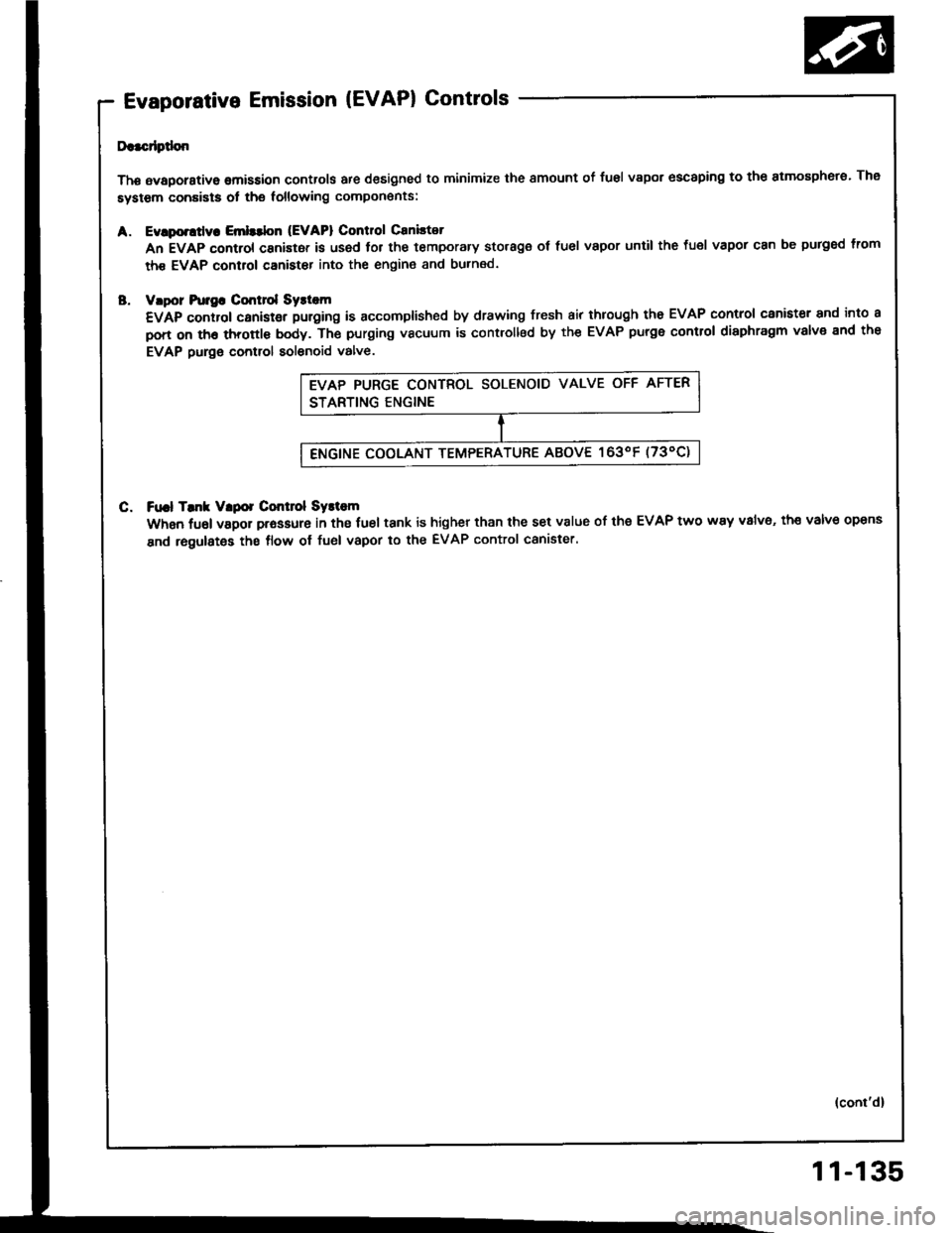
Da.cdptlon
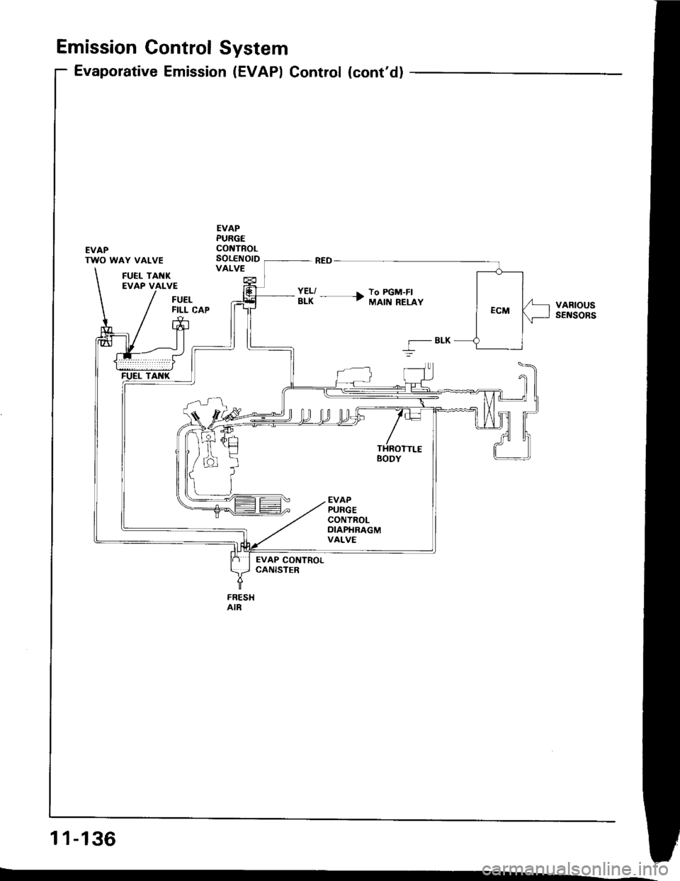
Thg avaporstive omission controls are designed to minimize the smount of fusl vapor escaping to the atmosphero. The
system conaists ot the following compon€nts:
Evlporttly. Emlttbn (EVAPI Control Caniltot
An EVAP control canistor is used lor the temporary storage ot fuel vapor until the fuel vapor can be purged lrom
th€ EVAP control canister into the engin€ and burned.
vlpor hr]gG Cmt]ol Syst m
€VAp control canistgr puroing is accomplished by drawing fresh air through tho EVAP control canister and into a
pon on th6 throttl€ body. Th€ purging vacuum is controllsd by the EVAP purge control diaphragm valve end the
EVAP purge control solenoid valve.
C. Ft|.l Tmk Vlpor Control Systom
When fuel vapor prassure in the fuel tank is higher than the set v8lue of the EVAP two way v8lv6, th€ valve opens
and regulates the flow ol fuel vapor to the EVAP control canister.
(cont'd)
11-135
Page 325 of 1413
Emission Gontrol System
Evaporative Emission (EVAPI Control (cont'd)
EVAPTWO WAY VALVE
EVAPPURGECONTROLSOLENOIDVALVEFUEL TANKEVAP VALVE
FUELFILL CAPVARIOUSsEt{soRs
BLK
5
EVAP CONTROLCANISTEB
FRESHAIR
11-136
Page 326 of 1413
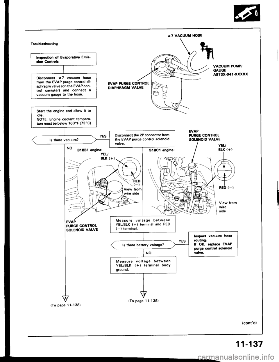
#7 VACUUM HOSE
Troublclhooting
VACUUM PUMP/GAUGEA973X-O41-XXXXX
EVAP PTJBGE COI{TROLDIAPHRAGM VALVE
EVAPPUBGE CONTROL
Bl8Bl .noin.:YEL/BLK I+I
(-t
wirg aide
--\
EVAPR'RGE COI{TROLSOLENOID VALVE
(cont'd)
VALVE
YEL/BLK (+I
Disconn€ct #7 vacuum hose
trom the EVAP putgo control di'
aph.agm valve lon the EVAPcon-
t.ol canistor) and connoct a
vacuum gauge to tho hose.
Stsrt the €ngine and allow it toidls.NOTE: Engine coolant tempera-
ture must be b€low 163oF (73ocl
Oisconnect the 2P connegtor trom
the EVAP purge control solenoid
Mea suro voltago betw€enYEL/BLK {+) terminsl 6nd RED
l-) terminal.
Inapact vacuum hoa€ror.ring.l| OK, toolrc. EVAPpurgo conttol solenoidls ther6 battery voltage?
Moasule voltage botweenYEL/BLK {+) terminal bodYground.
(To pa96 1 1- 138)
(To page 1 'l -139)
11-137
Page 327 of 1413
(From page 1 1-137)
lTo page 1 1-'l39)
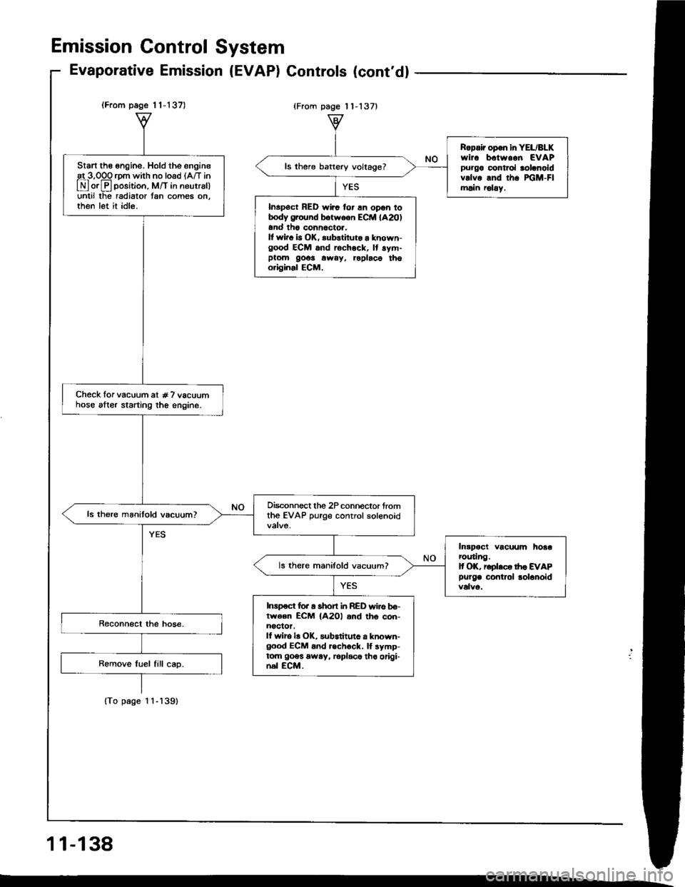
Start the engine. Hold the engineat 3,OOO rom with no load lA/T in
E orE position, M/T in neutrsl)unlil lhe radiator tan comes on.then let it idle.
Check lor vacuum at # 7 vacuumhose alter starting the engine.
Oisconnect the 2P connoctor fromthe EVAP purge control solenoid
Intpoct vacuum hoaarcuting.It OK, reolrco tr|c EVAP
Purge contlol lolanoid
ls there manifold vacuum?
Inrpoct for a short i|t RED wire bo-lwoen ECM {A2Ol and th6 con-noclor.ll wiro la OK, substituto a known-good ECM 6nd .echock. lf symp-tom goes away, loplace tho origi-nal ECM.
Ropair opon in YEL/BLKwirc b.tw..n EVAPpurgo control rolanoidvrlvo and th. xiM-Flmlin r6lay.
ls there baftery voltage?
Inspoct RED wirc for 6n opon totrody g.ound botween ECM lA20)and th6 conn6ctor.It wir. b OK, substiluto a known-good ECM and rochock, It sym-ptom 9o6s away, roplaco thooriginal ECM,
Emission Gontrol System
Evaporative Emission (EVAP) Gontrols (cont'd)
{From page 11-137}
11-138
Page 328 of 1413
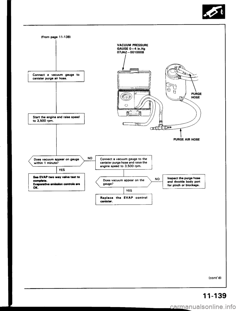
(F.om pdge 1l-138)
Connoct a vlcuum gaugo tocaniator purg! lir ho!o.
Stsn tho onginc lnd rai!. spo€dto 3,50O rpm.
Connect a vacuum gauge to thecsnister puag6 hos6 and raise thesngin€ spe€d to 3,500 rpm.
Do€a vocuum opp€ar on gougo
within 'l minuto?
Saa EVAP tso {ay vdv. t.!t ioconrDbta.Evapoardva ambdon coartaoL |.|ox.
Inapoct tha purga hosoand drronl. body potl
for pinch or blocklga.
VACUUM PRESSUREGAUGE O-4 In.HgoTJAZ-OOIOOOB
PURGE AIR HOSE
(cont'd)
11-139
Page 329 of 1413
Emission Control System
Evaporative Emission Controls
(cont'dl
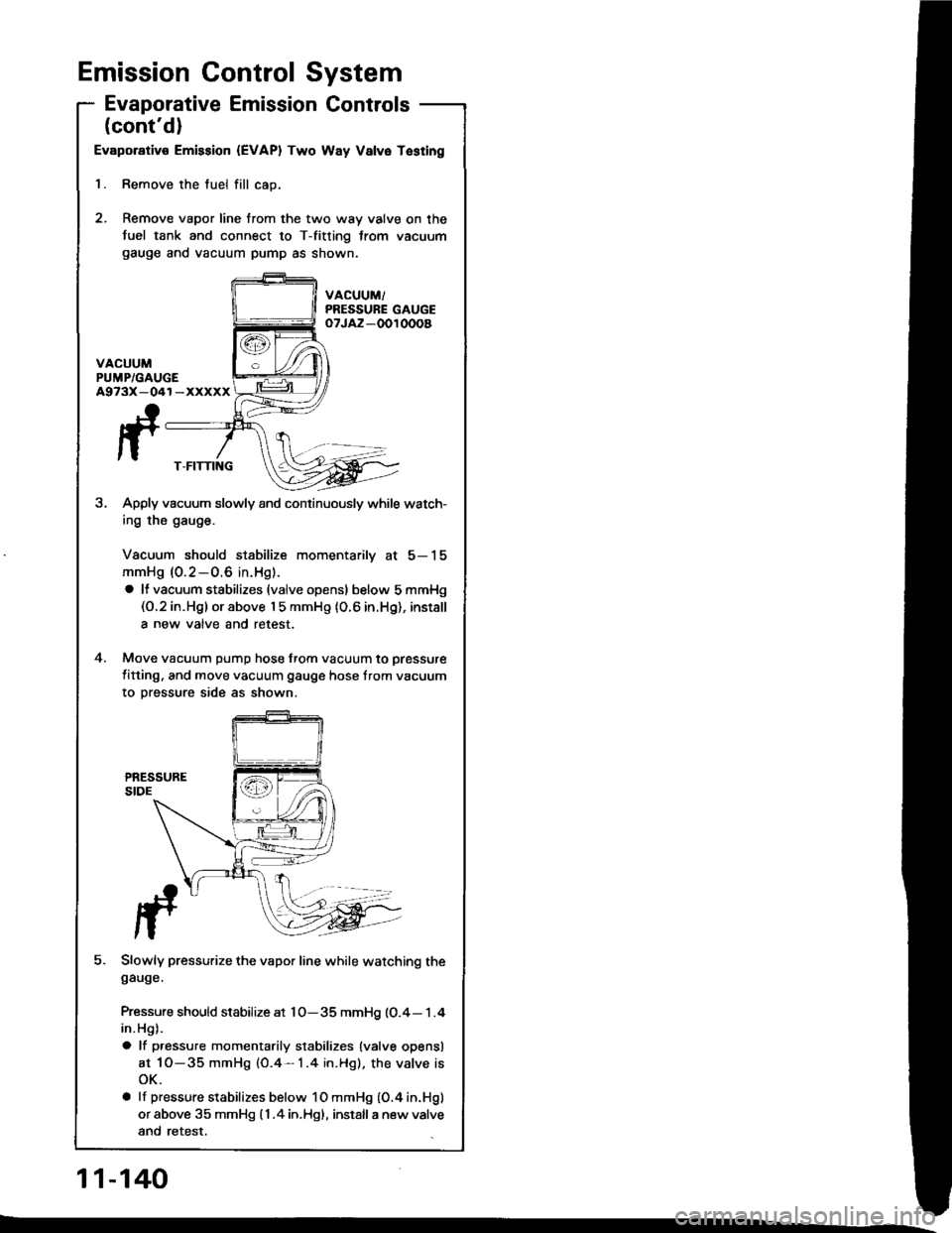
Evaporativ€ Emission {EVAPI Two Way Valvo Tasting
l. Remove the tuel fill cao.
2. Remove vapor line trom the two way valve on the
fuel tank and connect to T-fitting trom vacuum
gauge ano vacuum pump as snown.
VACUUM/PRESSURE GAUGEoTJAZ-OOI OOOa
A973X-041-XXXXX
fT-FITTING
Apply vacuum slowly and continuously while watch-
ing the gauge.
Vacuum should stabilize momentarilv at 5-15
mmHg (0.2-0.6 in. Hg).
a It vacuum stabilizes (valve opensl below5mmHg(O.2 in.Hg) or above I 5 mmHg (O.6 in.Hg), install
a new valve and retest.
Move vacuum pump hose from vacuum to pressure
titting, and move vacuum gauge hose trom vacuum
to oressure side as shown.
Pressure should stabilize at 1O-35 mmHg (0.4- 1 .4
in. Hg).
a lf p.essure momentarily stabilizes {valve opensl
at 1O-35 mmHg (O.4- 1.4 in.Hg), the valve is
oK.
a lf pressure stabilizes below 10 mmHg {O.4 in.Hg)
or above 35 mmHg (1 .4 in.Hgl, install a new valve
and retest.
4.
J-.
fF . -,-/ asr^:
,T 4?e
Slowly pressurize the vapor line while watching thegauge.
11-140