evap HONDA INTEGRA 1994 4.G User Guide
[x] Cancel search | Manufacturer: HONDA, Model Year: 1994, Model line: INTEGRA, Model: HONDA INTEGRA 1994 4.GPages: 1413, PDF Size: 37.94 MB
Page 197 of 1413
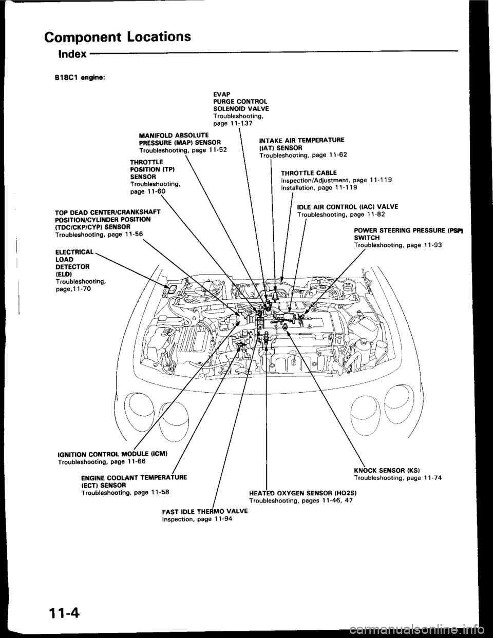
Component Locations
lndex
B18Cl ongino:
THROTTLEPOSITION (TP}
SENSOR
MANIFOLD AESOLUTEPRESSURE (MAPI SENSOR
Troubleshooting, page 1 1-52
EVAPPURGE CONTROLSOLEiIOID VALVETroubleshooting,page 11-137
VALVE
INTAKE AIR TEMPERATURE
IIAT) SENSORpage 11-62
THROTTLE CABLEInspection/Adiustment, page 'l 1-1 19
lnstallation, page 1 1-1 19
IOLE AIF CONTROL (IACI VALVETroubleshooting. page 1 1 -82
Troubleshooting,page 1 1-6O
TOP DEAD CENTER/CRANKSHAFTPOSITION/CYLINDER POSITION
{TDC/CKP/CYPI SEI{SORTroubl€shooting. Page 1 1 -56POWER STEERING PRESSURE (PS'I
swtTcHTroubleshooting, page 1 1-93ELECTRICALLOADDETECTORIELD}Troubleshooting,page.1 1-70
IGNITION CONTNOL MODULE OCMI
Troubleshooting, Psge 1'l-66
ENGIT{E COOLANT TEMPERA
{ECT} SEI{SORTroubleshooting, Pag€ 1 1-58
sElrlsoR tKslTroubfeshooting, page 1 1 -7 4
HEATED OXYGEN SENSOR (HO2S}
Troubleshooting, pages 11-46, 47
FAST IDLEInspection, page 1 'l -94
11-4
Page 199 of 1413
![HONDA INTEGRA 1994 4.G User Guide System Description
Index
FUEL FILTERReplacement, page 11- l OB
FUEL II{JECTORSTroubleshooting, page 1 1-102Replacemont, page 1 1-105
FUEL FEED PIPE
FUEL GAUGE SE]IIDING U]{ITTgsting, s€ction 23
FU� HONDA INTEGRA 1994 4.G User Guide System Description
Index
FUEL FILTERReplacement, page 11- l OB
FUEL II{JECTORSTroubleshooting, page 1 1-102Replacemont, page 1 1-105
FUEL FEED PIPE
FUEL GAUGE SE]IIDING U]{ITTgsting, s€ction 23
FU�](/img/13/6067/w960_6067-198.png)
System Description
Index
FUEL FILTERReplacement, page 11- l OB
FUEL II{JECTORSTroubleshooting, page 1 1-102Replacemont, page 1 1-105
FUEL FEED PIPE
FUEL GAUGE SE]IIDING U]{ITTgsting, s€ction 23
FU€L
FUEL PUMPT€sting. page 11- 1 10Roplscam€nt. page 11-l 10
FUEL FIIL CAP
FUEL TA KR6placomont,page l1-114
EVAFORATIVE EMISSIONIEVAP} TWO WAY VALVETesting, pag€ 11-140
EVAPORATIVEEMTSStOt{{EVAP} PURGECONTROL DIAPHNAGMVALVETroubleshooting, page'l 1-137
PNESSURE REGUIATORTesting, page 11-106Roplac€m€nt, page 1 1-107
FUEL RAIL
EVAFORATIVC EMISSION(EVAPI COI{TROL CANISTERTroubl6shooting. pag6 1 1-'l 37
FUEL VAFON APE
11-6
Page 200 of 1413
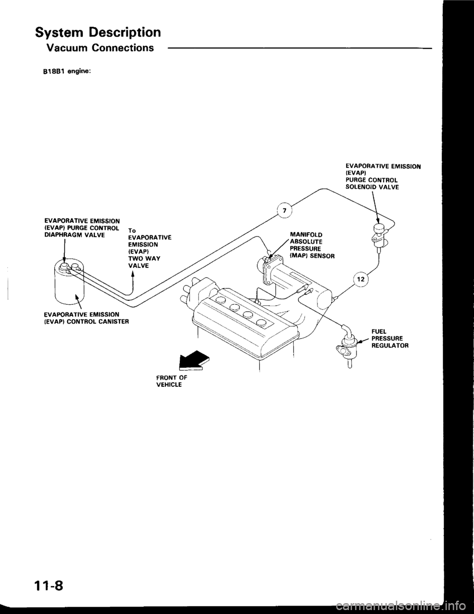
System Description
Vacuum Connections
81881 engin€:
EVAPORATIVE EMISSION(EVAP} PURGE CONTROLDIAPHRAGM VALVE
EVAPORATIVE EMISSIOT{(EVAPI
PURGE CONTROLSOLENOID VALVE
ToEVAPORATIVEEMtSSTON{EVAP}TWO WAYVALVE
EVAPORATIVE EMISSIONIEVAP) CONTROI- CANISTER
FRONT OFVEHICLE
11-8
Page 201 of 1413
ENGINECOOLANT
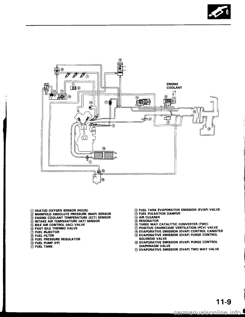
@ FUEL TAI{K EVAPORATIVE EMISSION (EVAP} VALVE
G) FUEL PULSATION DAMPER
@ AIR CLEANER
@) RESONATOR
@ THREE WAY CATALYTIC CONVEnTER (TWC)
o POS|TIVE CRANKCASE VEITITILAT|ON IPCV) VALVE
@ EVAPOBATIVE EMISSION IEVAP) COI{TROL CANISIER
@ EvApoRATrvE EMrssroN IEVAP) PURGE coNTRoL
SOLENOID VALVE
@ EVAPORATTVE EMISSION (EVAP) PURGE CONTROL
DIAPHRAGM VALVE(iD EVAPORATIVE EMISSION (EVAPI TWO WAY VALVE
|l
U]
HEATED OXYGEI{ SEI{SOF (HO2S}
MANIFOI.D ABSOLUTE PRESSURE (MAP) SEI{SONENGINE COOLANT TEMPERATURE IECT} SENSORINTAKE AIR TEMPERATURE IIAT} SEI'ISORIDLE AIR CONTROL IIAC) VALVEFAST IDLE THERMO VALVEFUEL II{JECTORFUEL FILTERFUEL PRESSURE REGULATONFUEL PUMP IFP)FUEL TAI{K
11-9
Page 202 of 1413
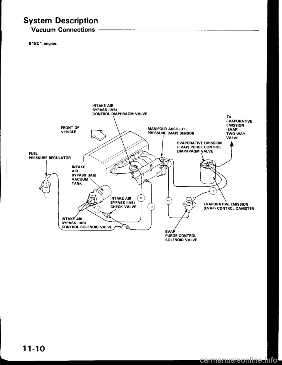
System Description
Vacuum Connections
818C1 engine:
INTAKEAIRBYPASS IIAB}VACUUMTANK
INTAKE AIRSYPASS IIAB}CONTROL DIAPHRAGM VAI-VE
MANIFOLO ABSOLUTEPRESSURE {MAP) SENSOR
toEVAPORATIVEEMISStONIEVAPITWO WAYVALVE
EVAPORATIVE EMISSION{EVAP) PURGE CONTROLDIAPHRAGM VALVE
EVAPORATIVE EMISSIONIEVAPI CONTROL CANISTER
INTAKE AIRBYPASS IIABICONTROL SOLENOID VALVE
PURGE CONTROLSOLENOID VALVE
11-10
Page 203 of 1413
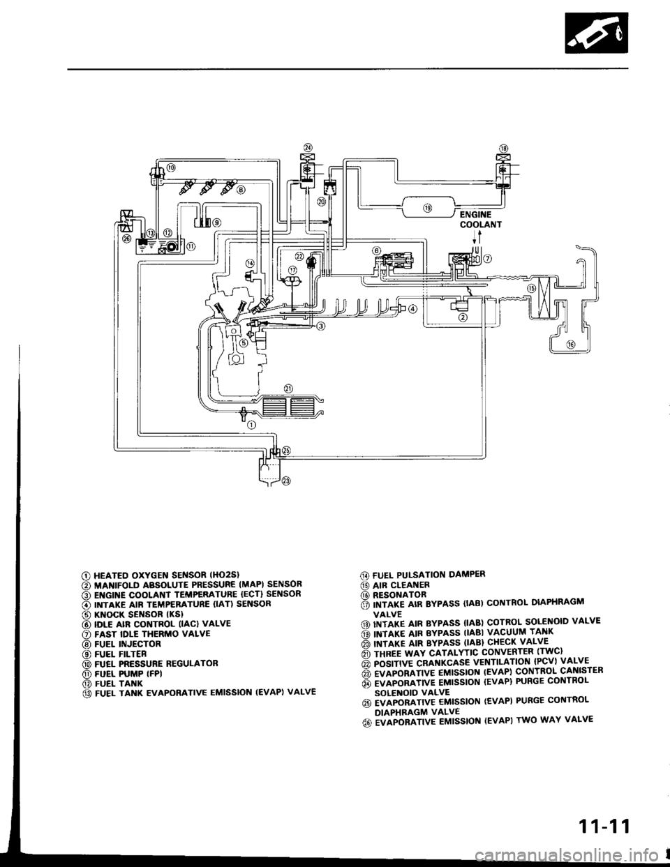
G) FUEL PUI-SATION DAMPER
@ AIR CLEANER(D RESONATOR6 imrlre arR Bypass (tAB) coNTRoL DIAPHRAGM
VALVE(D) IITITP IIN BYPASS {IAB) COTROL SOLENOID VALVE
ds) INTIXT AIR EYPASS TIABI VACUUM TANK
rio'l rnrarg ltn BYPASS (lABl cHEcK vALvE
6 rsnee wav cATALYTtc coNvERTER lrwc)
6 posrnve cRAf{KcAsE vENTILATIoN {Pcv) vALVE
6 evlponlrtve EMtsstot{ tEvAPl coNTBoL cANlsrER
6 evlponltvE EMtssloN {EvAP} PURGE coNTRoL
SOLENOID VALVE6i EVAPORATIV€ EMISSION (EVAPI PURGE CONTROL
DIAPHRAGM VALVE
6o ivlpoalrtve Eutsstof{ IEVAPI rwo wAY vALvE
c) HEATED OXYGEN SENSOR lHO2Sl
€) MANIFOLD ABSOLUTE PRESSURE IMAPI SENSOB
O EI{GINE COOLANT TEMPERATURE {ECT} SENSOR
€) INTAKE AIR TEMPERATURE {IAT) SENSOR
@ KNOCK SENSOR tKSl
@ IDLE alR coNTRoL llAcl vALvE
O FAST IDLE THERMO VALVE
@ FUEL INJECTOR
@ FUEL FILTER
@ FUEL PRESSURE REGULATOR
O) FUEL PUMP (FPI
@) FUEL TANK
@ FUEL TANK EVAPORATIVE EMISSION IEVAPI VALVE
11-11
Page 205 of 1413
![HONDA INTEGRA 1994 4.G User Guide ITIAPsEl{SOR
TP SEI{SOR
IUSA or yl
..!L1.99!.elsrl
VTEC SOLE]{O|O
EVAPPURGE COT{TROLSOLEI{OIO VALVE
(contd)
11-13
|AA CO TROL SOLEI{OIDVAI.VE
ECT SEI{SOR
ALT C 416
TERMINAL LOCATIONS
oooooooo
oooooo HONDA INTEGRA 1994 4.G User Guide ITIAPsEl{SOR
TP SEI{SOR
IUSA or yl
..!L1.99!.elsrl
VTEC SOLE]{O|O
EVAPPURGE COT{TROLSOLEI{OIO VALVE
(contd)
11-13
|AA CO TROL SOLEI{OIDVAI.VE
ECT SEI{SOR
ALT C 416
TERMINAL LOCATIONS
oooooooo
oooooo](/img/13/6067/w960_6067-204.png)
ITIAPsEl{SOR
TP SEI{SOR
IUSA or yl
..!L1.99'!.elsrl
VTEC SOLE]{O|O
EVAPPURGE COT{TROLSOLEI{OIO VALVE
(cont'd)
11-13
|AA CO TROL SOLEI{OIDVAI.VE
ECT SEI{SOR
ALT C 416
TERMINAL LOCATIONS
oooooooo
oooooooo
ooooooooooo
ooooooooooo
ooooooooooooo
ooooooooooooo
Page 207 of 1413
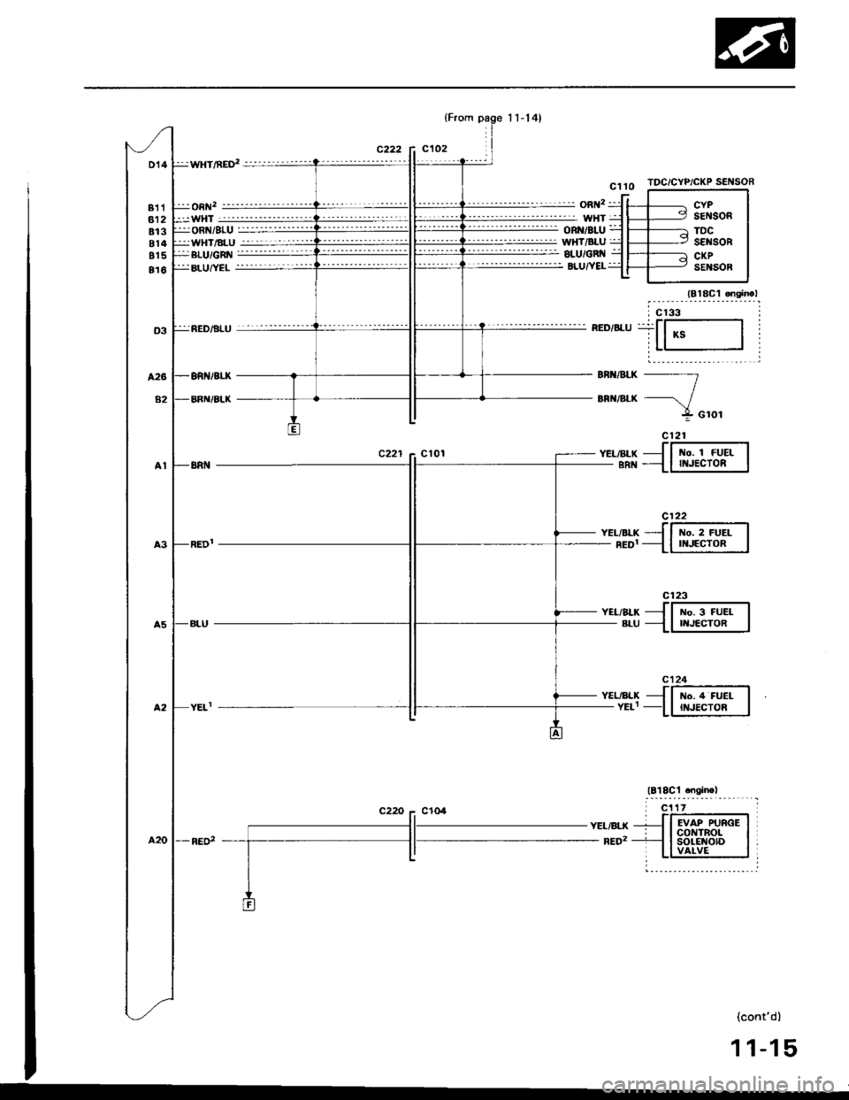
D14
811812813814815
816
:wHT/nED' -'-'--''''-''-'
:j:on 2-"''''-' '- -----
:-WHT--------'-''''-''''
TDC/CYP/CKP SENSOR
c122
t{o. 2 FUELII{JECTOR
c123
No. 3 FUELNJECTOR
c124
t{o. 4 FUELII{JECTOR
:ji oRNi sLU =::::i-:jjjjjjj:ji WHT/ALU jjji-::-:-:::i:jj
YEL/ALXYELI
YEL/BLK- RED2
(cont'd)
11-15
KS
t{o. 1 FUEIII{JECTOR
EVAP PURGEcot{TRoLsoLE {otDVAIVE
Page 232 of 1413
PGM-FI System
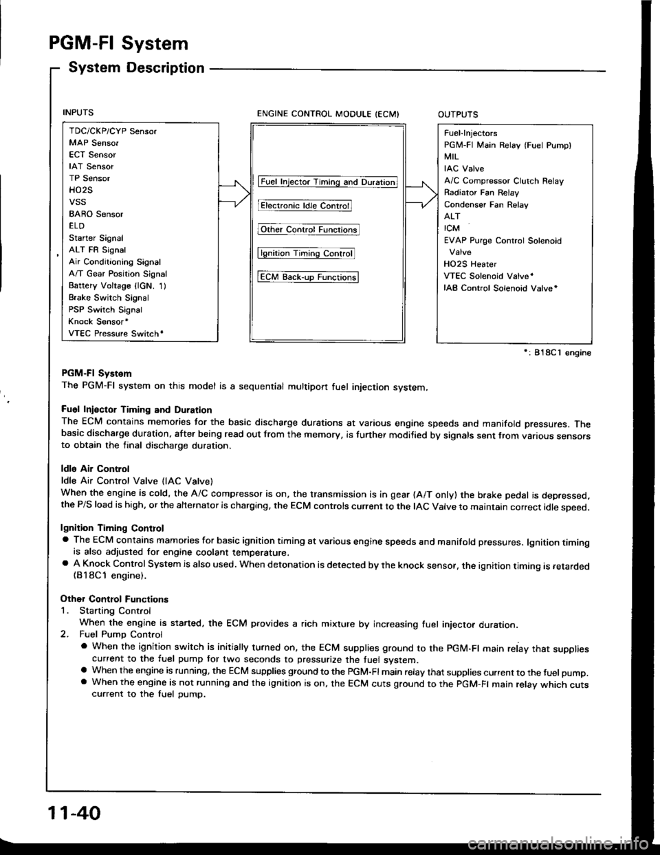
System Description
ENGINE CONTROL MODULE (ECMIOUTPUTS
PGM-Fl System
The PGM-Fl system on this model is a sequential multipon fuel injection system,
Fuol Iniector Timing and Duration
The ECM contains memories tor the basic discharge durations at various engine speeds and manifold pressures. Thebasic discharge duration, after being read out from the memory, is turther modilied by signals sent from vanous sensofsto obtain the final discharge duration.
ldle Air Control
ldle Air Control Valve (lAC Vatve)
When the engine is cold, the A/C compressor is on, the transmission is in gear (A/T only) the brake pedal is depressed,the P/S load is high, or the alternalor is charging, the ECM controls current to the IAC Valve to maintain correct idle soeed.
lgnition Timing Controla The ECM contains mamories for basic ignition timing at various engine speeds and manifold pressures. lgnition timingis also adjusted for engine coolant temperature.a A Knock Control System is also used. when detonation is detected by the knock sensof. the ignition timing is retarded(B18Cl engine).
Other Control Functions
1. Starting Control
When the engine is started. the ECM provides a rich mixture by increasing fuel injector duration.2. Fuel Pump Control
a When the ignition switch is initially turned on, the ECM supplies ground to the PGM-Fl main relay that suppliescurrent to the fuel pump tor two seconds to pressurize the tuel system.a When the engine is running, the ECM supplies gfound to the PGM-Fl main relay that supplies current to the fuel pump.a When the engine is not running and the ignition is on, the ECM cuts ground to the PGM-FI main relav which cutscurrent to the fuel pump.
TDC/CKP/CYP Sensor
MAP Senso.
ECT Sensor
IAT Sensor
TP Sensor
HO2S
vss
BARO Sensor
ELD
Starter Signal
ALT FR Signal
Air Conditioning Signal
A/T Gear Position Signal
Battery Voltage {lcN. 1)
Brake Switch Signal
PSP Switch Signal
Knock Sensor'
VTEC Pressure Switchr
Fuel-lnjectors
PGM-FI Main Relay (Fuel Pump)
MIL
IAC Valve
A/C Compressor Clutch Relay
Radiator Fan Relav
Condenser Fan Relav
ALT
rcM
EVAP Purge Control Solenoid
HO2S Heater
VTEC Solenoid Valve'
IAB Control Solenoid Valve*
lFuet tnjector Timing and Duration]
I Electr..l"ldle Contr;il
Fit'e' contr; Funcrfit
l6tio; Ttntrlg c..trol
tEcM aack-,rp Functiorlsl
': 818C 1 €ngine
11-40
Page 233 of 1413
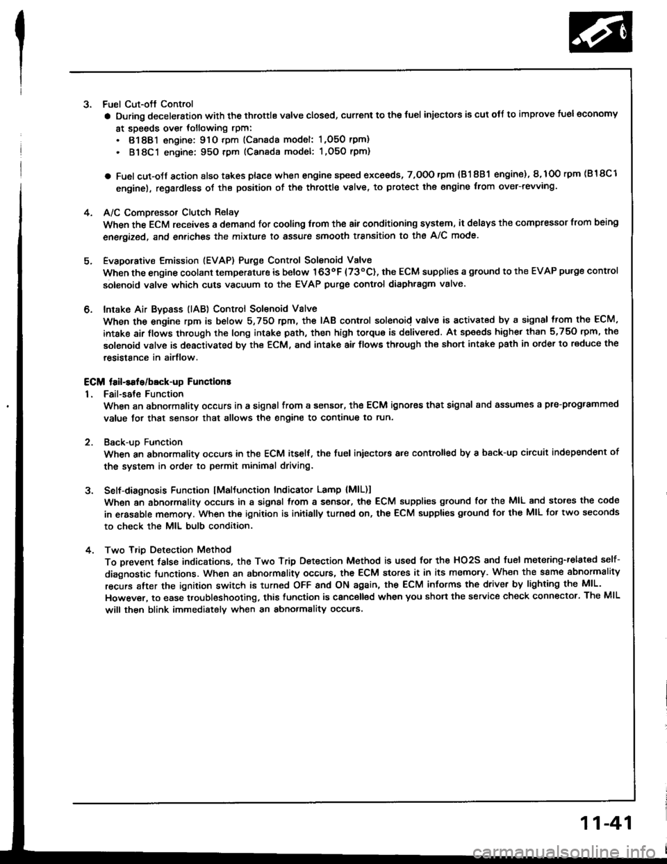
3. Fuel Cut-oft Control
a During deceleration with the throttle valve closed, current to the {uel injectors is cut otJ to improve fuel economy
at speeds over tollowing rpm:
. 8188l engine: 91O tpm (Canada model: 1,O50 rpm)
. 818C1 engine: 95O tpm (Canada model: l,O5O rpm)
a Fuel cut-olf action also takes place when engine speed exceeds, 7,O0O rpm {81 8B1 engine), 8,1O0 rpm (B 18Cl
engine), regardless oI the position of the throttle valve, to protect the engine from ovet-revving.
A/C Compressor Clutch Relay
When the ECM receives a domand for cooling trom the air conditioning system, it del8ys the compressor from being
enetgized, and enriches the mixture to assure smooth transition to the A/C mode.
Evaporative Emission (EVAP) Purge Control Solenoid Valve
When the engine coolant tempersture is below 163oF {73"C), the ECM supplies a ground to the EVAP pu.ge control
solenoid valve which cuts vacuum to the EVAP purge control diaphragm valve.
Intake Air Bypsss (lAB) Control Sol€noid Valve
When the engine rpm is below 5,750 rpm, the IAB control solenoid valve is activated by a signal from the ECM,
intske air flows through the long intake path, then high torque is delivered. At spaeds highe. than 5,750 rpm, the
solenoid valve is deactivated by the ECM, and intake air flows through the short intake path in order to reduce the
resistance in airflow.
ECM fail-safe/bEck-up Functions
1. Fail-sate Function
When an abnormality occurs in a signal from a sensor, the ECM ignores that signal and assumes a pre-progtammed
value tor that sensor that allows the engine to continue to run.
Back-uD Function
When an abnormalitv occurs in the ECM itself, the fuel iniectors are controlled by a back-up citcuit independent of
the system in order to permit minimal driving.
Self-diagnosis Function IMaltunction Indicator Lamp {MlL)1
Wh6n an abnormality occurs in a signal from a sensor, the ECM supplies ground for the MIL and stores the code
in erasable memory. When the ignition is initially turned on, the ECM supplies ground tor the MIL tor two seconds
to check the MIL bulb condition.
Two Trio Detection Method
To prevent tals€ indications, th€ Two Trip Dstection Method is used for the HO2S and fuel metering-related self-
diagnostic tunctions. When an abnormslity occurs, the ECM stores it in its memo.y. Wh€n the ssme sbnormality
recurs alter the ignition switch is turned OFF and ON ag8in, the ECM informs the driver by lighting the MlL.
However, to ease troubleshooting, this function is canc€ll€d when you short the service check connector. The MIL
will then blink immedistelv when an abnormality occurs.
4.
6.
2
4.
11-41