power steering fluid HONDA INTEGRA 1994 4.G Owner's Manual
[x] Cancel search | Manufacturer: HONDA, Model Year: 1994, Model line: INTEGRA, Model: HONDA INTEGRA 1994 4.GPages: 1413, PDF Size: 37.94 MB
Page 662 of 1413
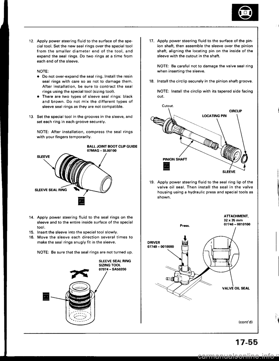
Apply power steering fluid to the surface of the spe-
cial tool. Set the new seal rings over the special tool
from the smaller diameter end of the tool, and
expand the seal rings. Do two rings at a time from
each end of the sleeve,
NOTE:
. Do not over-expand the seal ring. Install the resin
seal rings with care so as not to damage them.
After installation, be sure to contract the seal
rings using the specialtool {sizing tool}.
. There are two types of sleeve seal rings: black
and brown. Do not mix the different types of
sleeve seal rings as they are not compatible.
Set the special tool in the grooves in the sleeve. and
set each ring in each groove securely.
NOTE: After installation, compress the seal rings
with your fingers temporarily.
BALL JOINT BOOT CLIP GUIDEo?MAG - SL001d)
14. Apply power steering fluid to the seal rings on the
sleeve and to the entire inside surface of the special
tool.
15. Insert the sleeve into the specialtool slowly.
16. Move the sl€eve each direction several times to
make the seal rings snugly fit in the sleeve.
NOTE: Be sure that the seal rings are not turned up.
SLEEVE SEAL RINGSIZING TOOL
13.
07974 - 5450200
Cutout,
't7.Apply power steering fluid to the surface ol the pin-
ion shaft, then assemble the sleeve over the pinion
shaft, aligning the locating pin on the inside of the
sleeve with the cutout in the shaft,
NOTE: Be careful not to damage the valve seal ring
when inserting the sleeve.
Install the circlip securely in the pinion shaft groove.
NOTE: Install rh€ circlip with its tapered side facing
OUI.
19. Apply power steering fluid to the seal ring lip of the
valve oil seal. Then install the seal in the valve
housing using a hydraulic press and special tools as
shown.
18.
ATTACHMENT,32x35mm077{6 - 0010100
{cont'd)
VALVE OIL SEAL
17-55
ir
Page 663 of 1413
Steering Gearbox
Reassembly (cont'd)
SI,-EEVE SEAL RINGSBe sure that thesear ings are notturned up, theninstall.
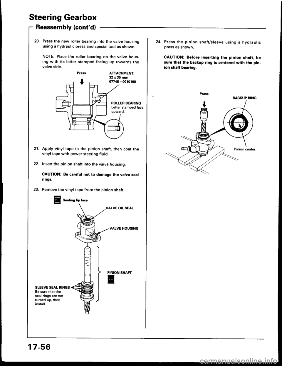
Press the new roller bearing into the valve housing
using a hydraulic press and special tool as shown.
NOTE: Place ths roller bearing on the valve hous-
ing with its letter stamped facing up towards the
valve side.
Pr.33,
I
PINION
E
20.
ATTACHMENT,32x35mm077/aO - (x)1010O
ROLLER BEARINGLetter stamped face
21.Apply vinyl tape to the pinion shaft, then coat thevinyl tape with power steering fluid.
Insert the pinion shaft into the valve housing.
CAUTION: Be carotul not to damage tho valvs soalrings.
23. Remove the vinyltape from the pinion shaft.
Soaling lip frc..
VALVE OIL SEAL
VALVC HOUSING
17-56
24. Press the pinion shaft/sleeve using a hydraulic
Dress as shown.
CAUTION: Before irserting the pinion 3haft, bosuro that the backup ring is csntored with the pin.
ion shaft bearing,
BACKUP BING
Page 664 of 1413
25.
26.
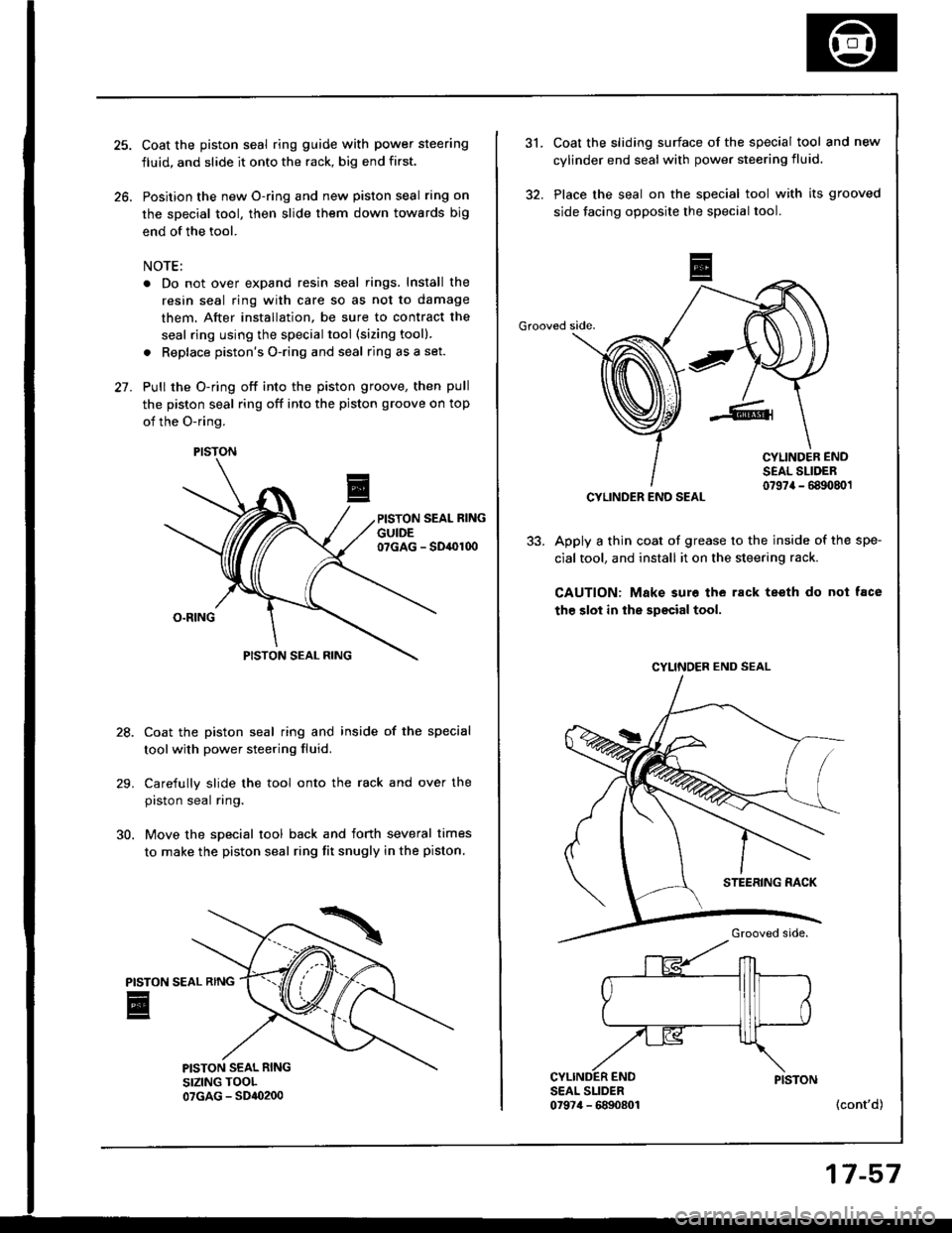
Coat the piston seal ring guide with power steering
fluid, and slide it onto the rack, big end first.
Position the new O-ring and new piston seal ring on
the special tool, then slide them down towards big
end of the tool.
NOTE:
. Do not over expand resin seal rings. Install the
resin seal ring with care so as not to damage
them. After installation, be sure to contract the
seal ring using the special tool (sizing tool).
. Replace piston's O-ring and seal ring as a set.
Pull the O-ring off into the piston groove, then pull
the piston seal ring off into the piston groove on top
of the O-ring.
PISTON SEAL RING
GUIDE07GAG - SD,OI00
28.
30.
O.RING
PISTON SEAL RING
Coat the piston seal ring and inside of the special
toolwith power steering fluid.
Carefully slide the tool onto the rack and over the
piston seal ring.
Move the special tool back and forth several times
to make the piston seal ring fit snugly in the piston.
PISTON
E
PISTON
31.
32.
Coat the sliding surface of the special tool and new
cylinder end seal with power steering fluid.
Place the seal on the special tool with its grooved
side facing opposite the special tool.
Grooved side.
CYLINDER ENDSEAL SLIDER0797a - 6890801
Apply a thin coat of grease to the inside of the spe-
cial tool, and install it on the steering rack.
CAUTION: Make sure the rack teeth do not tace
the slot in the special tool.
SEAL SLIDER0t974 - 6890801(cont'd)
CYLINDER END SEAL
CYLINOER END SEAL
17-57
Page 665 of 1413
Steering Gearbox
Reassembly lcont'dl
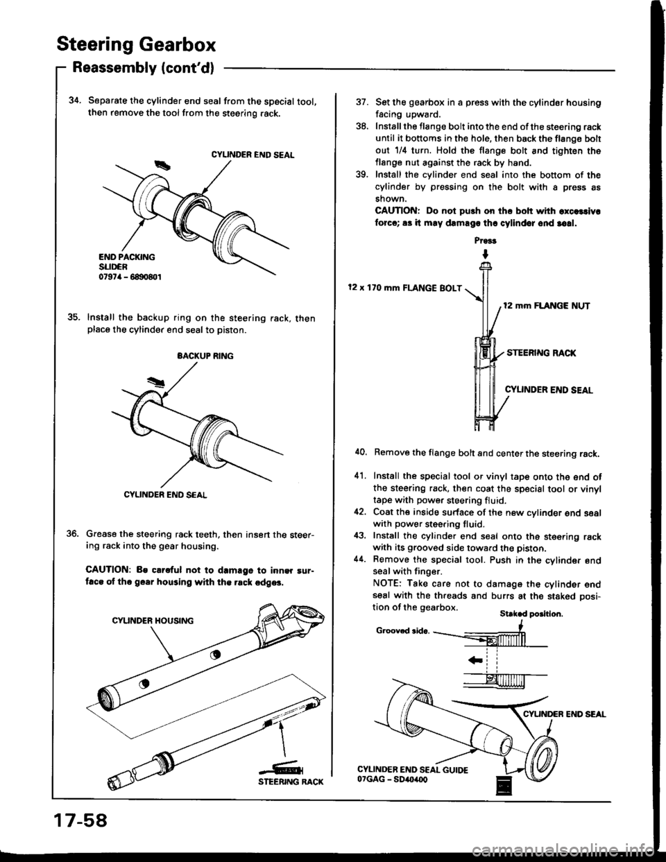
34. Separate the cylinder end seal from the spscial tool,then remove the tool from the steering .ack.
lnstall the backup ring on the steering rack, thenplace the cylinder end seal to piston.
Grease the steering rack teeth, then insert the steer-ing rack into the gear housing.
CAUTION: Be clrs{ul not to d.mage to inn9r !ur-ftca of thc goar housing with th€ rsck cdg6.
CYUNDER END SEAL
BACKUP RING
CYLINDER END SCAL
17-58
CYUNDER END SEAL
37.
'to
Set lhe gearbox in a press with the cylindor housing
facing upward.
Install the flange bolt into the end of the steering rack
until it bottoms in the hole, then back the flang€ bolt
out 1/il turn. Hold the flange bolt and tighten the
flange nut against the rack by hand.
Install the cylinder end seal into the bottom of the
cylinder by pressing on the bolt with a press as
shown.
CAUTION: Do not push on ihc bolt with excelcivr
forcc; 83 it may dEmago thr cylindor ond 3o!1.
Pr9!t
I
12 x 170 mm FLANGE BOLT
12 mm FLANGE NUT
STEERING RACK
CYUNDER END SEAL
41.
Remove the flange bolt and center the steering rack.
Install the special tool or vinyl tape onto the end ofthe steering rack, then coat the special tool or vinyltape with power steering fluid.
Coat the inside surface of the new cylinder end sealwith power steering fluid.
Install the cylinder end seal onto the ste€ring rackwith its grooved side toward the piston.
Remove the special tool. Push in the cylinder endseal with finger.
NOTE: Take care not to damage the cylinder endseal with the threads and burrs at the stakod oosi-tion of the gearbox.St k d po3ition.
c.oov.d3id...--#
IL ll
Page 1126 of 1413
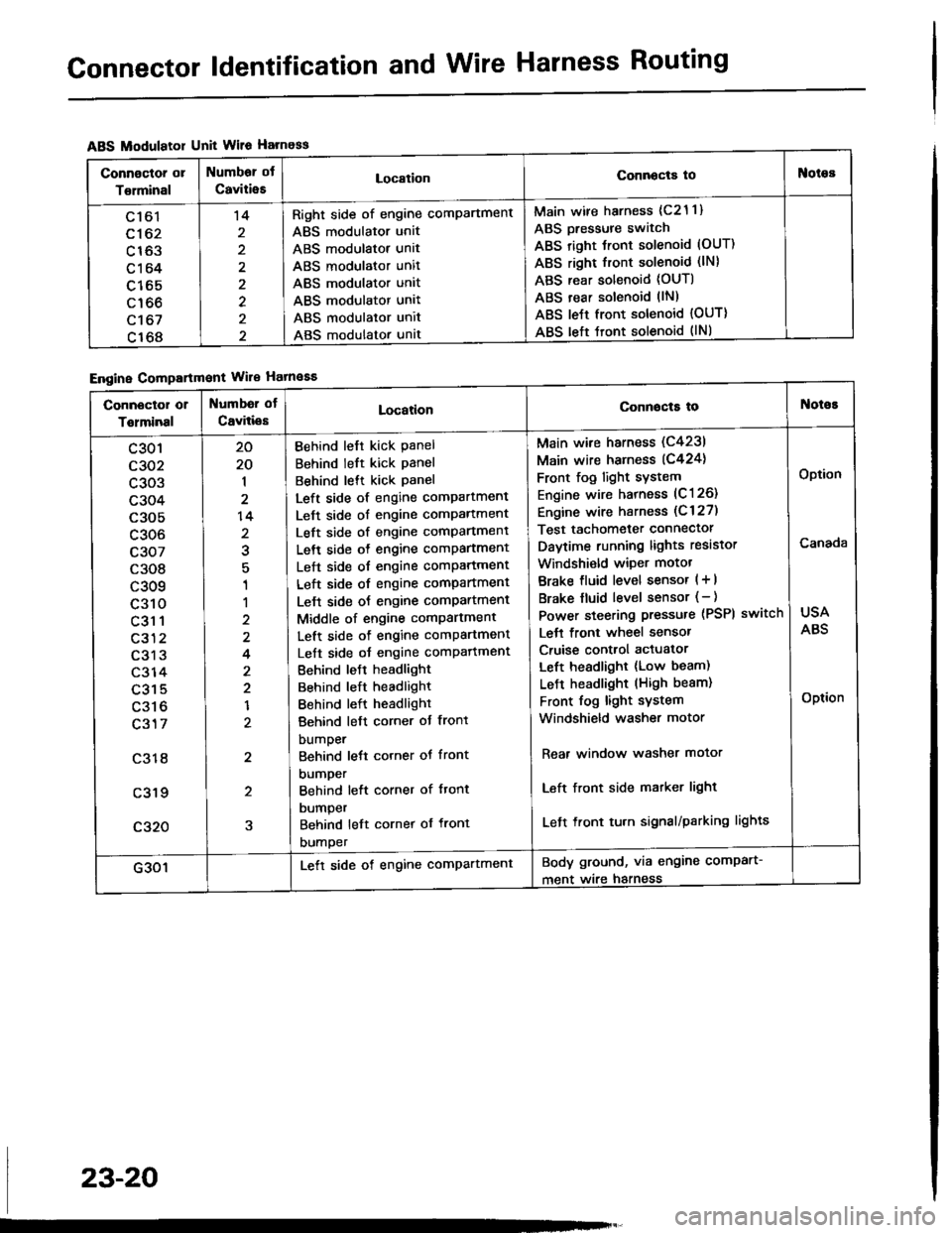
Connector ldentification and Wire Harness Routing
ABS Modulatol Unit Wile Harness
Engine Compartmont Wile Hatnaaa
Connoctor or
Torminal
Numbor ot
CaviiieELocationConnocta tooies
Ltol
c162
c163
c164
c165
c166
c't 67
c168
't4
2
2
Right side of engine comPartment
ABS modulator unit
ABS modulator unit
ABS modulator unit
ABS modulator unit
ABS modulator unit
ABS modulator unit
ABS modulator unat
Main wire harness (c21 1)
ABS Dressure switch
ABS right Jront solenoid (OUT)
ABS right front solenoid (lN)
ABS rear solenoid (OUT)
ABS rear solenoid llN)
ABS le{t front solenoid {OUT)
ABS left tront solenoid (lNl
Connector or
Tolminal
Numbd of
CaviliesLocationConnocta tot{oioE
c301
c302
c303
c304
c305
c306
c307
c308
c309
c310
c31 1
c312
c313
c314
c315
c316
c317
c318
c319
c320
20
20
1
2
14
2
1
1
2
4
2
2
1
2
2
5
Behind left kick Panel
Behind left kick panel
Behind lett kick Panel
Left side of engine compartment
Left side of engine comPartment
Left side of engine comPartment
Left side o{ engine comPartment
Left side of engine comPartment
Left side of engine compartment
Lelt side oJ engine comPartment
Middle of engine comPartment
Left side of engine comPartment
Left side oJ engine comPafiment
Behind leJt headlight
Behind left headlight
Behind left headlight
Behind left corner ot front
bumper
Behind lett corner ot front
DUmper
Behind left corner of ftont
DUmper
Behind left cornet of front
DUmper
Main wire harness (C4231
Main wire harness (C424)
Front fog light sYstem
Engine wire harness (C126)
Engine wire harness (C 127)
Test tachometer connector
Daytime running lights resistor
Windshi€ld wiper motot
Brake fluid level sensor ( + |
Brake fluid level sensor (- )
Power steering pressure (PSPI
Lett front wheel sensor
Cruise control actuator
Left headlight (Low beam)
LeJ-t headlight (High beam)
Front fog light system
Windshield washer motor
switch
Rear window washer motor
Left front side matker light
Left front tu.n signal/parking lights
USA
ABS
Option
Canada
Option
G301Lett side of engine comPartmentBody ground, via engine comPart-
ment wire harness
23-20