ECU HONDA INTEGRA 1994 4.G Workshop Manual
[x] Cancel search | Manufacturer: HONDA, Model Year: 1994, Model line: INTEGRA, Model: HONDA INTEGRA 1994 4.GPages: 1413, PDF Size: 37.94 MB
Page 93 of 1413
14.
16.
Installthe timing belt {see page 6-12).
Adjust the valve clea.ance (see page 6-31.
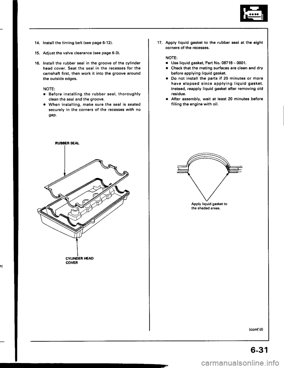
Install the rubber seal in the groove of the cylinder
head cover. Seat the seal in the recesses for thg
camshaft first, th€n work it into the groove around
the outside edges,
NOTE:
. Before installing the rubber seal, thoroughly
clean the seal and the groove.
. When installing, make sure the seal is seated
securely in the corners of the recass€s with no
gap.
CYUNDER HEADCOVER
RUBAER SEAL
17.Apply liquid gask€t to the rubber seal at the eight
corners of the recesses.
NOTE:
. Use liquid gaskst, Part No. 08718 - 0001.
. Check that the mating surfaces are cl€an and dry
before applying liquid gasket.
. Do not install the parts if 20 minutes or mor6
havs elapsod sinco applying liquid gasket.
Instead, reapply liquid gasket after removing old
reaidue.
. After assembly, wait at lsast 20 minutes before
filling the engine with oil.
Apply liquid g.sket tothe shaded areas.
(cont'd)
6-31
Page 139 of 1413
11.
12.
13.
Cylinder Head
Installation lcont'd)
lnstallthe timing belt lsee page 6-51).
Adjust the valve clearance (see page 6-44).
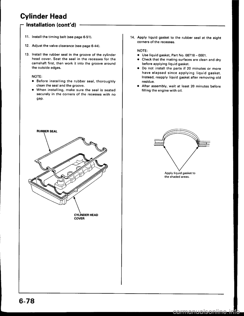
Install the rubber seal in the groove of the cylinder
head cover. Seat the seal in the recesses for the
camshaft first, then work it into the groove around
the outside edges.
NOTE:
. Before installing the rubber seal. thoroughly
clean the seal and the groove.
. When installing, make sure the seal is seatedsecurely in the corners of the recesses with nogap.
COVER
6-78
14. Apply liquid gasket to the rubbe. seal at the eightcorne.s of the recesses.
NOTE:
. Use liquid gasket, Part No. 08718 - 0001.. Check that the mating surfaces are clean and dry
before applying liquid gasket.
a Do not install the parts if 20 minutes or more
have elapsed since applying liquid gasket.
Instead,.eapply liquid gasket after removing oldresidue.
r After assembly, wait at least 20 minutes beforefilling the engine with oil.
Apply liquid gasket tothe shaded areas.
Page 156 of 1413
Piston
lnstallation
'1.
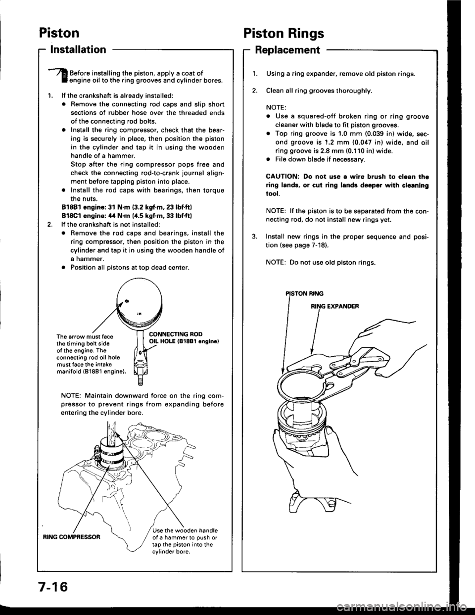
Before installing the piston, apply a coat ofengine oil to the ring grooves and cylinder bores.
lf the crankshaft is already installed:
. Remove the connecting rod caps and slip short
sections of rubber hose ove. the threaded ends
of the connecting rod bolts.
a Install the ring compressor, check that the bear'
ing is securely in place, then position the piston
in the cylinder and tap it in using the wooden
handle of a hammer.
Stop after the ring compressor pops free and
check the connecting rod-to-crank journal align-
ment before tapping piston into place.
. Install the rod caps with bearings, then torque
the nuts,
81881 ongino: 31 N.m {3.2 kgf.m, 23 lbf.ftl
818C1 cngino: 44 N'm 1,t.5 kgf.m, 33 lbf.ftl
lf the crankshaft is not installed:
o Remove the rod caps and bearings. install the
ring compressor, then position the piston in the
cylinder and tap it in using the wooden handle of
a nammer.
. Position all Distons at toD dead center.
CONNECTING RODOIL HOI-E (Br8Bl onginelThe arrow must facethe timing belt sideof the engine. Theconnecting rod oil holemust lace the intak€manifold {81881 €ngine).
NOTE: Maintain downward force on the ring com-
pressor to prevent rings from expanding before
entering the cylinder bore,
BING COMPRESSORUse the wooden handleof a hammer to push ortap the piston into thecylinder bore.
Piston Rings
Replacement
1.Using a ring expander, remove old piston rings.
Clean all ring g.ooves thoroughly.
NOTE:
. Use a squared-oJf broken ring or ring groove
cleaner with blade to fit piston grooves.
. Top ring groove is 1.0 mm (0.039 in) wide, sec-
ond groove is 1.2 mm (0.047 in) wide. and oil
ring groove is 2.8 mm (0.110 in) wide.. File down blade if necessary.
CAUTION: Do not use a wire brush to cloan thr
ring lands, or cut ring lands dsopo. with cl€aning
tool.
NOTE: lf the piston is to be separated from the con-
necting rod, do not install new rings yet.
Install new rings in the prope. sequence and posi-
tion (see page 7-18).
NOTE: Do not use old piston rings.
Page 188 of 1413
Radiator
Replacement
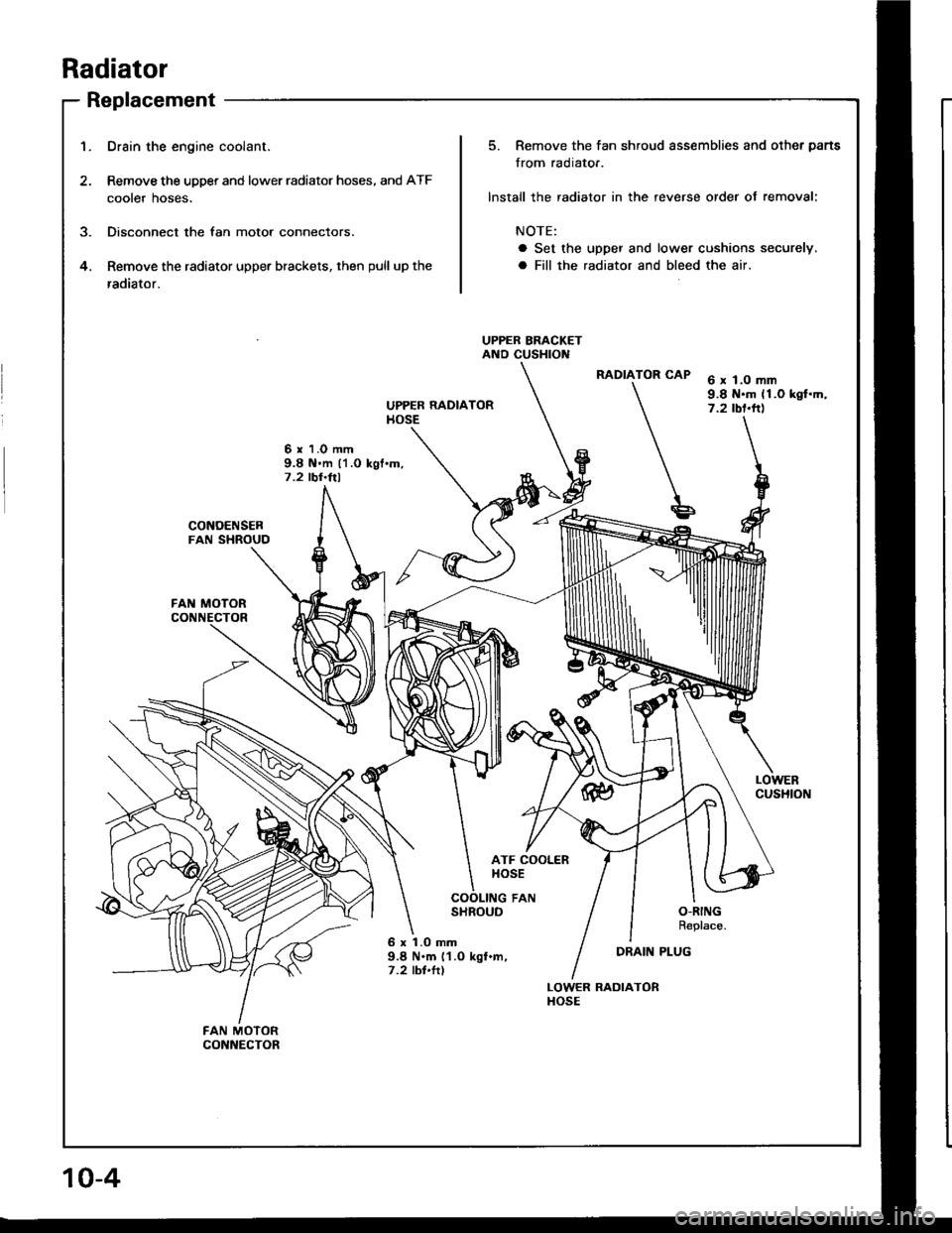
1.Drain the engine coolant.
Remove the upper and lower radiator hoses, and ATF
cooter noses.
Disconnect the fan motor connectors.
Remove the radiator upper brackets, then pull up the
radiator.
5. Remove the fan shroud assemblies and other parts
from radiato..
lnstall the radiator in the reverse order of removal:
NOTE:
a Set the upper and lower cushions securely.
a Fill the radiator and bleed the air.4.
UPPER BRACKETAND CUSHTOl{
RADIATOR CAP
t
e
6 x l.O mm9.8 N.m (1.O kgt.m,7.2 rbf.ft)
6 x 1.0 mm9.8 il.m 11.O kgt'm,7.2 lbr.ftl
FAN MOTOR
CUSHION
SHROUDO-RINGReplace.
6 x 1.0 mm9.8 N.m ('l.O kgl.m,7.2 tbl.ttl
DRAIN PLUG
LOWER RADIATORHOSE
Page 189 of 1413
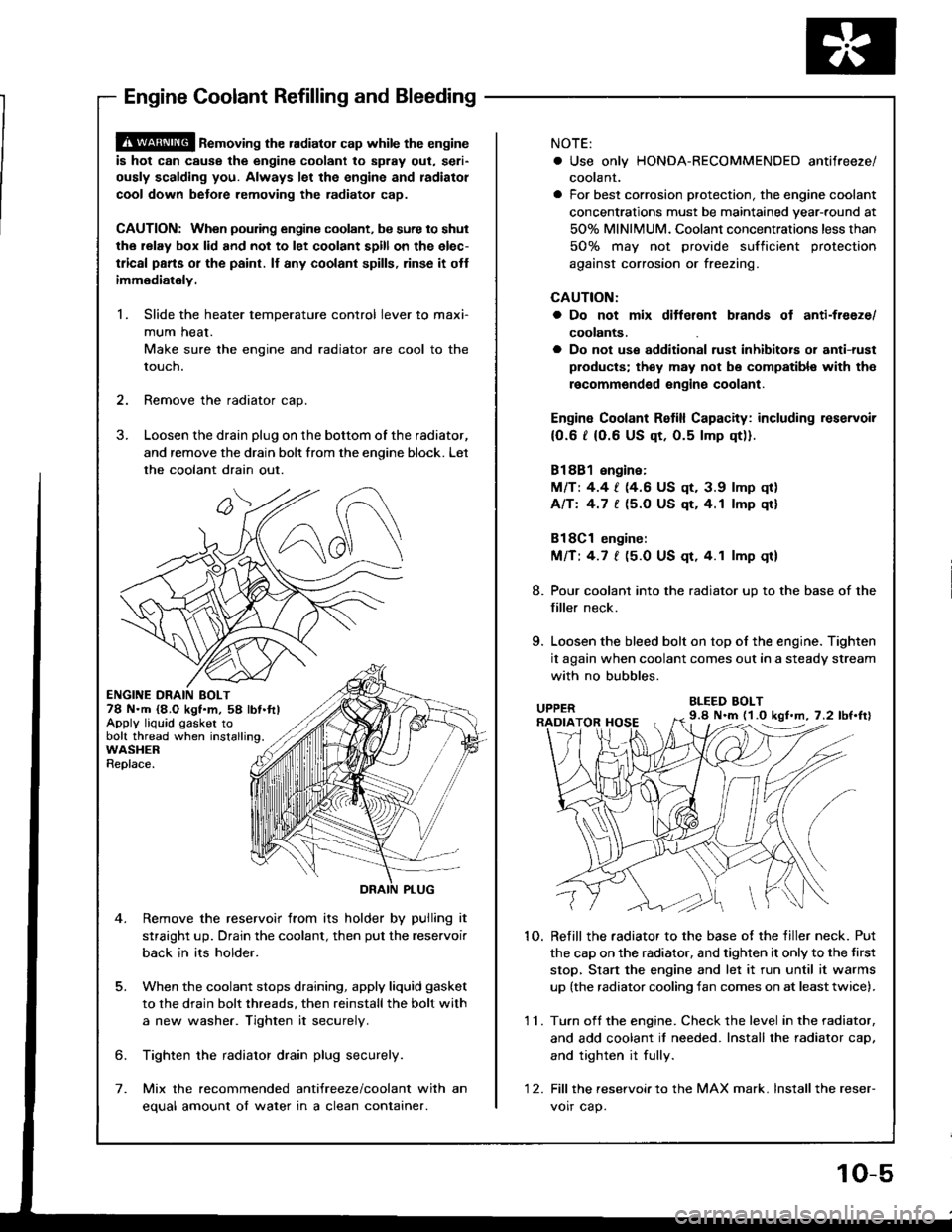
@ ne-oving the radiator cap while the engine
is hot can cause the engine coolant to splay out, seri-
ously scalding you. Always let the engine and radiatol
cool down betore removing the radiator cap.
CAUTION: When poudng engine coolant, be sure to shut
the relay box lid and not to let coolant spill on the elec-
tlical pans or the paint. ll any coolant spills, rinse it otf
immediately.
1. Slide the heater temperature control lever to maxi-
mum heat.
Make sure the engine and radiator are cool to the
touch.
2. Remove the radiator cao.
3. Loosen the drain plug on the bottom of the radiator,
and remove the drain bolt from the enoine block. Let
the coolant drain out.
ENGINE DRAIN BOLT78 N.m {8,O kgt.m, 58 lbt.ftlApply liquid gasker tobolt thread when installing.WASHERReplace.
5.
Remove the reservoir from its holder by pulling it
straight up. Drain the coolant, then put the reservoir
back in its holder.
When the coolant stops draining, apply liquid gasket
to the drain bolt threads, then reinstallthe bolt with
a new washer. Tighten it securely
6. Tighten the radiator drain plug securely.
7. Mix the recommended antifreeze/coolant with an
equal amount of water in a clean container.
NOTE:
. Use only HONDA-RECOMMENOED antifreeze/
coolant.
a For best corrosion protection, the engine coolant
concentrations must be maintained year-round at
50% MINIMUM. Coolant concentrations less than
50% may not provide sufficient protection
against corrosion or freezing.
CAUTION:
a Do not mix ditterent blands ot anti-freeze/
coolants.
a Do not use additional rust inhibitois or anti-rust
products; they may not bs compatibl€ with the
recommgndsd engins coolant.
Engin€ Coolant Retill Capacity: including reservoir
{0.6 t (0.6 US qt, 0.5 lmp qt)).
81881 engine:
MlTt 4.4 | (4.6 US qt, 3.9 lmp qr)
Afft 4.7 [ (5.O US qt,4.1 lmp qt]
Bl8Cl engine:
Mnt 4.7 | (5.0 US qt.4.1 lmp qt)
8. Pour coolant into the radiator up to the base of the
filler neck.
9. Loosen the bleed bolt on top of the engine. Tighten
it again when coolant comes out in a steady stream
with no bubbles.
BLEED BOLT
1O. Refill the radiator to the base of the tiller neck. Put
the cap on the radiator. and tighten it only to the tirst
stop, Stan the engine and let it run until it warms
up (the radiator cooling fan comes on at leasttwice).
11. Turn oft the engine. Check the level in the radiator,
and add coolant it needed. Install the radiator caD,
and tighten it fully.
'1 2. Fill thereservoirto the MAX mark. lnstallthe reser-
voir cap.
9.8 N.m (1.O kgl.m, 7.2 lbf.ftl
Engine Coolant Refilling and Bleeding
10-5
Page 204 of 1413
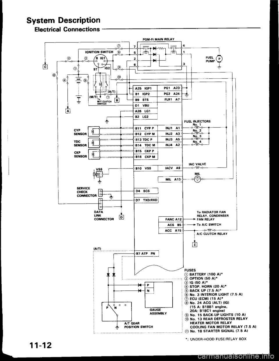
System Description
Electrical Connections
PGM.FI MAII{ RELAY
- rc2l L
IllLii |
ril.i--r {a/Tl
To BAOIATOR FAt!RETAY, CONDENSERFAI{ RELAY
To A/C SWITCH
FUEL INJ€CTORS
@
DATALIIIKco t{EcToR
fUELPUMP
A/C CLUTCH RELAY
FUSES
O BATTERY I1OO AI*
@ oPTroN t50 alr
o rG {50 A).
@ sroP. HoBN {2O Al*
@ BACK UP (7.5 Al*
@ No. 3 INTERIOR LIGHT {7.5 A)
O Ecu (EcMt (1s A)'
@) No. 24 ACG (ALTI 0Gl{15 A: 81881 sngin6,2OA:818C1 6n9ine)
@ No. 15 BAcK-uP LlcHTs llo Al
@ No. 13 REAR DEFROSTER RELAYHEATER MOTOR RELAYCOOLING FAN MOTOR RELAY I7.5 A}
O No. l8 STARTER SIGNAL 17.5 A)
*: UNDER-HOOD FUSE/RELAY BOX
11-12
A/T GEAR
Page 233 of 1413
3. Fuel Cut-oft Control
a During deceleration with the throttle valve closed, current to the {uel injectors is cut otJ to improve fuel economy
at speeds over tollowing rpm:
. 8188l engine: 91O tpm (Canada model: 1,O50 rpm)
. 818C1 engine: 95O tpm (Canada model: l,O5O rpm)
a Fuel cut-olf action also takes place when engine speed exceeds, 7,O0O rpm {81 8B1 engine), 8,1O0 rpm (B 18Cl
engine), regardless oI the position of the throttle valve, to protect the engine from ovet-revving.
A/C Compressor Clutch Relay
When the ECM receives a domand for cooling trom the air conditioning system, it del8ys the compressor from being
enetgized, and enriches the mixture to assure smooth transition to the A/C mode.
Evaporative Emission (EVAP) Purge Control Solenoid Valve
When the engine coolant tempersture is below 163oF {73"C), the ECM supplies a ground to the EVAP pu.ge control
solenoid valve which cuts vacuum to the EVAP purge control diaphragm valve.
Intake Air Bypsss (lAB) Control Sol€noid Valve
When the engine rpm is below 5,750 rpm, the IAB control solenoid valve is activated by a signal from the ECM,
intske air flows through the long intake path, then high torque is delivered. At spaeds highe. than 5,750 rpm, the
solenoid valve is deactivated by the ECM, and intake air flows through the short intake path in order to reduce the
resistance in airflow.
ECM fail-safe/bEck-up Functions
1. Fail-sate Function
When an abnormality occurs in a signal from a sensor, the ECM ignores that signal and assumes a pre-progtammed
value tor that sensor that allows the engine to continue to run.
Back-uD Function
When an abnormalitv occurs in the ECM itself, the fuel iniectors are controlled by a back-up citcuit independent of
the system in order to permit minimal driving.
Self-diagnosis Function IMaltunction Indicator Lamp {MlL)1
Wh6n an abnormality occurs in a signal from a sensor, the ECM supplies ground for the MIL and stores the code
in erasable memory. When the ignition is initially turned on, the ECM supplies ground tor the MIL tor two seconds
to check the MIL bulb condition.
Two Trio Detection Method
To prevent tals€ indications, th€ Two Trip Dstection Method is used for the HO2S and fuel metering-related self-
diagnostic tunctions. When an abnormslity occurs, the ECM stores it in its memo.y. Wh€n the ssme sbnormality
recurs alter the ignition switch is turned OFF and ON ag8in, the ECM informs the driver by lighting the MlL.
However, to ease troubleshooting, this function is canc€ll€d when you short the service check connector. The MIL
will then blink immedistelv when an abnormality occurs.
4.
6.
2
4.
11-41
Page 235 of 1413
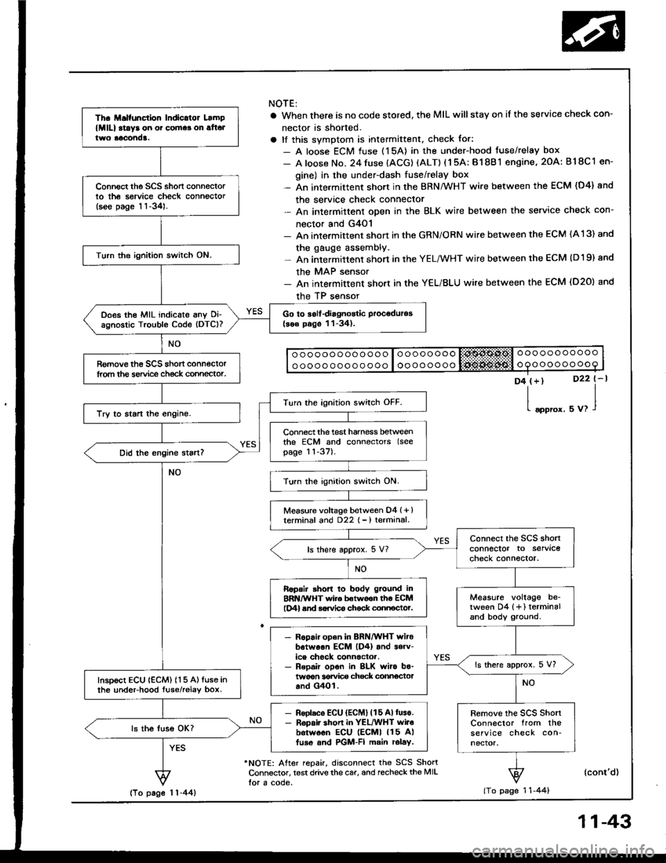
Th. ll.lfunction Indicltor Lamp
lMlll at!y3 on o. cornaa on alt6ltwo aacond!.
Connect the SCS short connectorto th6 sorvice check connector(see page 11-34).
Turn the ignition switch ON.
Go to iolfdiagnostic Proceduros(se€ pago 11-34).Does the MIL indicate anv Oi-agnostic Trouble Code (DTC)?
Romove th€ SCS shon connectorlrom the service ch€ck connector.
Turn the ignition switch OFF.
Try to start the engine.
Connect the test harness betweenthe ECM and connectors (see
page 11-37).
Turn the ignition switch ON.
Measure voltage botween D4 (+ )terminal and D22 { - ) terminal.
connect the SCS shonconnector to servlcecheck connector.ls there approx. 5 V?
Ropair shon to body g.ound inBRN/WHT wire betwoon th6 ECMlD4) end sorvlco chock connocto?.Measure voltage be_tween D4 {+} terminaland body ground.
- R6pair open in BRN/WHT witobotwoon EcM lD4) and s6rv-ice chock connactor.- Repoir opon in BLK wiro bo-twoon 36rvi@ chock connectoaand G4Ol.
ls there approx. 5 V?
InsDoct ECU {ECM) 115 A) tuse inth6 undeFhood luse/relav box.
- Rsolaco ECU {ECM} (15 Allus€.- R6pair shon in YEL/WHT wilobotw6on ECU lEcMl 115 A)fuso and PGM-FI main rolay.
Remove the scs shortConnector from theservice check con-nector.
ls the luss OK?
NOTE:
a When there is no code stored, the MIL willstay on if the service check con-
nector is shorted.
a tf this svmotom is intermittent, check for:
- A loose ECM fuse (15A) in the under-hood tuse/relay box
- A loose No. 24 fuse (ACG) (ALT) ( 1 5A: B1 8B 1 engine, 2OA: B18C 1 en-
gine) in the under-dash fuse/relay box- An intermittent short in the BRN/WHT wire between the ECM (D4) and
the service check connector- An intermittent oDen in the BLK wire between the service check con-
nector and G4O1- An intermittent shon in the GRN/ORN wire between the ECM (A 13) and
the gauge assembly.- An intermittent short in the YELMHT wire between the ECM (D19) and
the MAP sensor- An intermittent short in the YEL/BLU wire between the ECM (D20) and
the TP sensor
o ooooo ooo ooo o loooooooo liii:$A$.Ps,l o oo ooo ooooo
o oooo ooo o o ooo I oooooooooooooooooo
D4 (+)
l"oo,o'.
D22 t-l
uu,l
'NOTE: After repair, disconnect the SCS ShortConnsctor, test drive the car, and recheckthe MIL
lor a code.
(cont'd)
(To page 1 'l -44)lTo page 1 1-44)
11-43
Page 301 of 1413
![HONDA INTEGRA 1994 4.G Workshop Manual Fuel Supply System
PGM-Fl Main Relay (contdl
BLU
BLU/wHt
Bt-xNOTE:. M/T: Clutch pedal mustbe depressed.. A/T: Transmission in
N or E] position.
BLK/ YEL/YEL BLK
Tloubloshooting
{To page 11 113}
- Eng HONDA INTEGRA 1994 4.G Workshop Manual Fuel Supply System
PGM-Fl Main Relay (contdl
BLU
BLU/wHt
Bt-xNOTE:. M/T: Clutch pedal mustbe depressed.. A/T: Transmission in
N or E] position.
BLK/ YEL/YEL BLK
Tloubloshooting
{To page 11 113}
- Eng](/img/13/6067/w960_6067-300.png)
Fuel Supply System
PGM-Fl Main Relay (cont'dl
BLU
BLU/wHt
Bt-xNOTE:. M/T: Clutch pedal mustbe depressed.. A/T: Transmission in
N or E] position.
BLK/ YEL/YEL BLK
Tloubloshooting
{To page 11 113}
- Engino will not sran.- Inspection oI PGM-FI main re-lay and rolay ha.n6!a.
Check lor continuitv between BLKterminal @ and body ground.
Rapair open in BLK wire botwoonPGM-FI main.el6y and GIO'l llo-catod at thormostot housingl.
Measure the voltage betweenYELMHT terminal @ and bodyground.- Roplaco th. ECU IECMI(15 Allus6 in tho under-hood fu!o/r6-lay box.- Ropair opan or short in theYEL/WHT wil6 botwosn thePGM-FI main rolay and the ECU
{EcMl 115 A} luso.
ls there battery voltage?
Turn the ignition switch ON.
Measure the voltage betweenBLK/YEL terminal @ and bodyground.- Reolac. ths No. 24 ACG {ALT}{lcl {15 A:81881 6ngino, 20A: Bl8Cl engin6) tuse in thoundor-dash fuso/rolaY box.- Ropaii op6n or rhon in thoBLK/YEL wiro botwoen thoPGM-FI main ielay and th€ No.24 ACG {ALT) flG} {'�15 A:818Bi ongine, 20 A: 818Cionginol fuso.Turn the ignition switch to theSTART position.
Measure the voltage betweenBLUMHT terminsl @ and bodyground.
- Replaco the l\lo. 18 STARTERSIGNAL {7.5 A} fuso in thoundor-dash fuaa/rolay box.- R6pai. open or short in thoBLU/WHT wire botweon thsPGM-FI main relay and tho No.1A STARTER SIGNAL I7.5 AIluse.
11-112
Page 372 of 1413

Countershaft Assembly
Disassembly
13-30
't.Securely clamp the countershaft assembly in a
bench vise with wood blocks.
Raise the locknut tab from the groove in the coun-
tershaft, then remove the locknut and the spring
washer.
4,Remove the bearing outer .ace, then remove the
needle bearing using a bearing puller as shown.
2.
BEARING PULLER
BEARING
Remove the ball bearing using a bearing puller as
shown.
CAUTION: Romove the gclrs using a pross and tho
steol blocks rs shown. U3a of a l.w.typo pullor can
cau36 damagg to tho gsar iocth.
Support 4th gear on steel blocks. and press the
countershaft out of sth and 4th gears, as shown.
PULlTR
\-Y