transmission HONDA INTEGRA 1994 4.G Owner's Manual
[x] Cancel search | Manufacturer: HONDA, Model Year: 1994, Model line: INTEGRA, Model: HONDA INTEGRA 1994 4.GPages: 1413, PDF Size: 37.94 MB
Page 147 of 1413
Flywheel and Drive Plate
Replacement
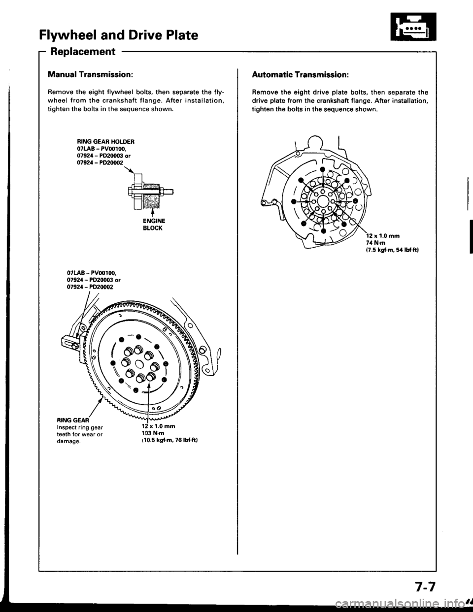
Manual Transmission:
Remove the eight flywheel bolts, then separate the lly-
wheel from the crankshaft flange. After installation,
tighten the bolts in the sequence shown.
r10.5 kgi.m,76lbt.ftl
RING GEAR HOLOERo?LAB - PV00100,07924 - PO2IX)03 or07924 - PD20/m�2
\
n.t=?4
fut!!-+-rt=tz-21I lvaz'Z-+
ENGINEBLOCK
o -o.r \
/ oo^t,
\..?bi
/ AK{:{AAo
rs#*ffi_9
Automatic Transmission:
Remove th€ eight drive plate bolts, then separate the
drive plate from the crankshaft flange, After installation,
tighten the bolts in the sequence shown.
r t.0 mmt,l N.m(7.5 kg{.m, 54 lbf.ft}
7-7
Page 232 of 1413
PGM-FI System
System Description
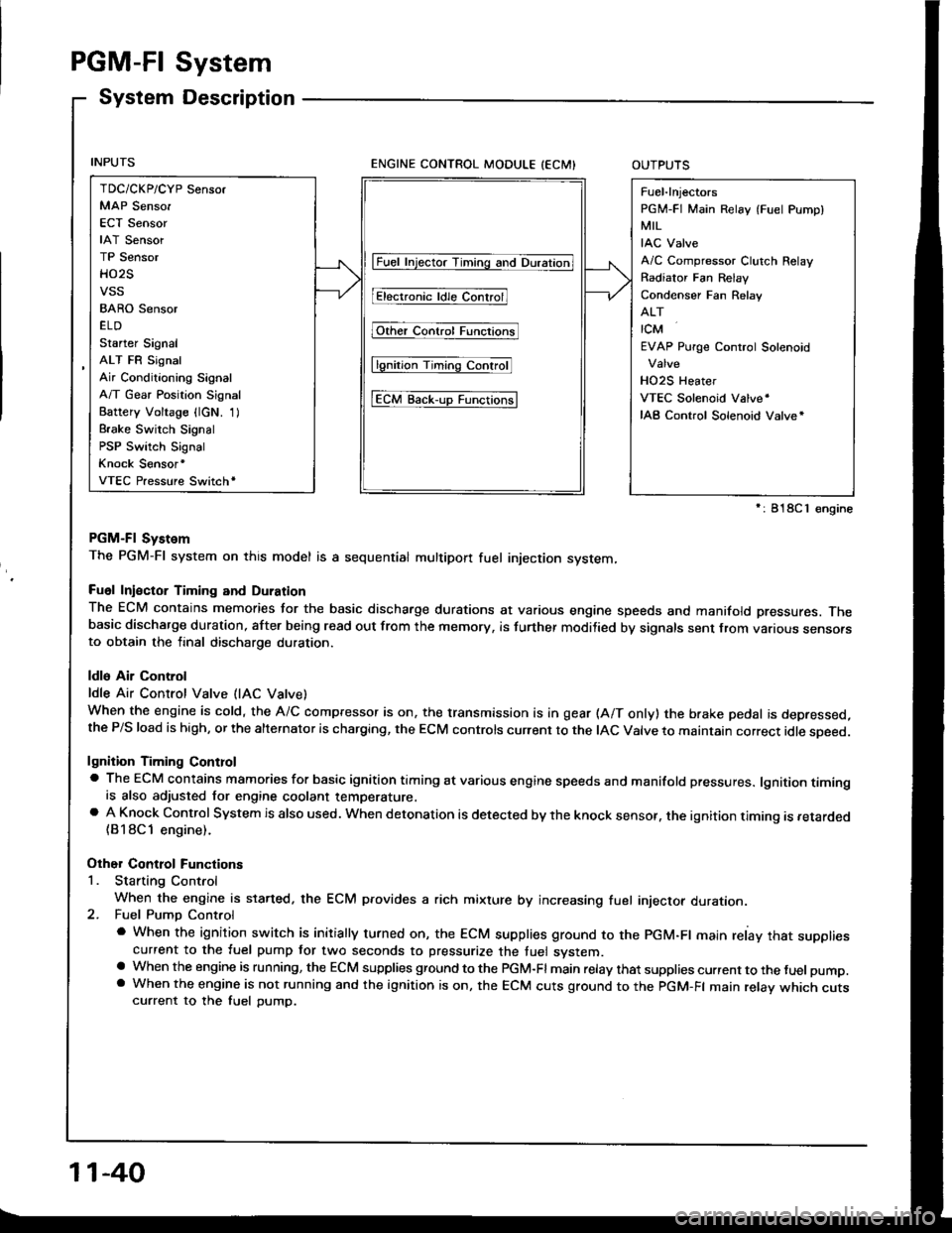
ENGINE CONTROL MODULE (ECMIOUTPUTS
PGM-Fl System
The PGM-Fl system on this model is a sequential multipon fuel injection system,
Fuol Iniector Timing and Duration
The ECM contains memories tor the basic discharge durations at various engine speeds and manifold pressures. Thebasic discharge duration, after being read out from the memory, is turther modilied by signals sent from vanous sensofsto obtain the final discharge duration.
ldle Air Control
ldle Air Control Valve (lAC Vatve)
When the engine is cold, the A/C compressor is on, the transmission is in gear (A/T only) the brake pedal is depressed,the P/S load is high, or the alternalor is charging, the ECM controls current to the IAC Valve to maintain correct idle soeed.
lgnition Timing Controla The ECM contains mamories for basic ignition timing at various engine speeds and manifold pressures. lgnition timingis also adjusted for engine coolant temperature.a A Knock Control System is also used. when detonation is detected by the knock sensof. the ignition timing is retarded(B18Cl engine).
Other Control Functions
1. Starting Control
When the engine is started. the ECM provides a rich mixture by increasing fuel injector duration.2. Fuel Pump Control
a When the ignition switch is initially turned on, the ECM supplies ground to the PGM-Fl main relay that suppliescurrent to the fuel pump tor two seconds to pressurize the tuel system.a When the engine is running, the ECM supplies gfound to the PGM-Fl main relay that supplies current to the fuel pump.a When the engine is not running and the ignition is on, the ECM cuts ground to the PGM-FI main relav which cutscurrent to the fuel pump.
TDC/CKP/CYP Sensor
MAP Senso.
ECT Sensor
IAT Sensor
TP Sensor
HO2S
vss
BARO Sensor
ELD
Starter Signal
ALT FR Signal
Air Conditioning Signal
A/T Gear Position Signal
Battery Voltage {lcN. 1)
Brake Switch Signal
PSP Switch Signal
Knock Sensor'
VTEC Pressure Switchr
Fuel-lnjectors
PGM-FI Main Relay (Fuel Pump)
MIL
IAC Valve
A/C Compressor Clutch Relay
Radiator Fan Relav
Condenser Fan Relav
ALT
rcM
EVAP Purge Control Solenoid
HO2S Heater
VTEC Solenoid Valve'
IAB Control Solenoid Valve*
lFuet tnjector Timing and Duration]
I Electr..l"ldle Contr;il
Fit'e' contr; Funcrfit
l6tio; Ttntrlg c..trol
tEcM aack-,rp Functiorlsl
': 818C 1 €ngine
11-40
Page 238 of 1413
PGM-FI System
Heated Oxygen Sensor lHO2Sl
ztRcot{lAELEiIE'{T
HEATER
- --.'!- - -__-
lrPl _l !l-
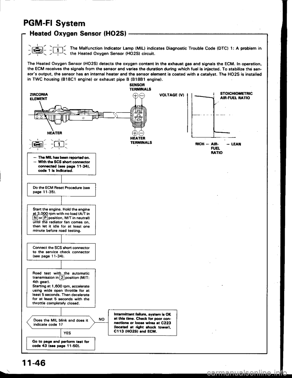
-fi-l: The Malfunction Indicator Lamp (MlL) indicates Diagnostic Troubls Code (DTC) 1: A problsm in
/? the Heated Oxygen Sonsor (HO2S| circuit.
The Heated Oxygen Sensor IHO2S) det€cts th6 oxygon contont in th6 exhaust gas and signals th6 ECM. In operation,
the ECM receiv€s th6 signals trom the sensor and vari€s the duration during which tu6l is iniocted. To stabilize thd sen-aor's output, tho sensor has 8n intarnal heater and the sensor olemant is coatod with a catslyst. The HO2S is installod
in TWC housing (B18Cl engine) or exhaust pipe B (Bl8Bl €ngine).
sEl{SORTERMII{ALS
:tz-t6l-/ --.- \
VOLTAGE (V}sTotcHtoltETncAIR-FUEL BANO
HEATEBTEBMIT{ALSRICH - AN. - LEAI{FUELRATIO- Th! mll h.. bo.n raportad on.- Wlth thr SCS rhon coon cto.connoctad lr.. p!9. 1t-341,cod. t l. Indlcltrd.
Oo th€ ECM Res€t Procodure {soopag€ 11-35).
Stan the 6ngine. Hold th6 engine
A3,qgq rpm with no load {A/T in
Lryl or lll position, M/T in nourralluntil the radiator lan com6s on.then lot it idle lor ot least on6minutg beforo road t€6tin0.
Connoct ths SCS short connoctorto th6 sorvic€ check connectorlsoo p.g6 1 1-34).
Rood t€st witlthe automatictransmission in L?l position (M/T:4th gear).Stsrting st l,600 rpm, acc6lorateu6ing wide open throttlo for atlesgt 5 seconds. Thsn dgcol€rstefor at lorst 5 s€conds with th€throttlo completoly closed.
Intarmittd[ t llurc, lyri.m b Of!l thla tlmc. Ch.ck lor poor con-nacdona o? loota wlrat |l C223(loc.trd at right $ock towo.l,Cr 13 (HO2S| lnd ECM.
Ooes the MIL blink and doos itindic6t6 cod6 1?
Go to plga and partonn tad fotcod. 43 lr.a p.go l1-501.
1 1-46
Page 250 of 1413
ECT SENSOR
GRN/BLU {-}
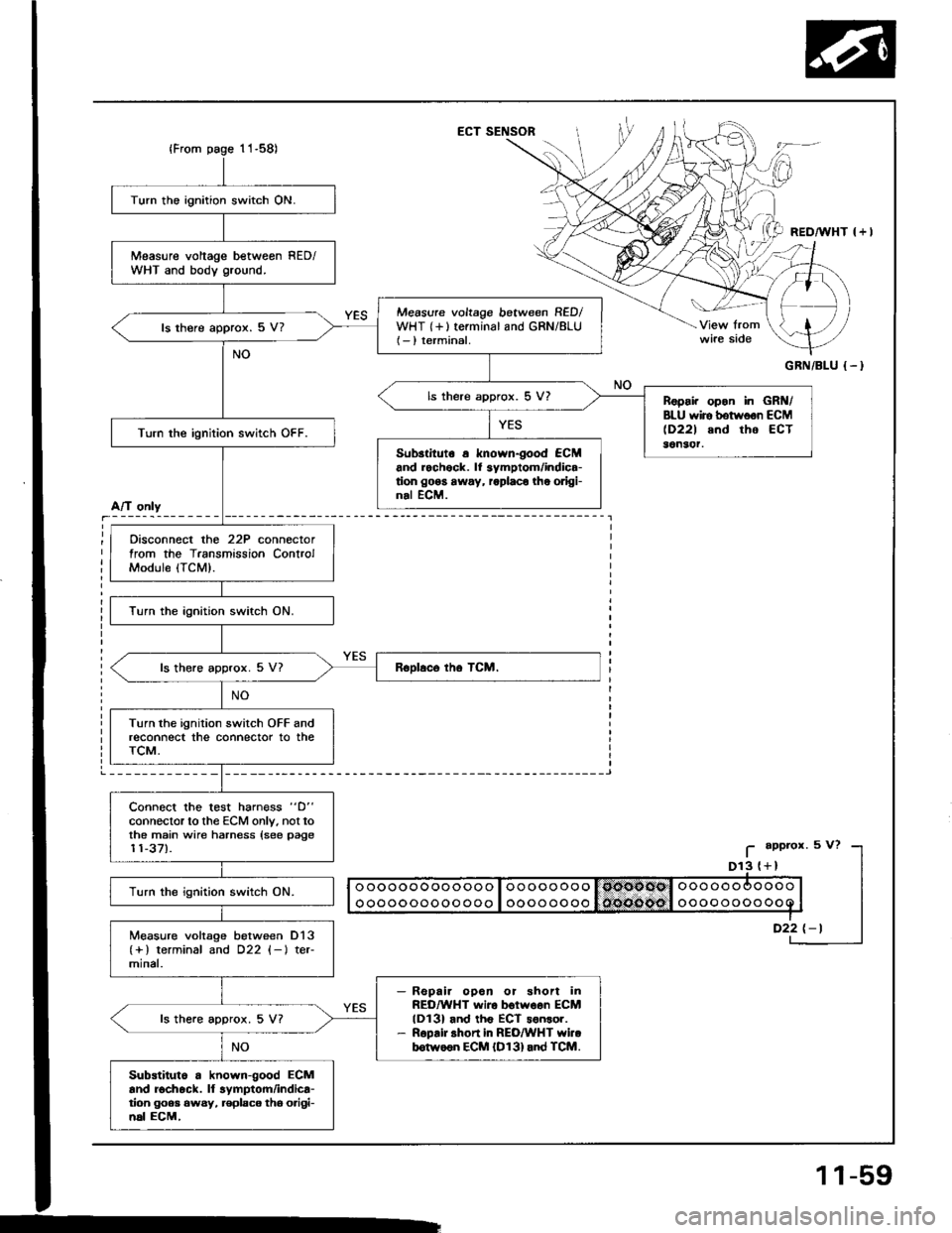
Turn the ignition switch ON.
Measure voltage betweon RED/WHT and body ground.
Measure voltage between RED/WHT {+}terminal and GRN/8LU(- ) terminal.ls there approx. 5 V?
ls there approx. 5 V?Ropai. opon in GRN/BLU wiro botwoon ECM(D221 and tho ECT36n3('r.Turn the ignition switch OFF.
Sub3tituto a known-good €CMand rochock. lf 3ymptom/indica-tion go6s away, roplaco the odgi-nal ECM.
Oisconnect the 22P connectortrom the Transmission ControlModule (TCM).
Turn the ignition switch ON.
ls there approx. 5 V7
Turn the ignition switch OFF andreconnect the connector to theTCM.
Connect the test harn€ss "D"
connector to the ECM only. not tothe main wire harness {see page11-37).
Turn the ignition switch ON.
Measure voltage between D13(+) terminal and D22 (-l ter-mlnal.
Repair opoa or shon inREO/WHT wiro botwoen ECMlDl3l and th6 ECT sonsor.R6pair shon in REO/WHT YYi..b6tw66n ECM {D131and TCM.
ls the.e approx. 5 V?
Substiluto a known-good ECMand rochock. ll lymptom/indica-tion goea 6wsy, replaco tho o.igi-n6l ECM,
A/T only
I
_i
11-59
Page 252 of 1413
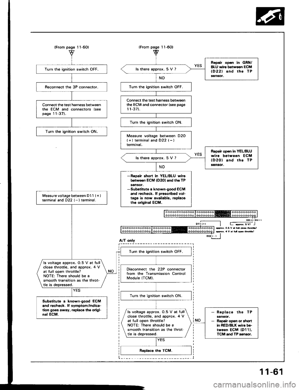
(From1 1-60){From
A/T only
Turn the ignition switch OFF.
Connect the test harness betweenthe ECM and connectors (seepage 11-37l-.
Turn the ignilion switch ON.
Measure voltage between D1 1 {+ )terminal and 022 (- I terminal.
Turn the ignition switch OFF.
ls voltage approx. O.5 V at lullclose throtlle. and approx. 4 vat full open throttle?NOTE: There should be asmooth transition as the throt-tle is depressed.
Disconnect the 22P connectorfrom the Transmission ControlModule (TCM).
lurn the ignition switch ON.
Substitute a known-good ECMand roch6ck. ll symptom/indica-tion 9063 away, roplaco th6 origi-nal ECM.- Replaco tho TPaonsoa,- Repai. opon or ahonin RED/BLK wir. b€-twoon ECM lDl1l,TCM 6nd TP sonsor.
ls voltage approx. 0.5 V ar fullclose throttle, and approx. 4 Vat tull open throttle?NOTE: There should be asmooth transition as the throt'tle is deprossod.
page 1 1-60)
Repsir op.n in GRN/8LU wii6 botwoon ECMlD22l snd tho TPaenaot.
ls there approx. 5 V ?
Turn the ignition switch OFF.
Connect the test hamess betweenthe ECM and connector {see page11-37).
Turn the ignition switch ON.
Measure voltage between D2O{+) terminsl and D22 {-}termtnal,
Ropoi. open in YEL/BLUwire bgtween ECM{D20} and rho TP30naot.
ls there approx. 5 V 7
-ReDai. ahort in YEL/BLU wiroborwoon ECM (D2Ol and tho TPson30t.-Sub3tituto a known-good ECM6nd rochock. It prcacribod vol-t6go is now availablo, roplacoth6 original ECM.
Fr. o.5 v n tua .b drdn ?
11-61
Page 258 of 1413
PGM-FI System
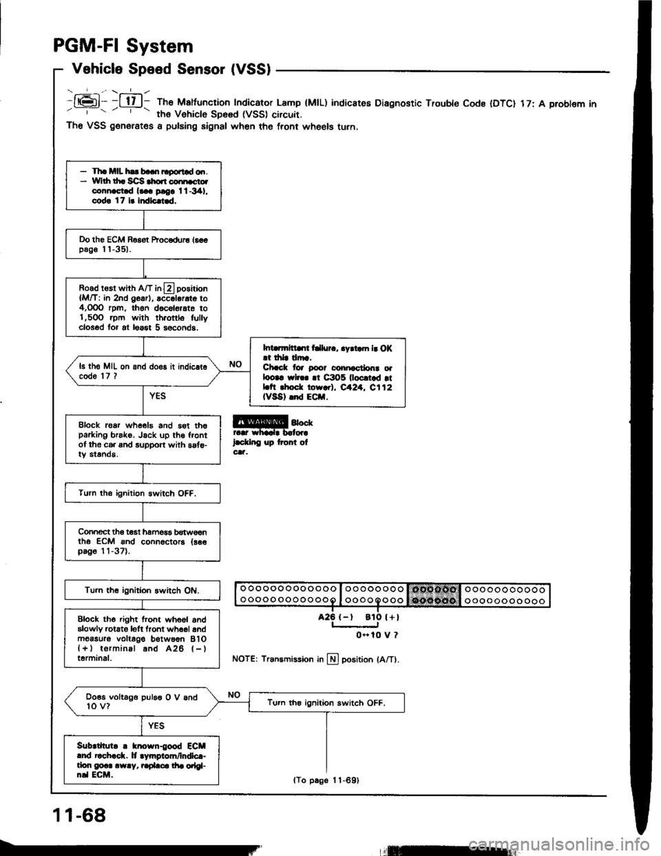
Vehicle Speed Sensor (VSS)
- _-_f_-., \-=1_ -
It6l- -l tl l- The Maltuncrion Indicator Lamp (MtL)' ths Vehiclo SD6sd (VSS) circuit.
indicateE Diagnostic Trouble Code IDTC) 17: A problem in
a25 {-t
The VSS generates a pulsing signal when the front wheels turn.
@4""rr.r whadr b.lor.
l.d.lnC up tront olcat,
NOTE: Transmission in llj position lA/Tl.
- Tha mll hs b..n ltgortld o.r.* Yvlrh th. Sc]S $o.r coi[cto.connast.d l... ploa I l -341,
cod! 17 i. Indlc.i.d.
Do the ECM Basot Procodur6 16€€pag€ I I -351.
Road rosr whh A/T in13 positaon
{M/T: in 2nd O6ar), accol6rat6 to4,OOO rpm, thon d6c6l6,ate to1,5OO .pm with th.ottlo fullyclosod tor at loast 5 s6conds.
Int rmltllrt t llur., .yrtam b O|(.t drlr drr.Chcct lor poor conicctlon! oalootc wl... !t C3O5 0ocrtad rtLtt rhod. torr.l, eA24. C112IVSA) .nd ECil.
ls th6 MIL on and doos it indic.t6code 'l7 ?
Block roar whe€19 and 5st th6parking brsko. Jsck up th€ f.ontof the c6. and support with saf€-iy standa.
Turn the ignition Bwitch OFF.
Connect tho t€st hamos3 b€tw€€ntho ECM ond connoctora {as€pag6 11-37).
Tu.n th€ ignitioh switch ON.
Block the .ight lront whoel andalowly rctato loft tront wh6ol andm6asur6 voltago b€twoon BlO{+) torminal and A26 l-}terminal.
Doss voltago puleo O V and10 v?Tu.n th€ ignition switch OFF.
Sub|tllul. ! knosn{ood ECMlnd r!ch.ck. lt .Vmgiom/lndlc.-tlon g@.. .w.y, r.pLca di. orlgl-n.l ECM.
ato l+l
0- 10 V ?
11-68
lTo p6ge 1 1-691
llEur
Page 265 of 1413
PGM-FI System
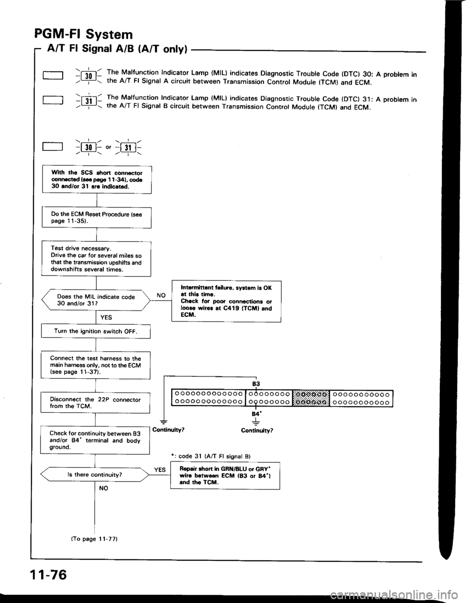
A/T Fl Signal A/B (A/T only)
\[l0l- The Maltunction Indicaror Lamp (MlL) indicates Diagnostic Trouble Code (DTC) 30: A problem In-L= the A/T Fl Signat A circuit between Transmission Control Module (TCMI and ECM.
tItil- The Malfuncrion Indicaror Lamp {MlL) indicates Diagnostic Trouble Code {DTCI 31: A problem In-Li!- the A/T Fl Signal B circuit between Transmission Controt Module (TCM) and ECM.
\.__r_/ \.__r_/-l 30 l- o'-l 3t l------ /----\
84'
+ulty? Continuity?
r: code 31 1A/T Fl signal Bl
11-76
Wlth tho SCS ahon connocrolconi|ocd {!o. p.g. 'l 1 -341, codo3O and/or 31 ars indicltod.
Oo ths ECM Resot Proceduro {seepag€ 'l 1-35).
Test drive necessary.Drive the car lor several miles sothat the transmission uDshifts anddownshilts several times.
Intormittant tsilu.o, sy3tem iB OKat thir tima,Chack lor poor connactions otl.ro!€ wiror at C419 (TCM] andECM.
Does the MIL indicare code30 and/or 31?
Turn the ignition switch OFF.
Connect the test harness to th€main harness only, not to the ECM(see p8go l'l-37).
Disconnect the 22P connectorfrom the TCM.
Check lor continuity between B3andlor 84' terminal and bodygrouno.
Ropair lhon in GRN/8LU or GRY'wiro b6twoon ECM (83 or 84'land tho TCM.
(To page 11-77)
Page 277 of 1413
ldle Control System
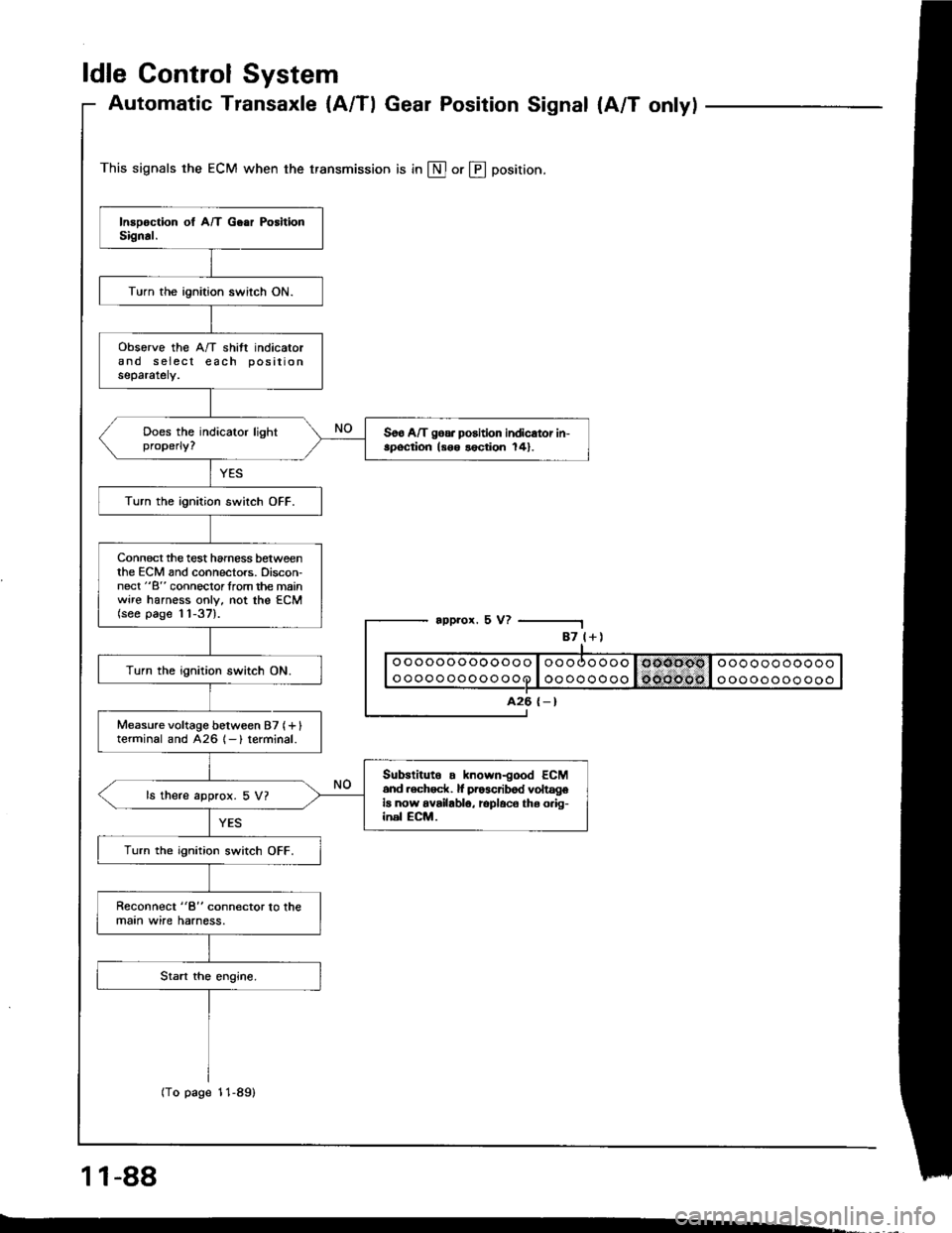
Automatic Transaxle {A/Tl Gear Position Signal {A/T onlyl
This signals the ECM when the transmission is in @ or @ position.
appror. 5 V?
1 1-88
-.
87 l+)
ooooooooooooo
oooooooooooo
A26 {-}
Turn the ignition switch ON.
obsorve the A/T shift indicatorand s eiecl each positionseparately.
Soo A/T goa. position indicator in-spoqtion ls6o lection 141.
Turn the ignition switch OFF.
Connect the test hamess betweenthe ECM and connectors. Discon-nect "B" connoclorlrom the mainwire harness only, not the ECM(see page 11-37).
Turn the ignition switch ON.
Measure voltage between 87 (+ Iterminal and 426 1- ) terminal.
Subslituto . known-good ECM6nd .ech6ck. lf pr63cribod voltageia now availablo, rcplaco ths o.ig-inel ECM.
ls there approx. 5 V?
Turn the ignition switch OFF.
Reconnect "8" connector lo lhemaan wire harness.
(To page 11-89)
Page 278 of 1413
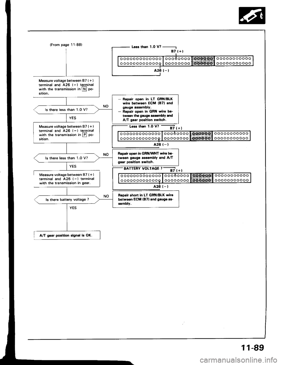
Measure voltage between 87l+)terminal and A26 (-) teJqrinalwith the transmission in Lryl po-
sataon.
Measure voltage between B7l+)terminal and A26 l-) terminalwith the transmission in gear.
{From page 11-88)
A/T goat position signal b OK.
L63r than 1,0 V? -
Lo.s rhln 1.0 v? --ii t + t
o oooooo oooooo I oooooooo I OOnPsOl oooooo ooooo
ooooo ooooo ooo I oooooooo lQcosito I ooooooooooo
A26 (- )
BATTERY VOLTAGE ? --;; { + I
87 l+)
ooooooooooooo
oooooooooooo
426 (- )
Ropair open in LT GRN/BLKwir. botwoon ECM lB7) andgaugo as!€mbly.- Rspalr opon in GR wito b.-twoon tho gaug6 a$ombly lndA/T goar position .witch.
ls there less than 1.0 V?
Measure voltage between 87 (+ Iterminal and A26 (-) reJqrinalwith the transmission in lPl po-
sition.
Reprir open in GRNMHT wi.r bg-twoon gaugo ssrombly and A/Tgoar poritlon 3witch.ls there less than 1.0 V?
R6oai. short in LT Git{/BLK wirebotwo6n ECM (B7l and gaugo ar-aombly.ls there battery voltage ?
A26 t- )
11-89
Page 301 of 1413
![HONDA INTEGRA 1994 4.G Owners Manual Fuel Supply System
PGM-Fl Main Relay (contdl
BLU
BLU/wHt
Bt-xNOTE:. M/T: Clutch pedal mustbe depressed.. A/T: Transmission in
N or E] position.
BLK/ YEL/YEL BLK
Tloubloshooting
{To page 11 113}
- Eng HONDA INTEGRA 1994 4.G Owners Manual Fuel Supply System
PGM-Fl Main Relay (contdl
BLU
BLU/wHt
Bt-xNOTE:. M/T: Clutch pedal mustbe depressed.. A/T: Transmission in
N or E] position.
BLK/ YEL/YEL BLK
Tloubloshooting
{To page 11 113}
- Eng](/img/13/6067/w960_6067-300.png)
Fuel Supply System
PGM-Fl Main Relay (cont'dl
BLU
BLU/wHt
Bt-xNOTE:. M/T: Clutch pedal mustbe depressed.. A/T: Transmission in
N or E] position.
BLK/ YEL/YEL BLK
Tloubloshooting
{To page 11 113}
- Engino will not sran.- Inspection oI PGM-FI main re-lay and rolay ha.n6!a.
Check lor continuitv between BLKterminal @ and body ground.
Rapair open in BLK wire botwoonPGM-FI main.el6y and GIO'l llo-catod at thormostot housingl.
Measure the voltage betweenYELMHT terminal @ and bodyground.- Roplaco th. ECU IECMI(15 Allus6 in tho under-hood fu!o/r6-lay box.- Ropair opan or short in theYEL/WHT wil6 botwosn thePGM-FI main rolay and the ECU
{EcMl 115 A} luso.
ls there battery voltage?
Turn the ignition switch ON.
Measure the voltage betweenBLK/YEL terminal @ and bodyground.- Reolac. ths No. 24 ACG {ALT}{lcl {15 A:81881 6ngino, 20A: Bl8Cl engin6) tuse in thoundor-dash fuso/rolaY box.- Ropaii op6n or rhon in thoBLK/YEL wiro botwoen thoPGM-FI main ielay and th€ No.24 ACG {ALT) flG} {'�15 A:818Bi ongine, 20 A: 818Cionginol fuso.Turn the ignition switch to theSTART position.
Measure the voltage betweenBLUMHT terminsl @ and bodyground.
- Replaco the l\lo. 18 STARTERSIGNAL {7.5 A} fuso in thoundor-dash fuaa/rolay box.- R6pai. open or short in thoBLU/WHT wire botweon thsPGM-FI main relay and tho No.1A STARTER SIGNAL I7.5 AIluse.
11-112