bulb HONDA INTEGRA 1994 4.G Owner's Guide
[x] Cancel search | Manufacturer: HONDA, Model Year: 1994, Model line: INTEGRA, Model: HONDA INTEGRA 1994 4.GPages: 1413, PDF Size: 37.94 MB
Page 1311 of 1413
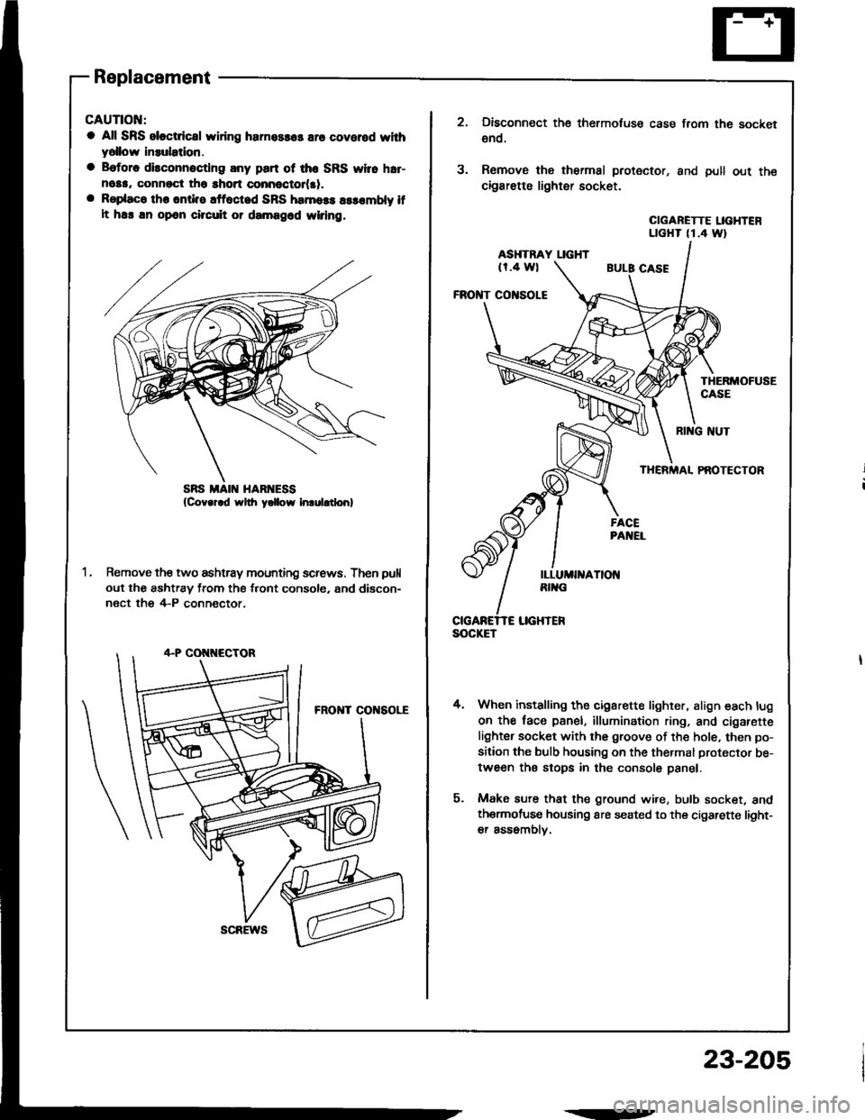
Replacement
CAUTIOI{:
a All SRS sloctdcal wiring harnossas are covered whhyollow insulatlon.
a B.tore disconnoctlng any part ot the SRS yyi16 h.r-nosa, connrct tho short connoctot(al.a Rsplaco th. onti.e !ffoct.d SRS hamoss a$ombly lfIt ha! an opon cilcuit or damagod wiring.
Remove the two ashtray mounting screws. Then pull
out the ashtray from the front console, and discon-
nect the 4-P conn€ctor,
scREws
.--
23-205
SOCKET
3.
Disconnect the thermotuse case from the socket
€no.
Remove the thermal protector. and pull out the
cigarette lighter socket.
CIGARETTE LIGHTENLTGHT (1.4 Wt
ASHTRAY LIGHT(r.4 wl
FROI{T CO|{SOLE
THERMOFUSECASE
4.
RI G NUT
THERMAL PAOTECTOR
When installing the cigarette lighter, align each lug
on the face panel, illumination ring, and cigarefte
lighter socket with the groove of the hole, then po-
sition the bulb housing on the thermal protector be-
tween the stops in the console panel.
Make sure that the ground wire, bulb socket, andthermofuse housing are seated to the cigarette light-
er assomblv.
Page 1315 of 1413
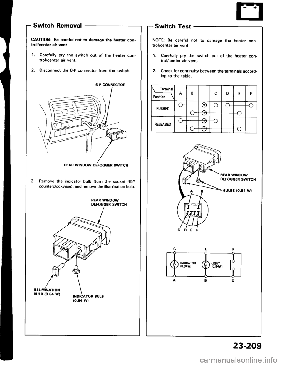
Switch Removal
CAUTION: Be caroful not to damags the hoator con-tlol/centel ail vent.
1, Carefully pry the switch out of the heater con-tfol/center air vent.
2. Disconnect the 6-P connecto, from the switch.
Remove the indicator bulb (turn the socket 45o
counterclockwise), and remove the illumination bulb.
REAR WINDOWDEFOGGER SWITCH
Switch Test
NOTE: Be caretul not to damage the heate. con-trol/center air vent.
1. Carefully pry the switch out of the heater con-
trol/center air vent.
2. Check tor continuity between the terminals acco.d-
ing to the table.
Torminal
P*il*__\IDF
PUSHEDo--oo-_o
o-
\../
-\-o
RETEASEDo-/\
o-
\:,,t
/:\\7
REAR WINDOW DEFOGGER SWITCH
[-4
I
) ll:g'", li'T
to.a4 wt
23-209
Page 1348 of 1413
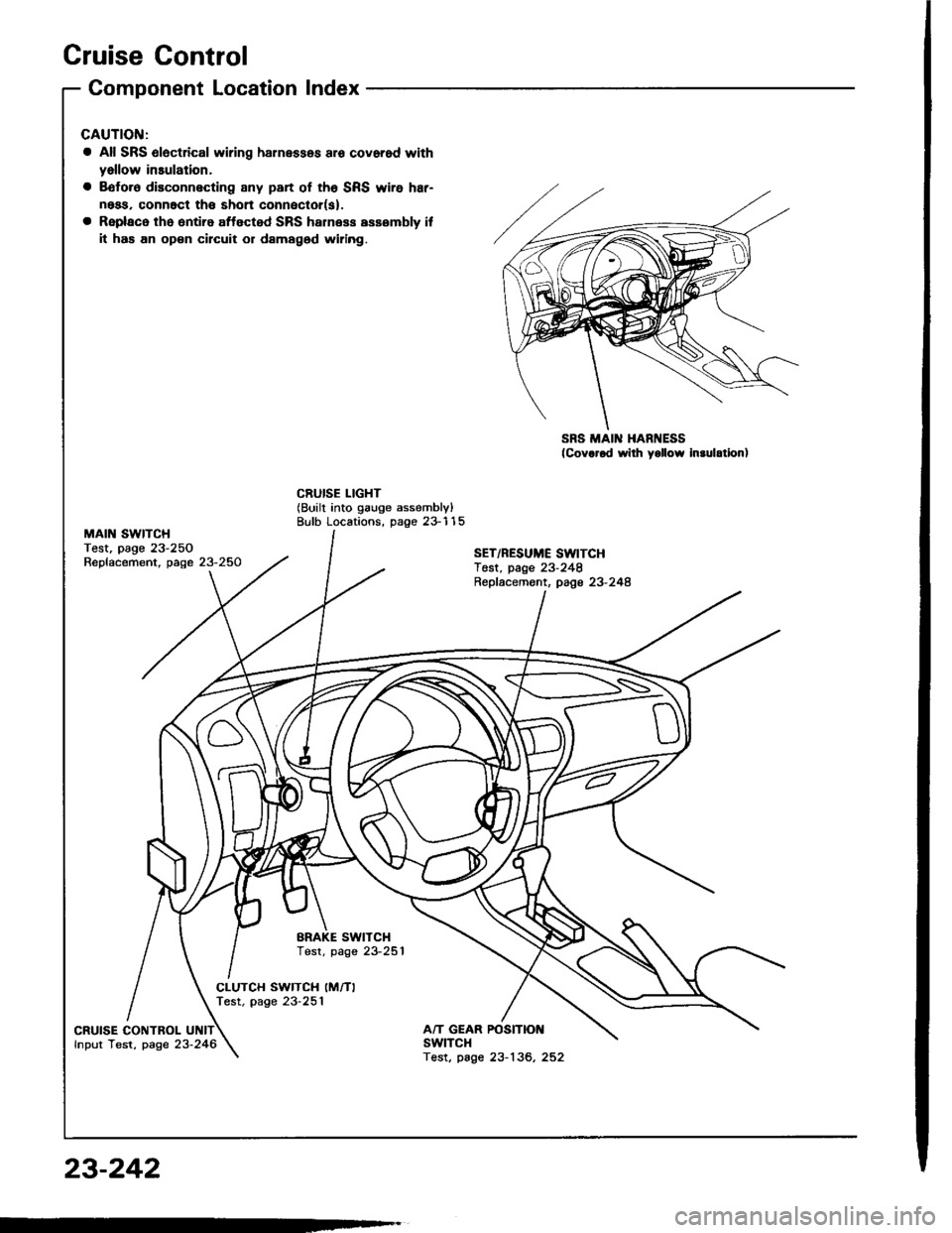
Cruise Control
MAIN SWITCHTest, page 23-250Replacement, page 23-250
Component Location Index
a All SRS 6l6ctrical wiring harnessos aro covorod with
yallow insulation,
a Bofo.6 disconnecting any part of th6 SRS wire har-
ness, connoct th€ shon conneclor(s).
a Replaco the ontiro affected SRS halness assombly if
it has an op€n circuit or damagod widng.
SRS MAIN HARNESS(Cov.rod wilh yollow In.ulation)
CRUISE LIGHT(Built into gauge assembly)Bulb Locations, page 23-115
SET/RESUME SWITCHTest. page 23-248Repfacemont, page 23-248
BRAKE SWITCHTest. page 23-251
CLUTCH SWITCH (M/TI
Test, page 23-251
CRUISE CONTROLfnput Test, page 23-246A/T GEAR POSITIOI{swtTcHTest, page 23-136, 252
23-242
Page 1353 of 1413
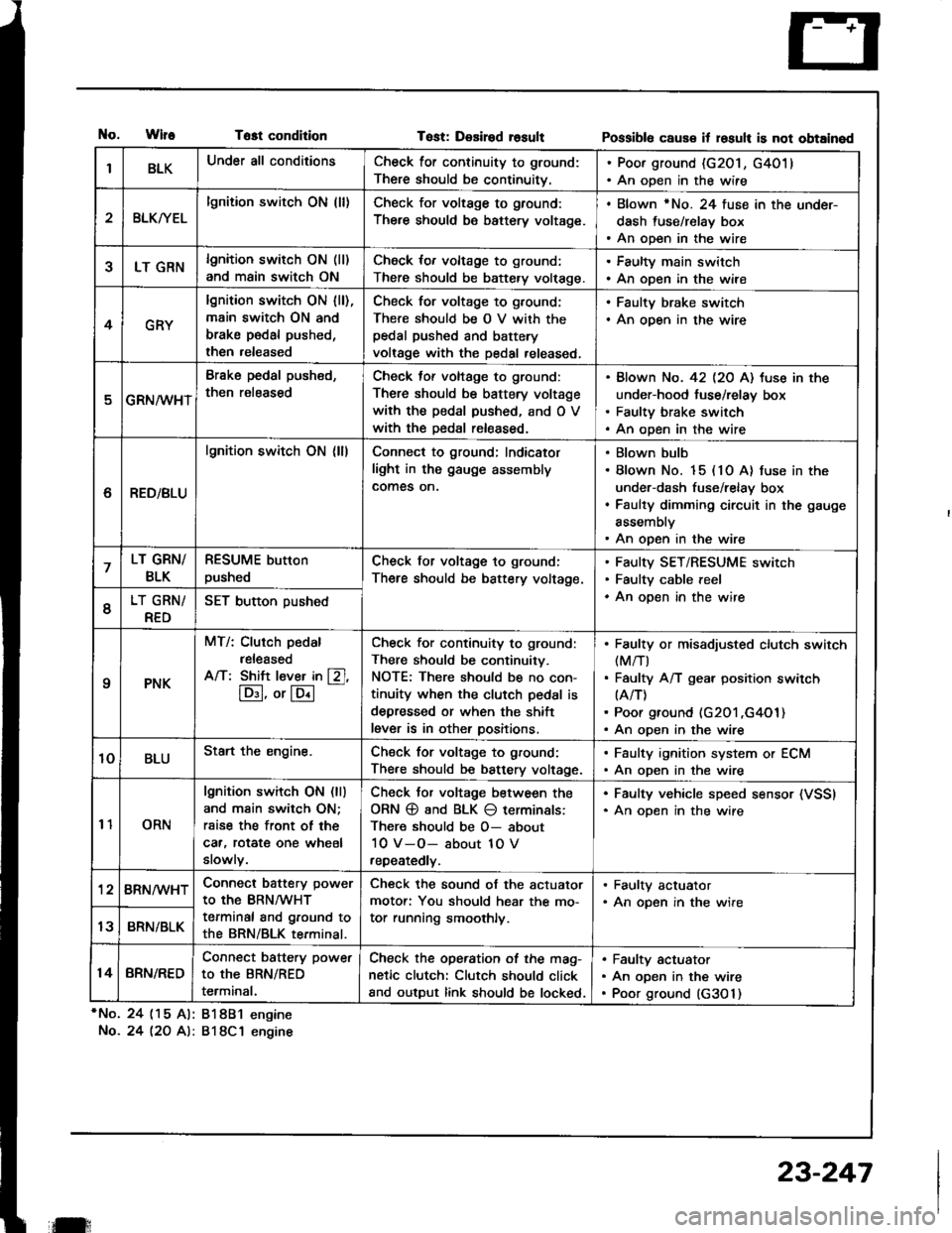
tlo.WlfeTost condition
*No. 24 (15 Al: 81881 engine
No.24 l2O A): 818C1 engine
Tost: Desired rosultPossibl6 caus€ it losult is not obtained
IBLKUnder all conditionsCheck for continuity to ground:
There should be continuitv.
. Poor ground (G201, G4011. An open in the wire
2BLKryEL
lgnition switch ON (ll)Check for voltage to ground:
There should be battery voltage.
. Blown rNo. 24 fuse in the under-
dash fuse/relay box. An open in the wire
5LT GRNlgnition switch ON (ll)
and main switch ON
Check for voltage to ground:
There should be battery volt€ge.
. Faulty main switch. An open in the wire
4GRY
lgnition switch ON lll),main switch ON and
brake pedal pushed,
then released
Check for voltage to g,ound;
There should be O V with thepedal pushed and battery
voltage with the pedal released,
. Faulty brake switch. An open in the wire
GRN/wHT
Brake pedal push€d,
then r€leased
Check tof voltage to ground:
There should be battery voltage
with the pedal pushed, and O V
with the Dedal released.
Blown No. 42 l2O Al tuse in the
under-hood fuse/relay box
Faulty brake switch
An open in the wire
6RED/BLU
lgnition switch ON (ll)Connect to ground; Indicator
light in the gauge assembly
comes on.
Blown bulb
Blown No. 15 (10 A) fuse in the
under-dash fuse/relay box
Faulty dimming circuit in the gauge
assembly
An open in the wire
7LT GRN/
BLK
RESUME button
pushedCheck for voltage to ground:
There should be battery voltage.
Faulty SET/RESUME switch
Faulty cable reel
An open in the wire6LT GRN/
RED
SET button pushed
qPNK
MT/: Clurch pedal
released
A/T: Shift l€ver in [Zl,
lD:I, or lE.l
-
Check for continuity to ground:
There should be continuity.
NOTE: There should be no con-
tinuity when the clutch pedal is
depressed or when the shift
lever is in other positions.
Faulty or misadiusted clutch switch(M/T)
Faulty A/T gear position switch(A/T)
Poor ground (G201 ,G4O1)An open in the wire
10BLUStart the engine.Chsck for voltage to ground:
There should be battery voltage.
. Faulty ignition system or ECM. An open in the wire
11ORN
lgnition switch ON (ll)
and main switch ON;
rsise the front of the
car, rotat€ one wheel
slowly.
Check Jor voltage between the
ORN @ and BLK O terminals:
There should be O- about
10 V-O- about 1O V
repeatedly.
. Faulty vehicle speed sensor (VSSI. An oDen in the wire
'128RN/WHTConnect battery power
to the BRN/WHT
terminal and ground to
the BRN/BLK terminal.
Check the sound of the actuator
motor: You should hear the mo-
tor running smoothly.
. Faulty actuator. An opsn in the wire
13BRN/BLK
14BRN/RED
Connect battery power
to the BRN/RED
terminal.
Check the operation of the mag-
netic clutch: Clutch should click
and output link should be locked.
Faulty actuator
An open in the wire
Poor ground (G3O 1)
il:
23-247
Page 1384 of 1413
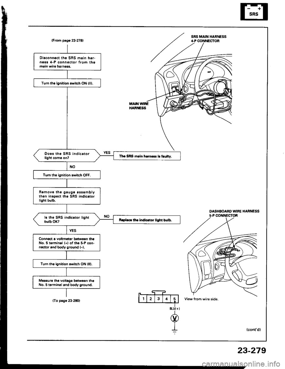
SRS MAIN HABNESS(From plgr 23.27E1
DASHBOARD WIFE HARNESS5-P CONNECTOR
8tU{ +
@
I:
Disconnoct tho SRS m.in h6,-ng88 {-P conn6clor f,om thomrin wiao harn6$.
Tum lhq ignition switch ON (lll.
Doo3 tho SRS indic.torlight com6 on?Th. SRS rnlin h..n... i.t ulty.
Tu.n tho ignition switch OFF.
Romovo tho g!u0c !ss.mblyth6n inrpoct ths SBS indicatorlight bulb.
Raplaca lh. indlc.toi llOht birlb.
Connoct ! voltmotoa bdwoln thrNo. 5 lormin.l (+) of tho 5-P con-noctor rnd body ground (-).
Turn the ignition switch ON (ll).
Moaauro tha voltrgo bolwcon thaNo. 5 termin.land body g.ound.
MAIN VNREHARNESS
(To p.go 2+280)
23-279