Remove trans HONDA INTEGRA 1994 4.G Service Manual
[x] Cancel search | Manufacturer: HONDA, Model Year: 1994, Model line: INTEGRA, Model: HONDA INTEGRA 1994 4.GPages: 1413, PDF Size: 37.94 MB
Page 588 of 1413
Differential (AutomaticTransmission)
Backlash InspectionBearing Replacement
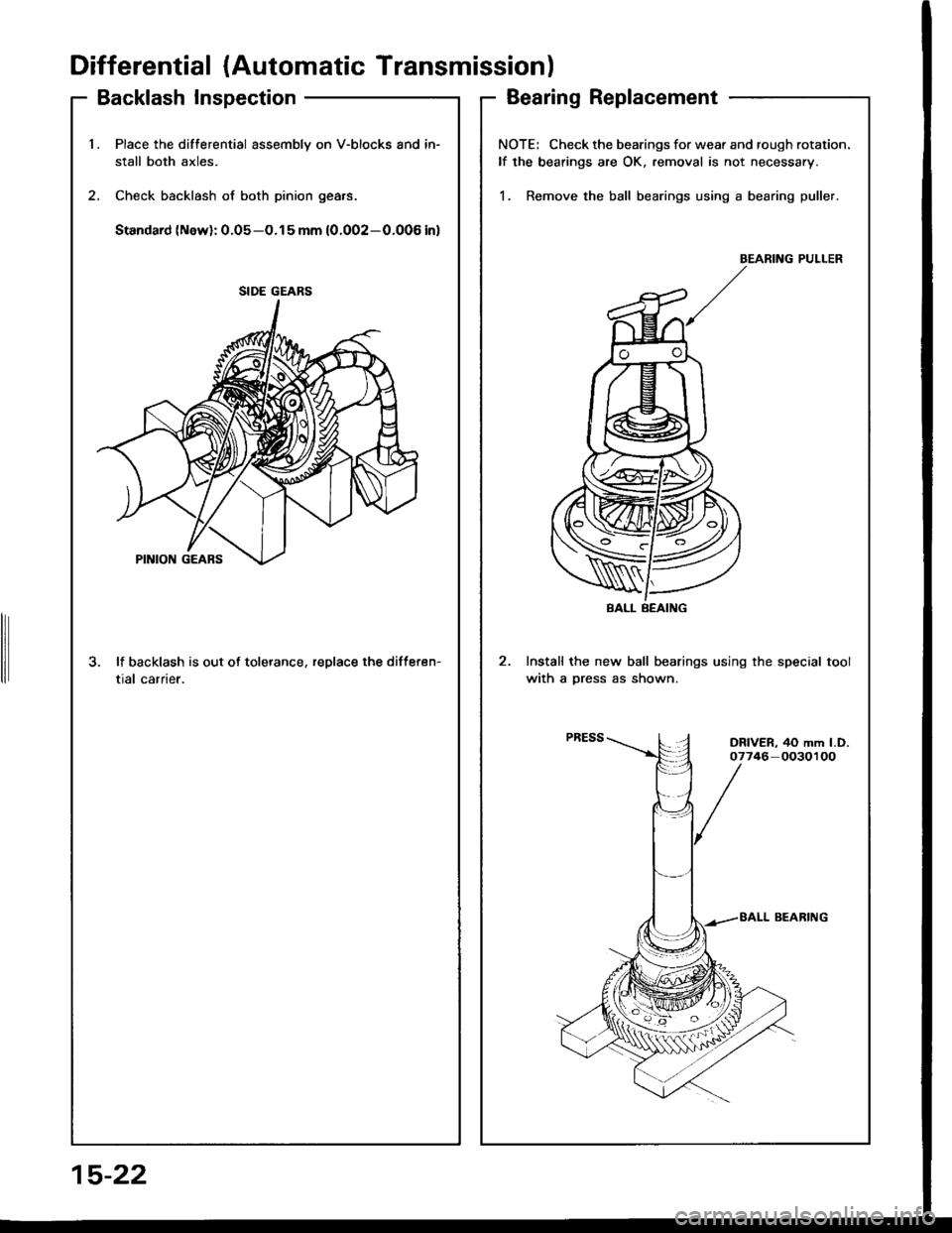
1.Place the differential assembly on V-blocks and in-
stall both axles.
Check backlash of both pinion gears.
Standard (New): 0.05-O.15 mm (0.002-0.006 inl
3. lf backlash is out of tolerance, replace the differen-
tial carrier.
SIDE GEARS
NOTE: Check the bearings for wear and rough rotation.
lf the bearings are OK, removal is not necessary.
1. Remove the ball bearings using a bearing puller.
BEARING PULLER
Install the new ball bearings using the special tool
with a Dress as shown.
BALL BEAING
DRIVER, 40 mm l.D.07746 0030100
15-22
Page 590 of 1413
Differential (Automatic Transmissionl
Oil Seal Removal
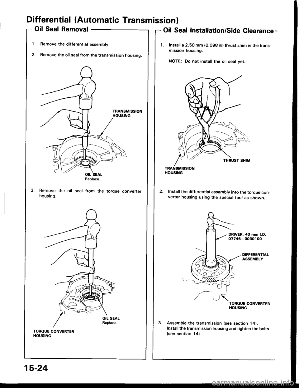
Remove the differential assembly.
Remove the oil seal from the transmission housino.
TRAt{SMtSStONHOUSING
1.
2.
Oil Seal Installation/Side Clearance-
1. lnstalla 2.50 mm (O.O98 in) thrust shim in the rrans-
mission housing.
NOTE: Do not install the oil seal yet.
TRANSMISSIOHOUSING
Install the differential assembly into the torque con_v€ner housing using the special tool as shown.
DRIVER, 40 mm l.D.07746-OO30100
DIFFERENTIALASSEMBLY
/-l
TOROUE CONVERTERHOUSING
Assemble the transmission (see section 14).
Installthe transmission housing and tighten the bolts(see section 14).
OIL SEALReplace.
seal from therorque convener
TOROUE CONVERTERHOUSING
15-24
Page 591 of 1413
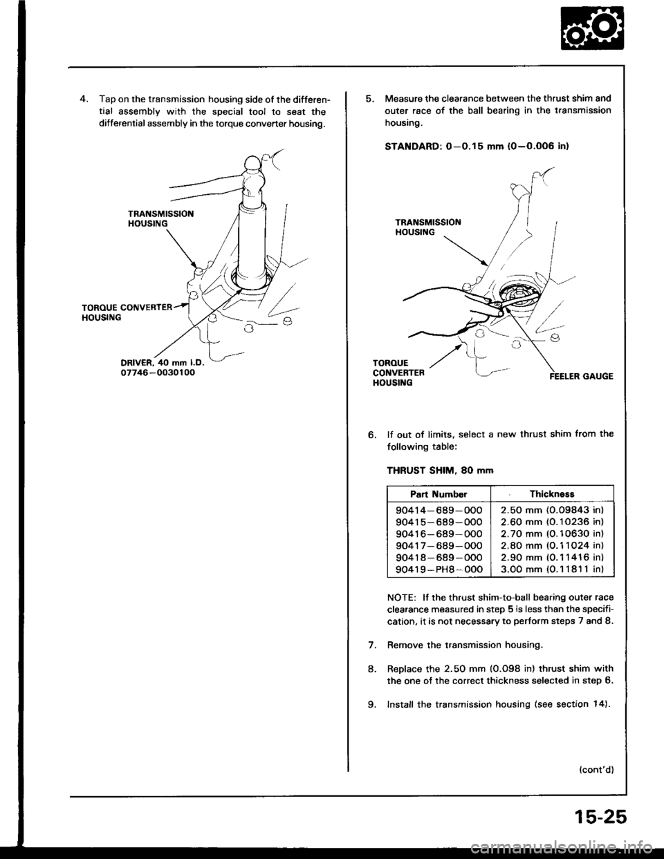
Tap on the transmission housing side of the differen-
tial assembly with the special tool to seat the
dilferential assembly in the torque converter housing.
Measure the clearance between the thrust shim and
outer race of the ball bearing in the t.ansmission
housing.
STANDARD: O-0.15 mm {0-O.OO6 in}
lf out of limits, select a new thrust shim from the
following table:
THFUST SHIM, 80 mm
NOTE: It the thrust shim-to-ball bearing outer race
clearance measured in step 5 is less than the specifi-
cation, it is not necessa.y to pertorm steps 7 and 8.
Remove the transmission housing.
ReDlace the 2.50 mm (0.098 in) thrust shim with
the one oJ the correct thickness selected in step 6.
Install the transmission housing (see section 14).
(cont'd)
8.
Pan Numb€rThickness
90414-689-OOO
90415-689-OOO
90416-689-000
9041 7- 689-000
904r 8-689-OOO
90419-PH8-OOO
2.50 mm (O.O9843 in)
2.60 mm {0. I 0236 in)
2.70 mm (O.10630 in)
2.8O mm (O. 1 1O24 in)
2.90 mm (0.1 1416 in)
3.OOmm{O.11811in)
9.
15-25
Page 595 of 1413
Driveshafts
Inspection
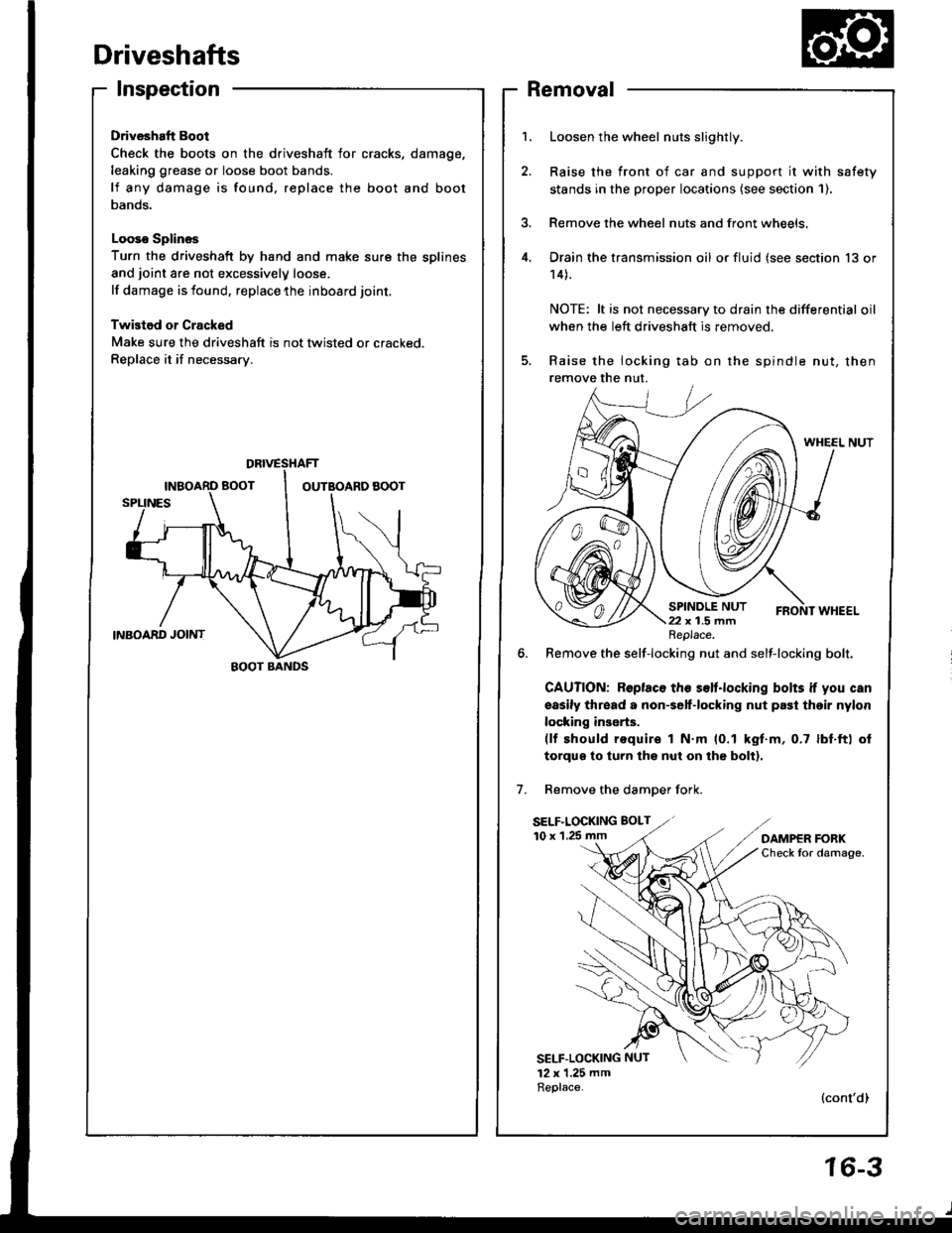
Driveshaft Boot
Check the boots on the driveshaft for cracks,
leaking grease or loose boot bands.
lf any damage is found, replace the boot
Danos.
Looso Splines
Turn the driveshaft by hand and make sure the splines
and joint are not excessivelV loose.
lf damage is found, replace the inboard joint,
Twistod or Cracked
Make sure the driveshaft is not twisted or cracked.
Replace it if necessarv.
damage,
and boot
Removal
Loosen the wheel nuts slightly.
Raise the front of car and support it with safety
stands in the proper locataons (see section 1),
Remove the wheel nuts and front wheels,
Drain the transmission oil or fluid (see section 13 or
14).
NOTE: lt is not necessary to drain the differential oil
when the left driveshaft is removed.
Raise the locking tab on the spindle nut, then
remove the nut.
WHEEL NUT
6. Remove the self-locking nut and self-locking bolt.
GAUTION: Roplaco th€ s€lt.locking bolts if you can
sasily thread a non€elf-locking nut prst thoir nylon
locking inserts.(lf should require I N.m (0.1 kgt.m, 0.7 lbf.ft) ol
torqus to turn lhs nut on the bolt).
Remove the damDer fork.
SELF.LOCKING BOLT
10 x 1.25 mm
SELF-LOCKING NUT
12 x 1.25 mmReplace.(cont'dl
DBIVESTIAFT
EOOT BANDS
Replace.
16-3
Page 604 of 1413
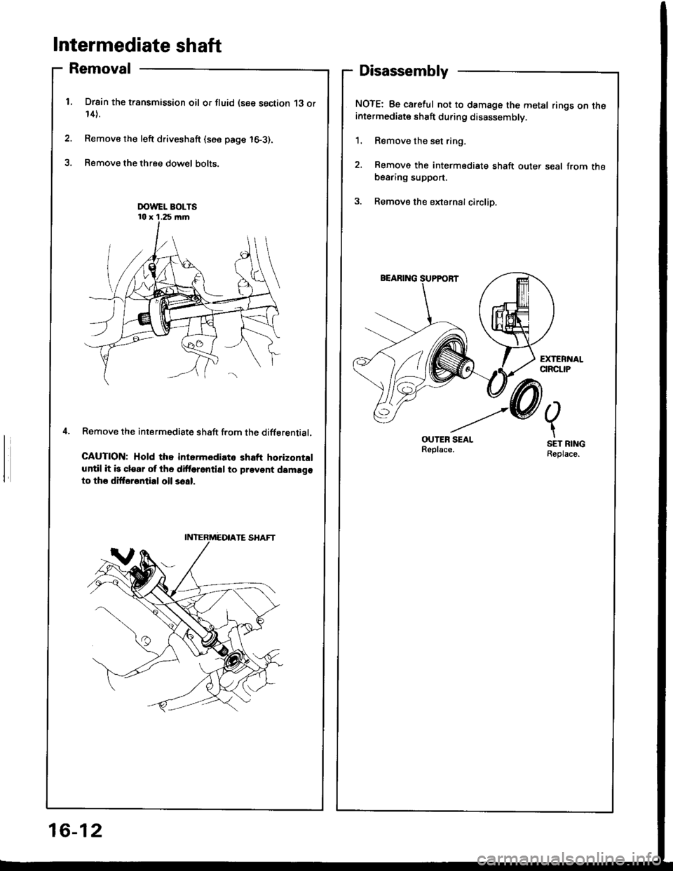
Intermediate shaft
Removal
Drsin the transmission oil or fluid (see section 13 or14).
Remove the left driveshaft (see page 16-3).
Remove the three dow€l bolts.
Remove the intermediate shaft f.om the differential.
CAUTION; Hold the intormediato shaft horizontrl
until it b clear of the dittorential to prevent damago
to thr dittarontial oil so!|.
Disassembly
NOTE: Be careful not to damage the metal rings on theintermediate shaft during disassembly.
1. Remove the set ring,
2. Remove the intermediate shaft outer seal from thebearing support.
3. Remove the eldernalcirclip.
OUTEB SEALReplsce.
2.
t
SET RINGReplace.
16-12
Page 610 of 1413
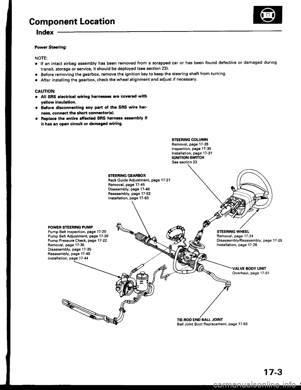
Component Location
lndex
Powar Siooring:
NOTE:
a
a
It an intact airbag ass€mbly has been r€moved from a scrapped car or has been found defective or damaged during
transit. storage or service, it should be doploy€d (see section 23).
Before removing tho gearbox, remove ths ignition key to keep the steering shaft Jrom turning.
After installing the gearbox, check ths whe€l alignment and adiust if necessary.
CAUTION:
. All SRS aloctricll wiring h!m!|$a rrc covcred with
yrllow in3uhtion.
. 8€for€ disconnocling lny ptrt ol thc SRS wiro h!r'
ne*r, connect thc lhort conncctor{3l.
. Rcplsce lhc ontira ttfact d SRS harnccc a$embly il
it hs3 !n oprn circuh 01 dtm!9.d wiring.
SIEERING COLUiINRemoval, page 17-28Inspection, pago 17-30Installation, p6ge 17-31rcNMON SwlTCHSee s6ction 23
STEERII{G GEARBOXRack Guide Adjustment, pag.11-21
Removal, pags 17-45Diossombly, page 17-{8Bea65€mbly, page 17-53Installation, page 17-63
POWEN STEERING PUMPPump Beft Inspoction. page 17-2OPump Eeft Adjustm6nl, pago 17-2OPump Pressurg Ch€ck, page 17-22Removai, p6go 17-35Disassembly, p3gs 17-35Reassombly, psge l7-40lnstallation, page 17-44
STEERING WHEELRemoval. page 17-24Oisassembly/Reassembly, pageInstallation, page 17-2617-25
TIE'ROD END BALL JOINTBall Joint Eoot Replacement, page 17-63
17-3
Page 632 of 1413
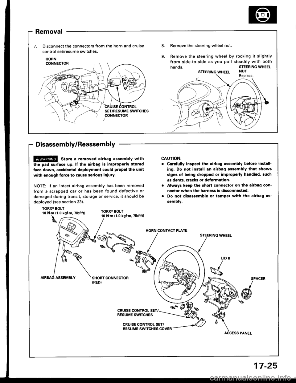
Removal
Disconnect the connectors trom the horn and cruise
control sevresume switches.
HORN
Disassembly/Reassembly
8.Remove the steering wheel nut.
Remove the steering wheel by rocking it slightly
from side-to-side as you puil steadily with both
hands.STEERING WHEEL
STEERING WHEELNUTReplace.
@ store a removed airbag assembly with
the pad 3urfacs up. lf the airbag is improperly stored
face down, accid€ntal daployment could prop€l tho unit
with enough forca to cause serious iniury.
NOTE: lf an intact airbag assembly has been removed
from a scragoed car or has been found defective or
damaged during transit. storage or service, it should be
deployed (see section 23).
TORX6 BOLT
CAUTION:
C8r€{ully inspoct ihe sirbag assombly betors install.
ing. Do not install an airbag ass6mbly that 5how3
signs ol boing dtopped or improperly handled, such
as dents, crack3 or deformation.
Always k€gp tho short connector on the aitbag con-
nector when ths harnegg i9 disconnected.
Do not disassemble or tamper with the airbag as-
sombly.
STEERING WHEEL
10 N.m {1.0 kgf m, Tlbt.ttl
t
TORX6 BOLT10 N.m {1.0 kgf.m, 7lbf.ft)
LID
\s
SPACER
/
@
CRUISE CONTROL SET/NESUME SWITCHES
CRUISE CONTROL SET/RESUME SWITCHES COVER
HORN CONTACT PI-ATE
17-25
Page 1101 of 1413
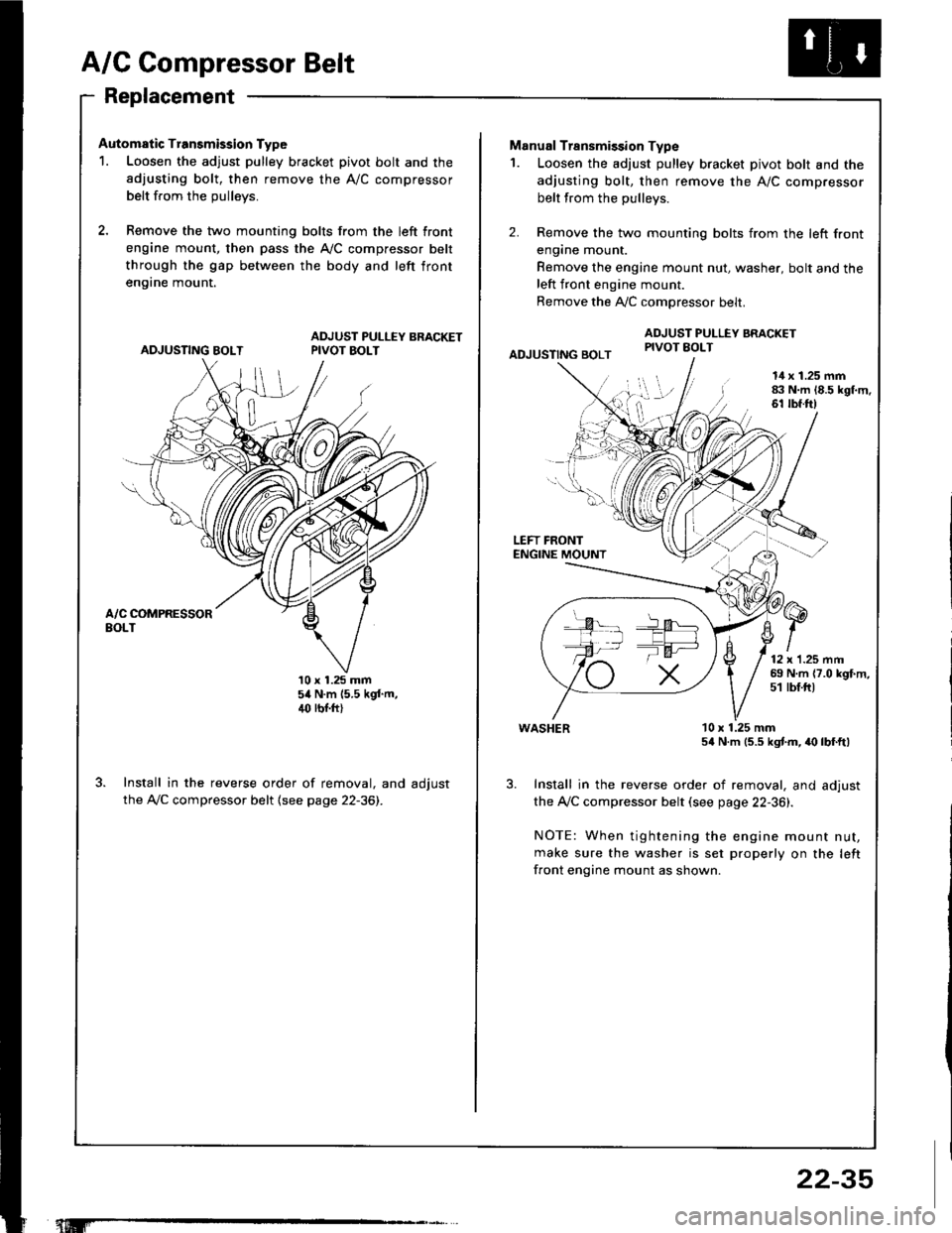
A/C Compressor Belt
Replacement
Automatic Transmission Type
1. Loosen the adjust pulley bracket pivot bolt and the
adjusting bolt, then remove the A/C compressor
belt from the oullevs.
2, Remove the two mounting bolts from the left front
engine mount, then pass the A,/C compressor belt
through the gap between the body and left front
en9rne mount.
ADJUSTING BOLTADJUST PULLEY BRACKETPIVOT BOLT
10 x 1.25 mm54 N.m (5.5 kgf.m,4(' rbr.ft)
Install in the reverse order of removal, and adjust
the A,/C compressor belt (see page 22-36).
"t.M'
22-35
-la ar-
Manual Transmission Type
1. Loosen the adjust pulley bracket pivot bolt and the
adjusting bolt, then remove the A/C compressor
belt from the pullevs.
2. Remove the two mounting bolts from the left front
engane mount.
Remove the engine mount nut, washer, bolt and theleft front engine mount.
Remove the A,./C comoressor belt.
ADJUSTING BOLT
ADJUST PULLEY BRACKETPIVOT EOLT
l!l',
I
14 x 1.25 mm83 N.m 18.5 kgl.m.61 tbf.ft)
LEFT FRONTENGINE MOUNT
12 x'1.25 mm69 N.m {7.0 kgf.m,51 tbf.ftt
WASHER
Install in the reverse order of removal, and adjust
the Ay'C compressor belt (see page 22-36).
NOTE: When tightening the engine mount nut,
make sure the washer is set properly on the left
front engine mount as shown.
10 x 1.25 mm54 N.m (5.5 kgtm, irc lbf.ft)
Page 1183 of 1413
5. Check lor 8n op€n in the BLKMHT wire circuit be-
tween the staner and ignition switch, and con-
nectors.
6. Check the ignition switch (see page 23-70).
7, On cars with automatic transmission, check the A/Tgear position switch (neutral position switchl and
connector. On cars with manualtransmission, check
the staner cut relay, clutch interlock switch, and
connectors.
NOTE: Check the No. 39 (5O A) fuse in the under-hood
fuse/relay box for the starter cut relay.
Check tor Woar and Damago:
The starter should crank the engine smoothly and stead-
ily. lf th€ startsr engages, but cranks the engine errati-
cally, remove it. Inspect the starter, drive gear, and
flywheel ring gesr for damage.
a Check the drive gear overunning clutch for binding
or slipping when the armature is rotated with the drivegear held. Replace the gesrs if damaged.
Check Cranking Voltago 8nd Current Draw:
Cranking voltage should be no less than 8.O volts.
Current draw should be no more than 360 amperes.
lf cranking voltag€ is too low, or current draw too high,
check for:
a Fully charged battery
a Open circuit in starter armature commutatot segments
a Starter armature dragging
a Shoned armature winding
a Excessive drag in engine
Chack Cranking rpm:
Engine spsod during cranking should be above 1O0 rpm.
lf spe6d is too low, ch€ck for:
a Loose battsry or starter teminals
a Excessively worn starter brushes
a Open circuit in commutator segments
a Dirty or damaged helical spline or drive gear
a Defective drive gear overrunning clutch
Chock StErtor Disongagomoni:
Press the clutch pedal allth€ way in (M/T), turn the ioni-
tion switch to "lll" and rolease to "11".
The starter drive gear should disengage from the tlywheel
ring gear. When you rolease the key.
lf the drive gear hangs up on th€ flywheel ring gear, check
for:
a Solenoid plunger and switch malfunction
a Dirty drive gear assembly or damaged overrunning
clutch
23-77
Page 1405 of 1413
Supplemental Restraint System (SRSI
Airbag Assembly Disposal (cont'd)
Connect a l2 volt batterv to the tool:
. lf the green light on the tool comes on, th€
airbag igniter circuit is d€fective and cannot
deploy the airbag. Go to Dsmag€d Airbag
Special Procedure.
. lf the red light on the tool comes on, the airbag is
ready to be deployed.
Push the tool's deployment switch. Th6 sirbag
should deploy (deployment is both highly audible
and visibls - a loud noise and raDid inflation of the
bag, followed by slow deflationl.
. lf audible/visible deploym€nt happsns and the
green light on the tool comes on, continus with
this Drocedure.
. lf the airbag doesn't deploy, yet the green light
comes ON, its igniter is dofectiv€. Go to
Damaged Airbag Special Procedure.
@ During deploym€nt, the airbsg assom-
bly can become hot enough to burn you. Wait thirty
minutes after deployment beforo touching the
assemblv.
Dispose of the complete airbag sssembly. No pan
of it can be reused. Place it in I sturdy plastic bag
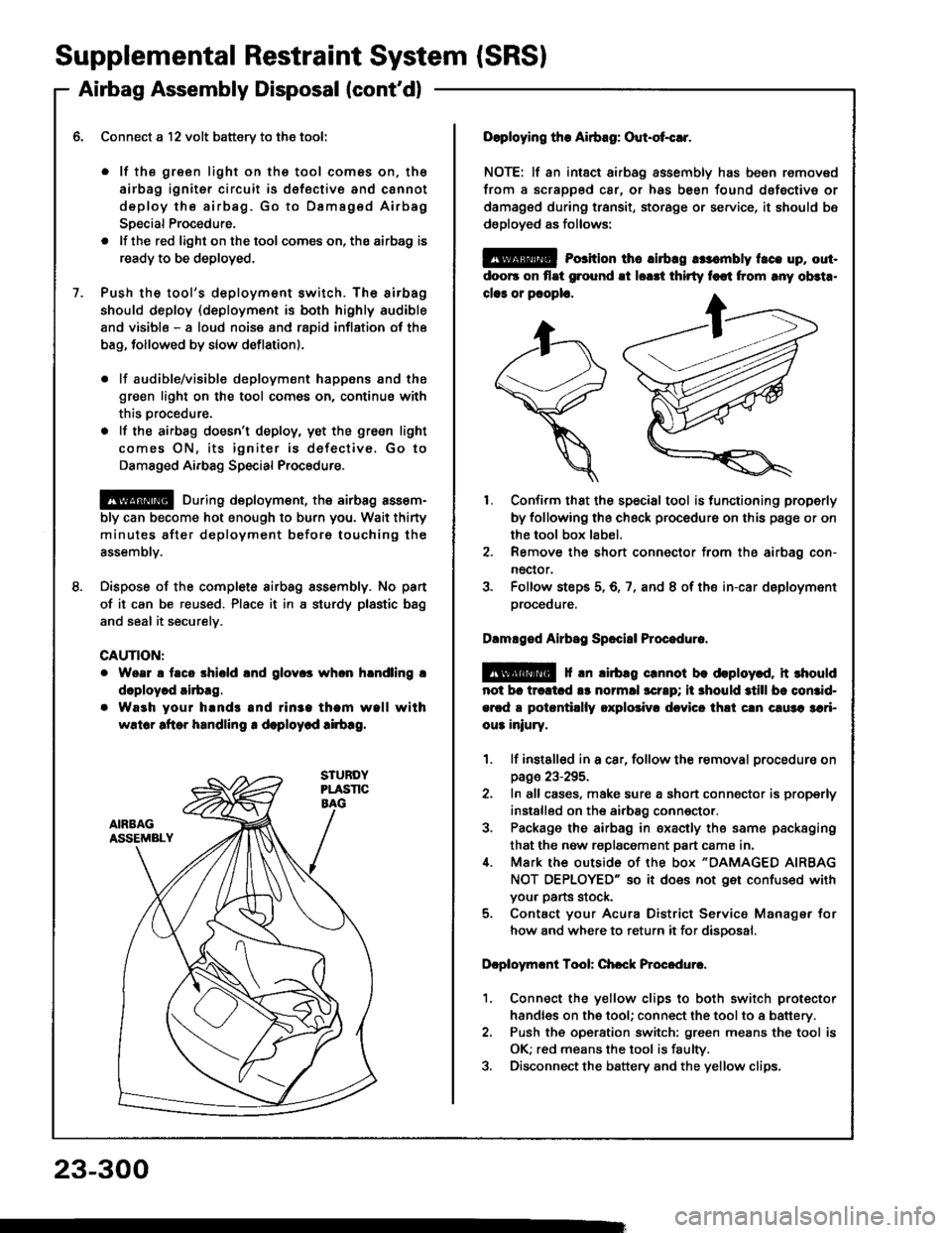
and seal it securelv.
CAUTION:
Woar a taco shiold lnd glov.s whon hlndling !
doploy.d airbag.
Waeh your hands and rin3a tham wall with
wslor aftor handling r deploycd !irb!g.
23-300
Doploying the Airbag: Out-ot{!r.
NOTE: lf an intsct airbag assembly has been removed
from a scrapped car, or has been found dofective or
damagsd during transit, storage or service, it should bs
dsployed as follows:
@ Porition th6 lirbrg rr:.mbly t.ce up, out-
doo6 on flat ground !t lorrt thirty foot from rny ob3t..
clar or pcoplo.
1. Confirm that the special tool is functioning properly
by following the check procedure on this page or on
the tool box label.
2. Remove the short connector from the airbag con-
nector.
3. Folfow steps 5,6,7, and 8 of the in-car deployment
orocequre.
Dlmlged Airbsg Sp.ci8l Procoduro.
E!@ f rn lirbag crnnot be deploy.d, it rhould
not br trcltcd !s normll scrrp; ii 3hould still bc comid-
ercd a potantillly oxplolivr dcvicc thli cln c!u3a 3ari-
ou3 iniury.
1. lf instslled in a car, follow the removal procedure on
page 23-295.
2. In all cases, make sure a short connector is properly
installed on the airbag conn€ctor.
3. Package the airbag in sxacily the same packaging
that the now replacement part cama in.i[. Mark the outside 0f the box "DAMAGED AIRBAG
NOT OEPLOYED" so it does not get confused with
your parts stock.
5. Contact your Acura District Service Manager for
how and where to return it for disoosal.
Dcploymont Tool: Chcck Procedure.
1. Connect the yellow clips to both switch protector
handles on the tool; connect the tool to a battery.
2. Push th€ operation switch: green means the tool is
OK; red means the tool is faulty.
3. Disconnect the battery and the yellow clips.