Remove trans HONDA INTEGRA 1994 4.G User Guide
[x] Cancel search | Manufacturer: HONDA, Model Year: 1994, Model line: INTEGRA, Model: HONDA INTEGRA 1994 4.GPages: 1413, PDF Size: 37.94 MB
Page 352 of 1413
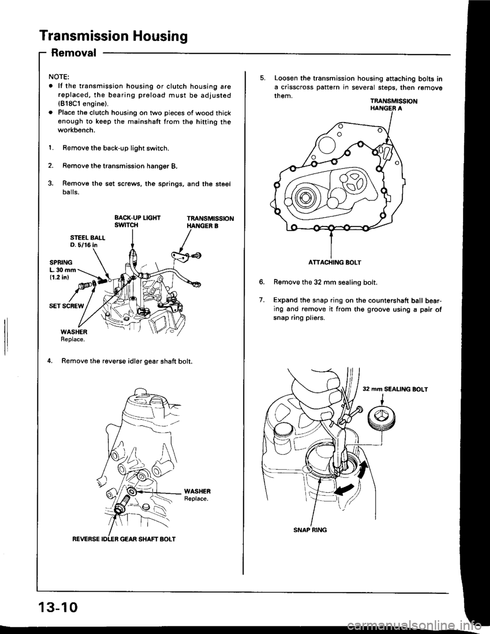
Transmission Housing
Removal
NOTE:
. lf the transmission housing or clutch housing a.ereplaced, the bearing proload must be adjusted(818C1 engine).
. Place the clutch housing on two pieces of wood thickenough to keep the mainshaft from the hitting the
workbench.
1. Remove the back-up light switch.
2. Remove the transmission hanger B,
3. Remove the set screws, the springs, and the steel
balls.
Tna sMtsstoN
SPBINGL. 30 mm11.2 inl
SET SCBEW
WASHERReplace.
4. Remov€ the reverse idler gear shaft bolt,
WASHERReplace.
REVERSE
L
13-10
ATTACHING BOLT
5. Loosen the transmission housing attaching bolts in
a crisscross pattern in several steps. then remove
them.TRANSMISSION
Remove the 32 mm sealing bolt.
Expand the snap ring on ths countershaft ball bear-
ing and remove it from the groove using a pair of
snap ring pliers.
32 mm SEALING BOLT
7.
SNAP RING
Page 353 of 1413
Reverse Change Holder,
Reverse ldler Gear
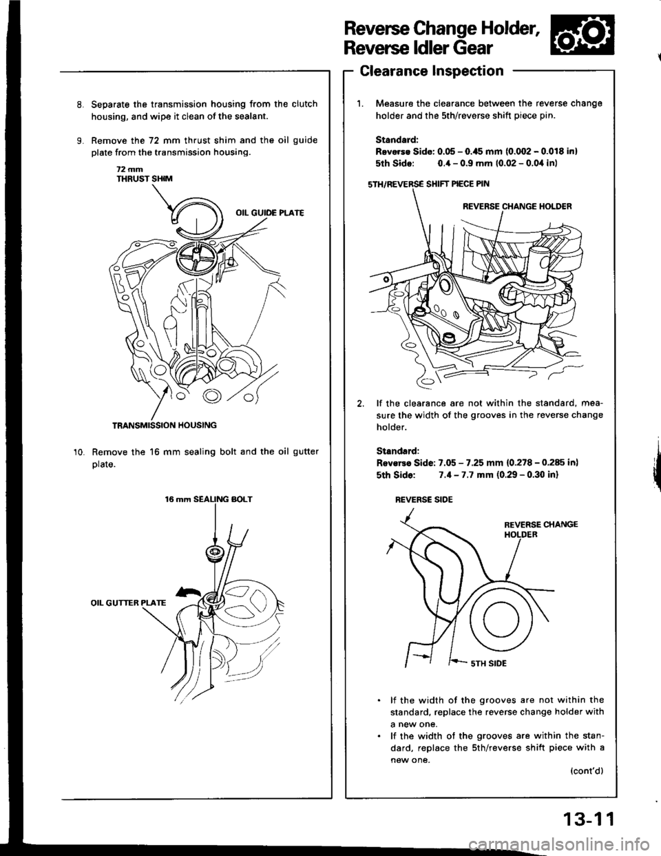
Clearance Inspection
Measure the clearance between the re
holder and the sth/revsrse shift piece p
Standard:
Bevorse Sido: 0.05 - O.ils mm (0.002 - (
5th Sido: o.ia - 0.9 mm 10.02 - 0.0,1
SHIFT PIECE PIN
REVERSE CHANGE
€,
lf the clearance are not within the sti
sure the width of the grooves in the re
holder.
Standsrd:
Rovsrea Side: 7.05 - 7.25 mm {0.278 - (
sth Sido: 7.1-7.7 mm (0.29 - 0.30
REVERSC SIOE
REVERSE
I ' '-- sTH SIDE
lf the width of the grooves are n
standard, replace the reverse chan€
a new one.
lf the width of the grooves are wi
dard, replace the sth/reverse shift
new one,
Separste the transmission housing from the clutch
housing, and wipe it clean of the sealant.
Remove the 72 mm thrust shim and the oil guide
plate from the transmission housing.
t2 mmTHRUST SHIM
TRANSMISSION HOUSING
Remove the 16 mm sealing bolt and the oil gutter
plate.
OIL GUTTER PLATE
10.
reverse cnange
ptn.
.0.018 inl
),1in)
standard, mea-
reverse change
0.285 in)
I inl
not within the
Inge holder with
within the stan-
rift piece with a
(cont'd)
13-1 1
Page 380 of 1413
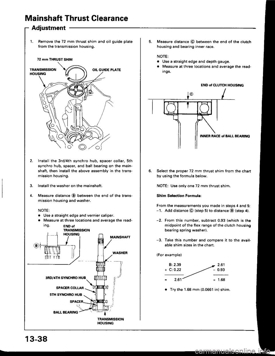
Mainshaft Thrust Glearance
1. Remove the 72 mm thrust shim and oil guide plate
from the transmission housing.
72 mm THRUST SHIM
TRANSMISSIONHOUSINGOIL GUIDE PLATE
Adjustment
\.u
o
Bo
lnstall the 3rd/4th synchro hub, spacer collar, sth
synchro hub, spacer, and ball bearing on the main-
shaft. then install the above assembly in the trans-
mission housing.
Installthe washer on the mainshaft.
Measure distance @ between the end of the trans-
mission housing and washer.
NOTE:
. Use a straight edge and vernief caliper.
. Measure at three locations and averaoe the read-
Ing.END olTRANSMISSIONHOUSINGMAINSHAFT
WASHER
fr
13-38
AALL AEARING
. Try the 1.68 mm (0.0661 in) shim.
5. Measure distance @ betlveen the end of the clutch
housing and bearing inner race.
NOTE:
. Use a straight edge and depth gauge.
a Measure at three locations and average the read-
Ings.
Select the prcpet 72 mm thrust shim from the chart
by using the formula below.
NOTE: Use only one 72 mm thrust shim.
Shim Sslsction Formula:
From the measurements you made in steps 4 and 5:-1. Add distance @ (step 5lto distance @ (step 4).
-2. From this number. subtract 0.93 (which is the
midpoint of the flex range of the clutch housing
bearing spring washerl.
-3. Take this number and compare it to the avaif
able shim sizes in the chart.
(For example)
B:2.39
+ C: O.22
2.61- 0.93
1.68
END of CLUTCH HOUSING
INNEB RACE ot BALL BEARltac
Page 385 of 1413
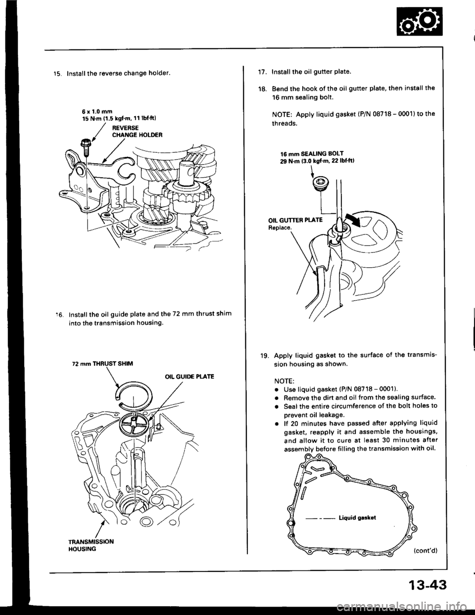
15. Installthe reverse change holder.
6x1.0mm
Installthe oil guide plate and the 72 mm thrust shim
into the transmission housing.
15 N.m (1.5 kgt'm,11 lbfftl
72 mm THRUST SHIM
'18.
Installthe oil gutter plate.
Bend the hook of the oil gutter plate, then install the
16 mm sealing bolt.
NOTE: Apply liquid gasket {P/N 08718 - 0001) to the
threads,
16 mm SEAI-ING BOLT
29 N.m t3.0 kgf m, 22 lbl'ftt
Apply liquid gasket to the surface ot the transmis-
sion housing as shown.
NOTE:
Use liquid gasket (P/N 08718 - 0001)
Remove the dirt and oil from the sealing surface'
Seal the entire circumference of the bolt holes to
prevent oil leakage.
lf 20 minutes have passed after applying liquid
gasket, reapply it and assemble the housings,
and allow it to cure at least 30 minutes after
assembly before filling the transmission with oil.
(cont'd)
19.
a
a
Liquid g.!k.t
13-43
Page 476 of 1413
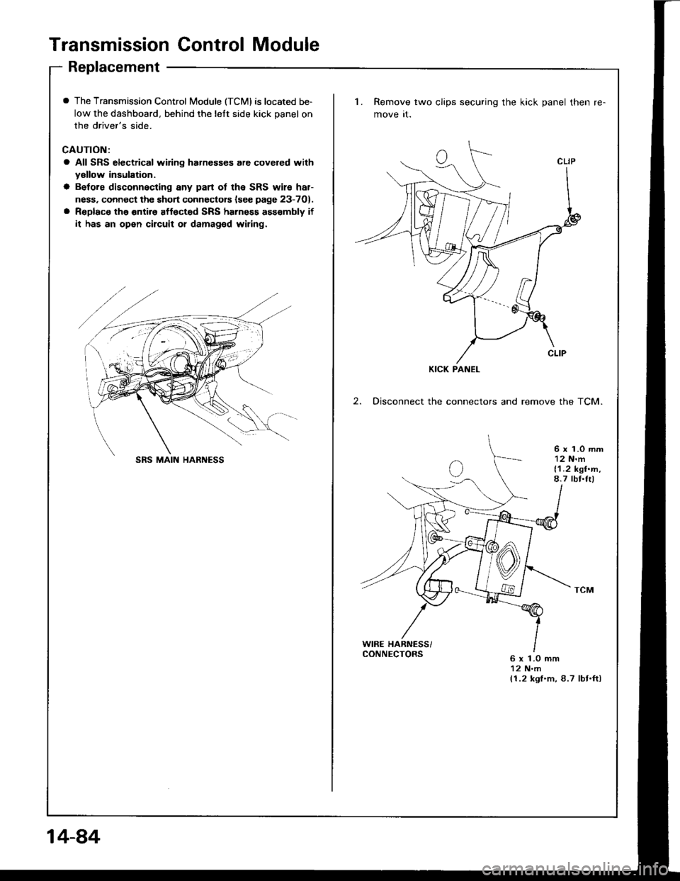
Transmission Control Module
Replacement
I The Transmission Control Module (TCMI is located be-
low the dashboard, behind the lelt side kick panel on
the driver's side.
CAUTION:
a All SRS electrical wiring hahesses are covered withyellow insulation.
a Betore disconnecting any pan ot the SRS wile har-
ness. connect the short connectors lsee page 23-7O).
a Replace the entir6 affected SRS harness ass€mbly if
it has an open circuit or damaged wiring.
1. Remove two clips securing the kick panel then
move it.
2. Disconnect the connectors and remove the TCM.
6 x 1.0 mm12 N'm{1.2 kgf.m,8.7 tbf.Itl
WIRE HARNESS/CONNECTORS6 x 1.0 mm12 N.m(1.2 kgf.m, 8.7 lbt.ftl
KICK PANEL
SRS MAIN HARNESS
14-84
Page 477 of 1413
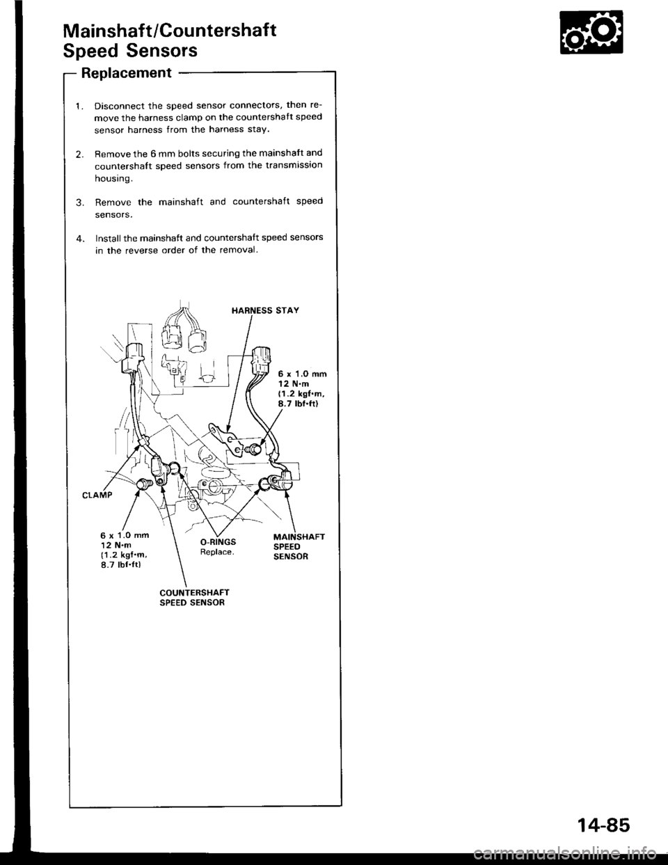
Mainshaft/Countershaft
Speed Sensors
Replacement
Disconnect the speed sensor connectors, then re-
move the harness clamp on the countershatt speed
sensor harness from the harness stay.
Remove the 6 mm bolts securing the mainshaft and
countershalt speed sensors from the transmission
housrng.
Remove the mainshaft and countershaft speed
sensors,
Installthe mainshatt and countershalt speed sensors
in the reverse order of the removal.
COUNTERSHAFTSPEED SENSOR
I{ARNESS STAY
6 x'l,O mml2 N.m{1.2 kgf.m,8.7 tbf.fr)
6 x 1.O mm12 N.m(1.2 kgf.m,8.7 tbf.ltl
14-85
Page 484 of 1413
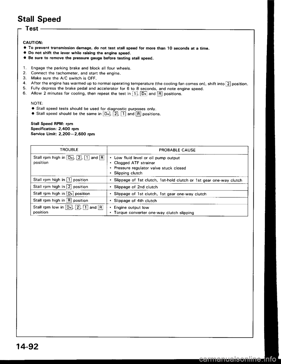
Stall Speed
CAUTION:
a To plevent transmission damage, do not test stall speed fot mote than 1O seconds at a time.a Do not shift the level while raising th€ engine speed.a Be sure to remove the pressure gauge belot€ testing stall speed.
1. Engage the parking brake and block all four wheels.
2. Connect the tachometer, and start the engine.
3. Make sure the A/C switch is OFF.
4. After the engine has warmed up to normal operating temperature (the cooling lan comes on), shift into ft position.
5. Fully depress the brake pedal and accelerator for 6 to 8 seconds. and note engine speed.6. Allow 2 minutes for cooling, then repeat the test in [, fDil and @ positions.
NOTE:
a Stall speed tests should be used lor diagnostic purposes only.. Stall speed should be the same in E, tr. tr and @ positions.
Stall Speed RPM: rpm
Specification: 2,400 rymService Limit: 2,2OO-2,600 tpm
TROUBLEPROBABLE CAUSE
Stall rpm hish in E, E, I and @posrtronLow fluid level or oil pump output
Cloqged ATF strainer
Pressure regulator valve stuck closed
Slipping clutch
Stall rpm high in I positionSlippage of 1st clutch, 1st-hold clutch or 1st gear one-way clutch
Stall rpm high in @ positionSlippage of 2nd clutch
Stall rpm high in @ positionSlippage of 1st clutch, lst gear one-way clutch
Stall rpm high in @ positionSlippage of 4th clutch
Stall rpm low in E, E, I ana @positionEngine output low
Torque converter one-way clutch slipping
14-92
Page 485 of 1413
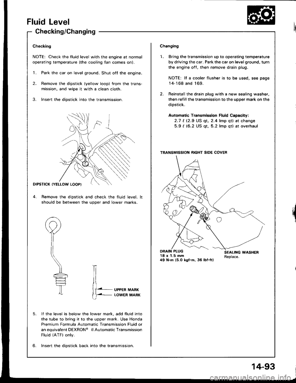
Fluid Level
Checking/Changing
Checking
NOTE: Check the fluid level with the engine at normal
operating temperature (the cooling lan comes on).
1. Park the car on level ground. Shut otf the engine.
2. Remove the dipstick (yellow loop) from the trans-
mission, and wipe it with a clean cloth.
3. Insert the dipstick into the transmission.
DIPSTICK (YELLOW LOOPI
4. Remove the dipstick and check the fluid level.
should be between the uoDer and lower marks.
P
il
\---
T
lf the level is below the lower mark, add fluid into
the tube to bring it to the upper mark. Use Honda
Premium Formula Automatic Transmission Fluid or
anequivalentDEXRON@ llAutomaticTransmission
Fluid (ATF) only.
lnse.t the diDstick back into the transmission.
IT
{J. UPPER MARK
t)-i- LowER MARK
5.
6.
Changing
1. Bring the transmission up to operating temperature
by driving the car. Park the car on level ground, turn
the engine oft, then remove drain plug.
NOTE: lf a cooler flusher is to be used, see page
14-168 and 169.
2. Reinstail the drain plug with a new sealing washer,
then refillthe transmission to the upper mark on the
dipstick.
Automatic Transmission Fluid Capacity:
2.1 | l2.S US qt, 2.4 lmp qt) at change
5.9 ? (6.2 US qt, 5.2 lmp qt) at overhaul
18 x 1.5 mm49 N.m (5.0 kgl.m, 36 lbl.ft)
TRANSMISSION RIGHT SIDE COVER
14-93
Page 491 of 1413
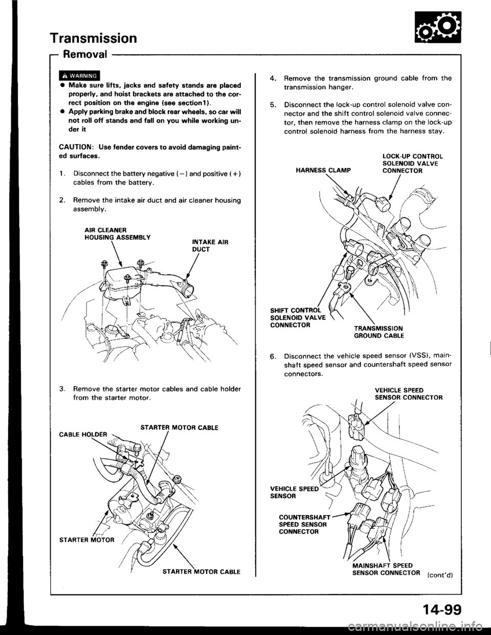
Transmission
Removal
4.Bemove the t.ansmission ground cable from the
transmission hanger.
Disconnect the lock-uD control solenoid valve con-
nector and the shitt control solenoid valve connec-
tor, then remove the harness clamp on the lock-up
control solenoid harness from the harness stav.
a Make sur€ lifts. iacks and safety stands are placad
properly, and hoist brackots are attachod to tho cor-
rect position on ths sngine {seo sectionl }.o Apply parking brake and block rear wheels, so car will
not roll off stands and fall on you whil6 working un-
del it
CAUTION: Use tender covers to avoid damsging paint-
ed surlaces,
1 . Disconnect the battery negative { - } and positive ( + )
cables from the battery.
2. Remove the intake air duct and air cleaner housino
assembly.
HARNESS CLAMP
LOCK-UP CONTROLSOLENOID VALVECONNECTOR
AIR CLEAI{ERHOUSING ASSEMBLY
SHIFT CONTROLSOLENOID VALVECONNECTORTRANSMISSIONGROUND CABI-E
Disconnect the vehicle speed sensor (VSS), main-
shaft sDeed sensor and countershaft speed sensor
connectors.
3.Remove the starter motor cables and cable holder
from the starter motor.VEHICLE SPEEDSENSOR CONNECTOR
STARTER MOTOR CABLECABLE HOLDER
VEHICLE SPEEDSENSOR
COUNTERSHAFTSPEED SENSORCONNECTOR
MAINSHAFT SPEEDSENSORCONNECTOR (cont,d)
STARTER MOTOR?/\
STARTER MOTOR CABLE
4-99
Page 492 of 1413
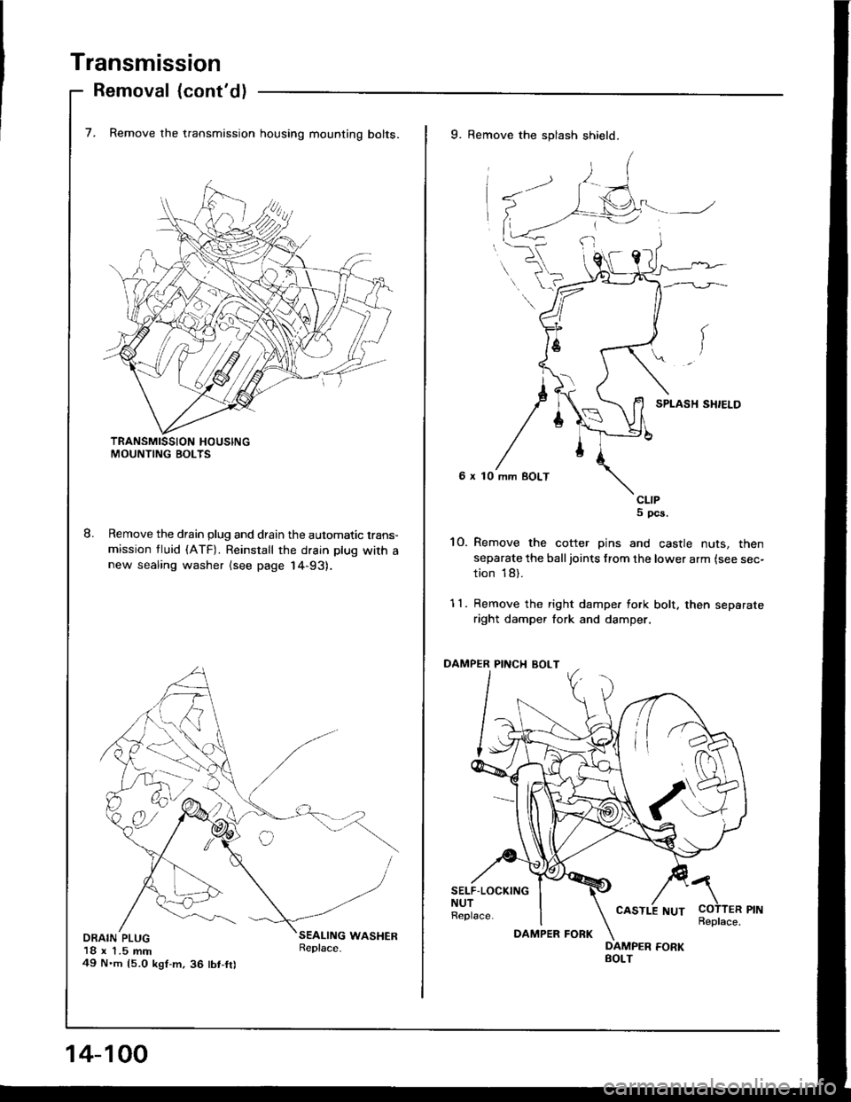
Transmission
Removal {cont'd)
7. Remove the transmission housing mounting bolts.
Remove the drain plug and drain the automatic trans-
mission tluid (ATF). Reinstall the drain plug with anew sealing washer lsee page 14-93).
DRAIN PLUG18 x 1.5 mm49 N'm 15.0 kgt-m,36 tbt-fr)
9. Remove the splash shield.
6 x 10
CLIPS pcs.
10. Remove the cotter pins and castle nuts, then
separate the balljoints from the lower arm {see sec-
tion 18).
11. Remove the right dampe. fork bolt. then separate
right damper fork and damper.
PINCI{ BOLT
SELF.LOCKINGNUTReplace.COTTER PINReplace.
/\
14-100
DAMPER FORK
CASTLE NUT