Remove trans HONDA INTEGRA 1994 4.G Owner's Manual
[x] Cancel search | Manufacturer: HONDA, Model Year: 1994, Model line: INTEGRA, Model: HONDA INTEGRA 1994 4.GPages: 1413, PDF Size: 37.94 MB
Page 494 of 1413
Transmission
Removal (cont'dl
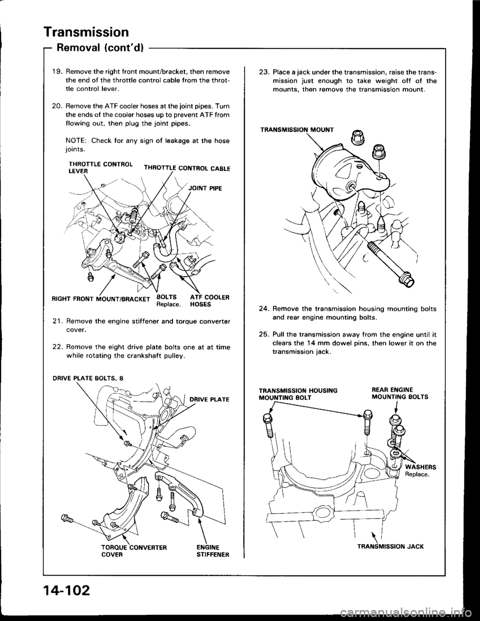
'1 9.Remove the right tront mount/bracket, then remove
the end ol the throttle cont.ol cable trom the throt-
tle control lever.
Remove the ATF cooler hoses at the joint pipes. Turn
the ends of the cooler hoses up to prevent ATF from
flowing out, then plug the joint pipes.
NOTE: Check tor any sign ot leakage at the hosejoints.
THROTTLE CONTROL
23. Place a jack under the transmission, raise the lrans-
mission just enough to take weight off ol the
mounts. then remove the transmission mount.
20.
RrcHT FRoNT iiouNT/BRAcKET BoLTsATF COOLERHOSESReplace.24. Remove the t.ansmission housing mounting bolts
and rear engine mounting bolts.
25. Pull the transmission away from the engine until it
clears the 14 mm dowel Dins, then lower it on the
transmission iack.
21. Remove the engine stiftener and totque converter
cover.
22. Remove the eight drive plate bolts one at at time
while rotating the crankshaft pulley.
WASHERSReplace.
'i z/'l e
" (-J t'
14-102
Page 502 of 1413
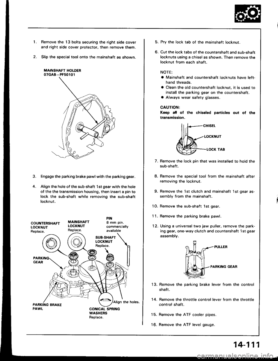
Remove the 13 bolts securing the right side cover
and right side cover protector, then remove them.
Slip the special tool onto the mainshaft as shown.
MAINSHAFT HOLOER07GAB-PF50101
3. Engage the parking brake pawl with the parking gear.
4. Align the hole ot the sub-shaft l st gear with the hole
of the the transmission housing, then insert a pin to
lock the sub-shaft while removing the sub-shaft
locknut.
'1.
COUNTERSHAFTLOCKNUTReplace.
MAINSHAFTLOCKNUTReplace.
8 mm pin.
comm€rciallyavailable
SU8-SHAFTLOCKNUTReplace.
Align the holes.
CONICAL SPNINGWASHERSReplace.
5. Pry the lock tab of the mainshaft locknut.
6. Cut the lock tabs of the countershaft and sub-shaft
locknuts using a chisel as shown. Then remove the
locknut from each shatt.
NOTE;
a Mainshaft and countershaft locknuts have lett-
hand threads.
a Clean the old countershaft locknut, it is used to
install the parking gear on the countershaft.a Always wear safety glasses.
CAUTION:
Keop all of th€ chis€led panicles out of the
tlanamigsion.
llrF-"""*
,fl(,-..- LocKNUr
@-.**'o'
7.
8.
q
10.
11.
12.
13.
14.
15.
to.
Remove the lock pin that was installed to hold the
sub-shaft.
Remove the special tool from the mainshaft after
removing the locknut.
Remove the 1st clutch and mainshaft 1st gear as-
sembly from the mainshaft.
Remove the sub-shaft 1st gear,
Remove the parking brake pawl.
Using a universal two jaw puller. remove the park-
ing gea.. one-way clutch and counlershatt 1st gear
assembly.
PARKING GEAR
Remove the parking brake lever from the control
shaft.
Remove the throttle control lever from the throttle
control shaft.
Remove the ATF cooler pipes.
Remove the ATF level gauge.
14-111
Page 504 of 1413
NOTE:
a Clean all parts thoroughly in solvent o. carburetor
cleaner and d.y with compressed air.a Blow out all passages.
a When removing the transmission housing, replace the
following:. Transmission housing gasket. Lock washer
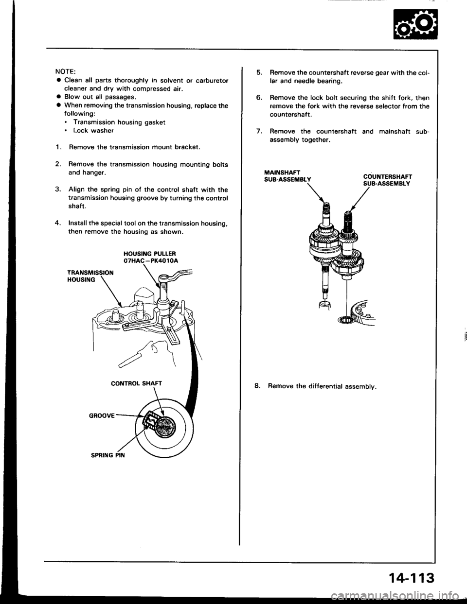
1. Remove the transmission mount b.acket.
Remove the transmission housing mounting bolts
and hanger.
Align the spring pin of the control shaft with the
transmission housing groove by turning the control
shaft.
Install the special tool on the transmission housing,
then remove the housing as shown.
HOUSING PUI-LER07HAC-PK4010A
2.
4.
6.
Remove the countershaft reverse gear with the col-
lar and needle bearing.
Remove the lock bolt securing the shitt fork. then
remove the fork with the reverse selector trom the
countershatt.
Remove the countershaft and mainshaft sub-
assembly together.
8. Remove the ditferential assemblv.
14-113
Page 521 of 1413
Mainshaft
Inspection
a Clearance Measurement
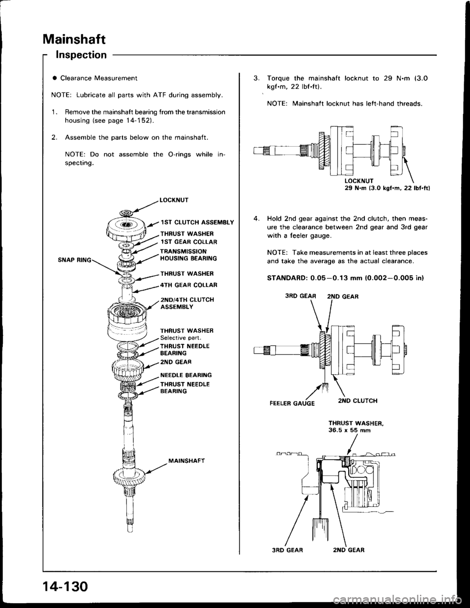
NOTE: Lubricate all parts with ATF during assembly.
1 . Remove the mainshaft bearing lrom the transmission
housing (see page 14-152).
2. Assemble the parts below on the mainshaft.
NOTE: Do not assemble the O-rings while in-
specting.
LOCKNUT
/ 1ST CLUTCH ASSEMBLY
THRUST WASHER
lST GEAR COLLAR
TBANSMISSIONHOUSING BEARING
THRUST WASHER
4TH GEAR COLLAR
2ND/4TH CLUTCHASSEMBLY
THRUST WASHERSelective part.
TI{RUST NEEDLEBEARING
2ND GEAR
NEEDLE BEARING
THRUST NEEOLEBEARING
MAINSI.IAFT
14-130
3RD GEAR2ND GEAR
Torque the mainshaft locknut to 29 N.m (3.0
kgf .m, 22 lbf.ft).
NOTE: Mainshaft locknut has lett-hand threads.
29 N.m (3.0 kgl.m, 22 lbt.ft)
4. Hold 2nd gear against the 2nd clutch. then meas-
ure the clearance between 2nd gear and 3rd gear
with a feeler gauge.
NOTE: Take measurements in at least three Dlaces
and take the average as the actual clea.ance.
STANDARD: 0.05-0.13 mm {0.002-0.005 inl
THRUST WASHER-36.5 x 55 ftm
3RD GEAR 2ND GEAR
Page 525 of 1413
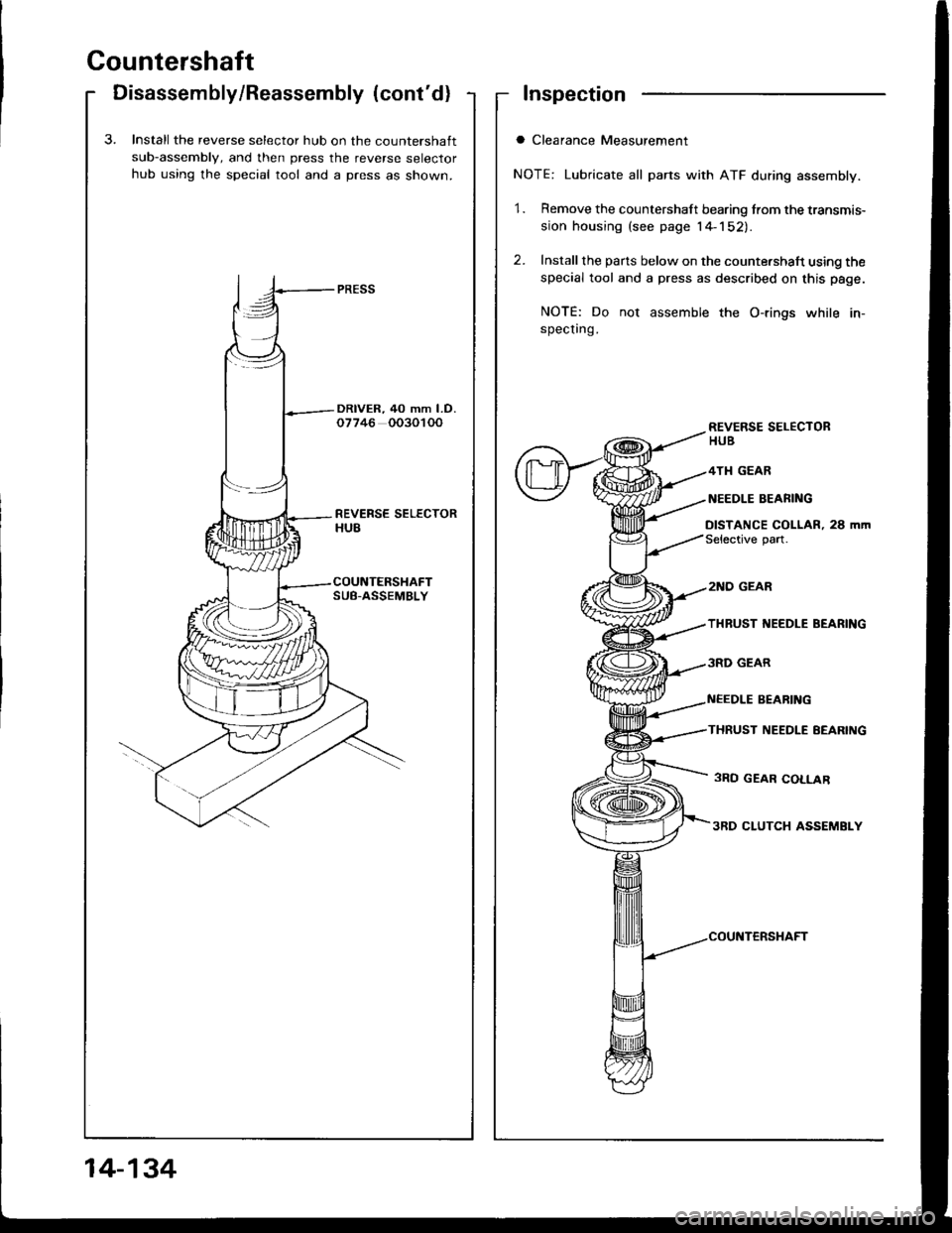
Countershaft
Disassembly/Reassembly (cont'd)Inspection
a Clearance Measurement
NOTE: Lubricate all parts with ATF during assembly.
1. Remove the countershaft bearing from the transmis-
sion housing (see page l4-152).
2. Install the pans below on the counte.shaft using the
special tool and a press as described on this page.
NOTE: Do not assemble the O-rings while in-specting.
aInstall the reverse selector hub on the countershaft
sub-assemblV, and then press the reverse selector
hub using the special tool and a press as shown.
REVERSE SELECTORHUB
4TI{ GEAR
NEEDLE BEAFING
DISTANCE COLLAR, 28 m|nSelective part.
COUNTERSHAFT
14-134
Page 530 of 1413
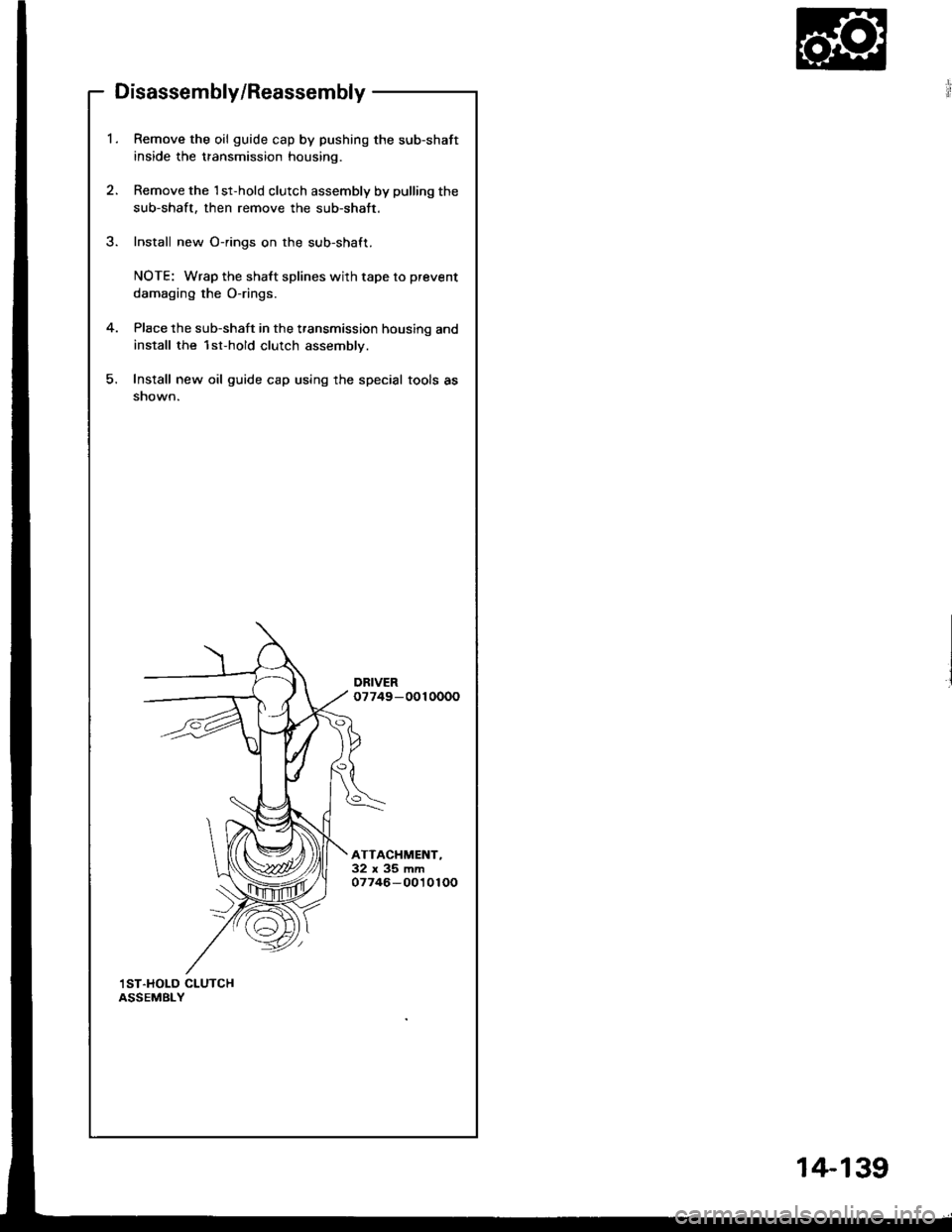
Disassembly/Reassembly
Remove the oil guide cap by pushing the sub-shaft
inside the transmission housing.
Remove the 1st-hold clutch assembly by pulling the
sub-shaft, then remove the sub-shatt.
Install new O-rings on the sub-shaft.
NOTE: Wrap the shaft splines with tape to prevent
damaging the O-rings.
Place the sub-shaft in the transmission housing and
install the 1st-hold clutch assembly.
Install new oil guide cap using the special tools as
snown.
DRIVER07749-0010000
ATTACHMENT-32x35mm07746-0010100
,I ST.HOLD CLUTCHASSEMBLY
14-1 39
Page 531 of 1413
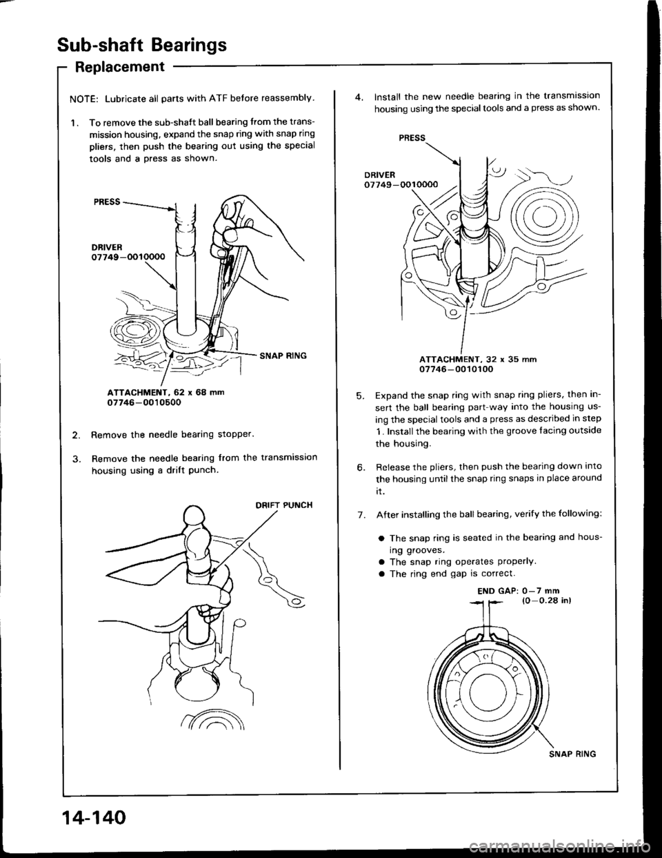
Sub-shaft Bearings
Replacement
NOTE: Lubricate all parts with ATF before reassembly
'l . To remove the sub-shaft ball bearing trom the trans-
mission housing. expand the snap ring with snap ring
pliers, then push the bearing out using the special
tools and a Dress as shown.
ATTACHMENT, 62 x 68 mm07746-0010500
Remove the needle bearing stopper.
Remove the needle bearing from the transmisslon
housing using a drilt Punch.
DRIFT PUNCH
14-140
?A
SNAP RING
PRESS
Install the new needle bearing in the transmlsston
housing using the specialtools and a press as shown.
ATTACHMENT, 32 x 35 mm07746-0010100
Expand the snap ring with snap ring pliers, then in-
sert the ball bearing part way into the housing us-
ing the specialtools and a press as described in step
1. Installthe bearing with the groove facing outside
the housing.
Release the pliers, then push the bearing down into
the housing untilthe snap ring snaps in place around
rt.
After installing the ball bearing, verify the following:
a The snap ring is seated in the bearing and hous-
ing grooves.
a The snap ring ope.ates properly
a The ring end gap is correct.
5.
7.
END GAP: 0-7 mm
Page 543 of 1413
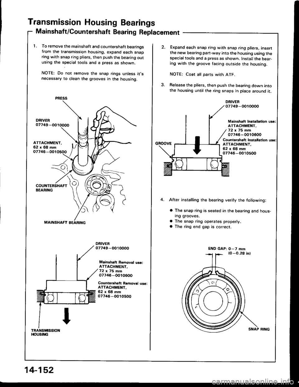
Transmission Housing Bearings
Mainshaft/Countershaft Bearing Replacement
1. To remove the mainshaft and counte.shaft bearingstrom the transmission housing, expand each snapring with snap ring pliers, then push the bearing outusing the special tools and a press as shown,
NOTE: Do not remove the snap rings unless it,snecessafy to clean the grooves in the housing.
ATTACHMENT,62x68mm
Io7746-
---7i
)
MAINSHAFT
Mainshaft Removal uaoiATTACHMENT-72 ,, 75 mmo7746-OOlO600
Counterrhaft Removal uao:ATTACHMENT,62x68mm07746-O010500
TRANSMISSIONt|oustitc
PRESS
14-152
SNAP BING
Expand each snap ring with snap ring pliers, insertthe new bearing pan-way into the housing using thespecialtools and a press as shown. Installthe bear-ing with the groove tacing outside the housing.
NOTE: Coat all parts with ATF.
Release the pliers. then push the bearing down intothe housing until the ring snaps in place around it,
DRIVERo7749-OOIOOOO
GnoovE
Mainshatt Inltallation us6:ATTACHMENT,72x75mm07746-0010600
Counto.shalt In3talldtion uso:ATTACHMENT.62x68mm07746-O010500
4.After installing the bearing verify the lollowing:
a The snap ring is seated in the bearing and hous-In9 grooves.
a The snap ring operates properly
a The ring end gap is correct.
END GAP: O-7 mm
Page 544 of 1413
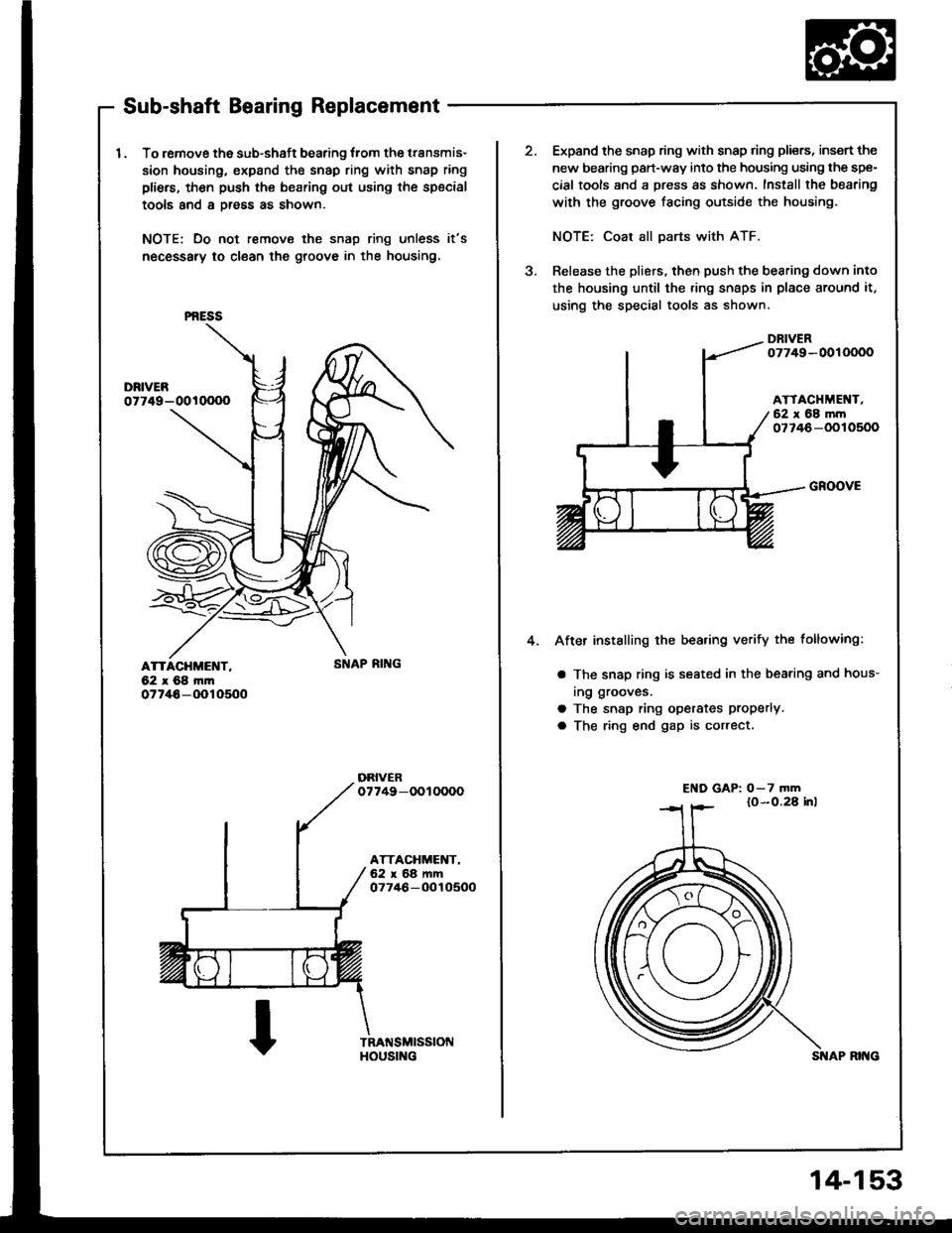
Sub-shaft Bearing Replacement
I . To remove the sub-shaft bearing lrom the transmis-
sion housing, expand the snap ring with snap ring
pliers, then push th€ bearing out using the special
tools and a Dress as shown.
NOTE: Do not remove the snap ring unless it's
necessary to clean the groove in the housing.
ATTACHMENT,62x68m|n07746-(Xr10500
PNESS
HOUS[{G
2.Expand the snap ring with snap ring pliers, insert the
new bearing part-way into the housing using the spe-
cial tools and a press as shown. Install the bearing
with the groove facing outside the housing.
NOTE: Coat all parts with ATF.
Release the pliers, then push the bearing down into
the housing until the ring snaps in place around it,
using the special tools as shown.
DRIVER07749-0010000
ATTACHMEI{T,62 x 68 mrn077/+6-OOlO500
a
4.
GROOVE
After installing the bea.ing verify the following:
a The snap ring is seated in the bearing and hous-
ing grooves.
a The snap ring operates Properlva The ring end gap is correct.
El{D GAP: o-7 mm
14-153
Page 555 of 1413
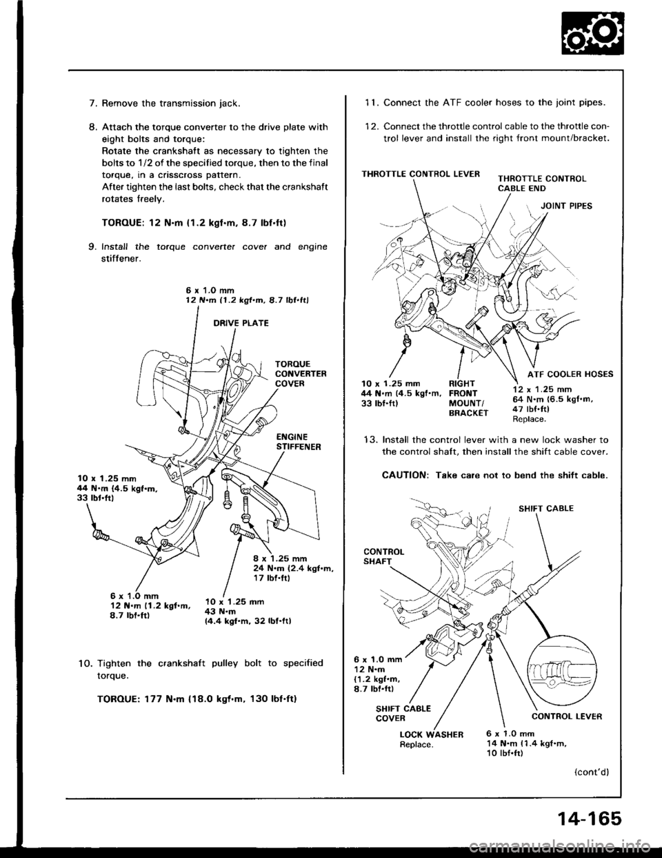
7.Remove the transmission jack.
Attach the torque converter to the drive plate with
eight bolts and torque:
Rotate the crankshatt as necessary to tighten the
bolts to 1/2 of the specilied torque, then to the final
toaque, rn a cnsscross pattern.
After tighten the last bolts, check that the crankshaft
rotates freely.
TOROUE: 12 N.m {1.2 kgl.m.8.7 lbf.ft}
Install the torque converte. cove. and engine
stiffener.
L
9.
6 r 1.O mm12 N.m 11.2 kgt.m, 8.7 lbl.ltl
10.
12 N.m 11.2 kgf.m,8.7 rbt.ft)
Tighten the crankshaft pulley bolt to specified
rorque.
TOROUE: 177 N.m {18.O kgt.m, 130 lbf'ft}
10 x 1.25 mm44 N'm {4.5 kgf.m.33 rbt'frl
8 x '1.25 mm24 N.m (2.4 kgl.m,17 tbf.trl
lO x '1.25 mm43 N.m14.4 kgf.m, 32 lbf.ltl
11. Connect the ATF cooler hoses to the joint pipes.
12. Connect the throttle control cable to the throttle con-
trol lever and install the right front mount/bracket.
THROTTLE CONTROL LEVERTHROTTLE CONTROLCABLE END
JOINT PIPES
12 x 1 .25 mm64 N.m {6.5 kgf.m,47 tbf.ftlReplace.
ATF COOLER HOSES10 x 1.25 mm RIGHT44 N.m (4.5 kgf'm, FRONT33 rbl.ftl MoUNT/BRACK€T
t5.Install the control lever with a new lock washer to
the control shalt. then install the shift cable cover.
CAUTION: Take care not to bend the shift cable.
CONTROLSHAFT
SHIFT CABLE
CONTROL LEVER
6 x 1.0 mm12 N.m{1.2 kgf.m,8.7 lbl.rr)
SHIFT CABLECOVER
LOCK6 x 1.0 mm14 N.m 11.4 kgl.m,10 lbf.fr)
(cont'dl
Replace.ASHER
14-165