brake HONDA INTEGRA 1994 4.G Workshop Manual
[x] Cancel search | Manufacturer: HONDA, Model Year: 1994, Model line: INTEGRA, Model: HONDA INTEGRA 1994 4.GPages: 1413, PDF Size: 37.94 MB
Page 3 of 1413
INTRODUCTION
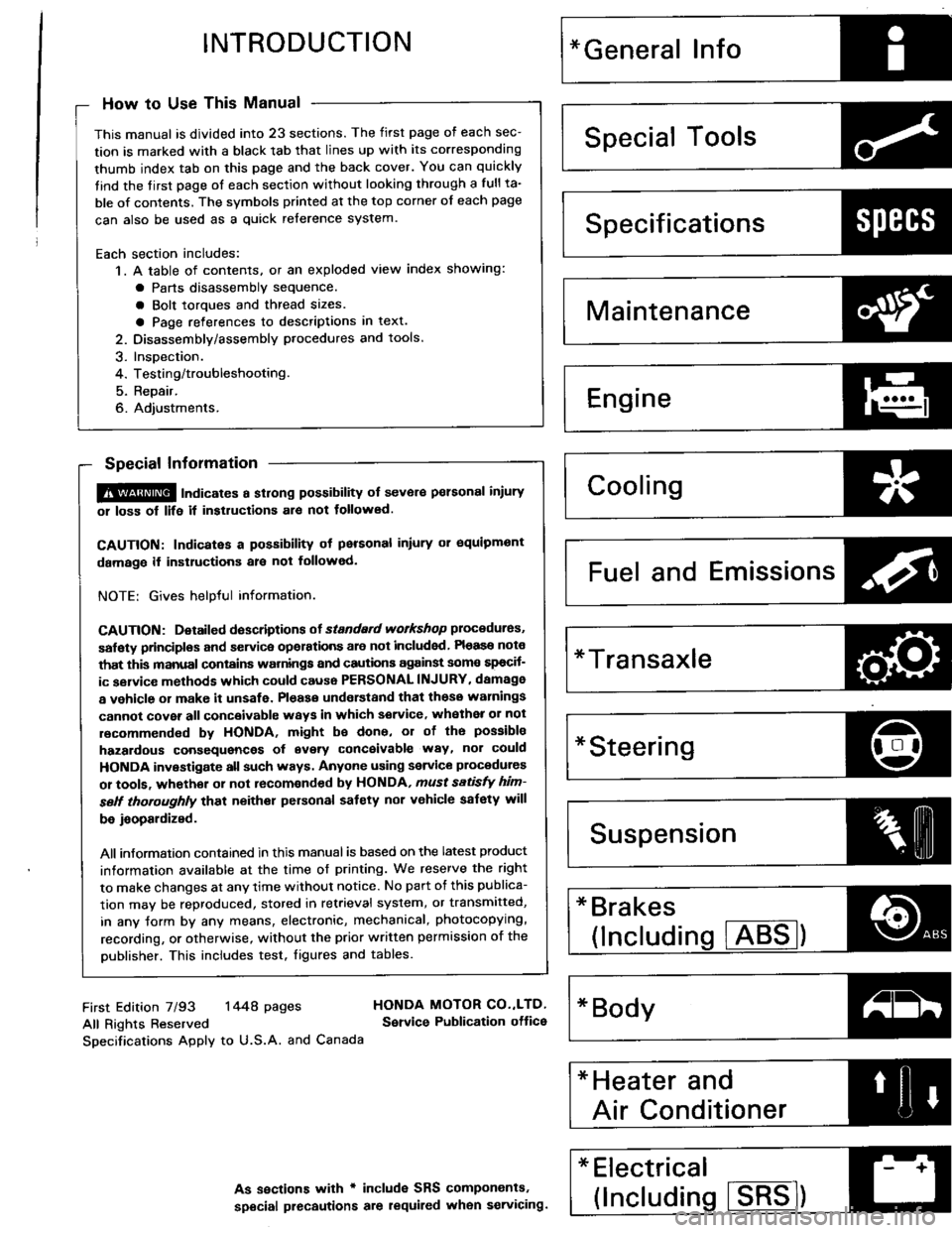
How to Use This Manual
This manual is divided into 23 sections. The first page of each sec-
tion is marked with a black tab that lines up with its corresponding
thumb index tab on this page and the back cover. You can quickly
tind the tirst page of each section without looking through a full ta-
ble of contents. The svmbols printed at the top corner of each page
can also be used as a quick reference system.
Each section includes:
1. A table of contents. or an exploded view index showing:
a Parts disassemblv sequence.
a Bolt toroues and thread sizes.
a Page references to descriptions in text.
2. Disassemblv/assembly procedures and tools.
3. InsDection.
4. Testing/troubleshooting.
5. Repair.
6. Adiustments.
Special Information
@ lnai""tes a strong possibility of sevor€ pelsonal iniury
01 loss of life it instructions al€ not tollowed.
CAUTION: Indicates a possibility ot personal inlury or oquipmont
damage if instructions ale not followed.
NOTE: Gives helpful information.
CAUTfON: Detaifed doscriptions ot standad workshop procedures,
salety principlos and servica opelations are not included Pleaso note
that this manual conlains warnings and cautions against somo spocif-
ic sgrvice methods which could cause PERSONAL INJURY, damage
a vehicle or make it unsafe. Pleaso understand that those warnings
cannot cover all conceivablc waYs in which service, whethea or not
recommended bv HONDA, might be done, or of the possibla
hazardous consequences of svery conceivable way, nor could
HONDA investigate all such ways. Anyone using seryice plocedures
or toofa, whethor 01 not recomonded by HONDA, ,nust sttisfY him-
sett thoroughly that neither personal saf€ty nor v€hicle safety will
be jaopaldized.
All information contained in this manual is based on the latest product
information available at the time of printing. We reserve the right
to make changes at any time without notice. No part of this publica-
tion mav be reproduced, stored in retrieval system, or transmitted,
in any Jorm by any means, electronic, mechanical, photocopying,
recording, or otherwise, without the prior written permission of the
publisher. This includes test. figures and tables.
Specificationstrtl:{lt'
Maintenance4Pi
Engine
H
I-""
Fuel and Emissions Za
*Transaxle
*Steeringr-\
lDl\.t/
* Brakes
(lncludins !TEg)o
*Electrical J--*
(lncludins ISBE)
First Edition 7/93 1448 pages
All Rights Reserved
Specifications Apply to U.S.A. and Canada
HONDA MOTOR CO.,LTD,
Service Publication ottice
As sections with r includ€ SRS components.
special precautions are lequiled when servicing.
Page 14 of 1413
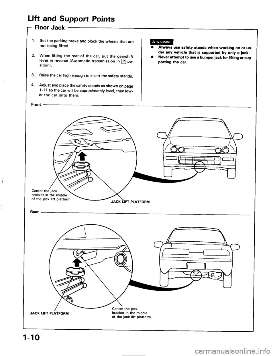
and Support Points
Jack
Set the parking brake and block the wheels that are
not being lifted.
2.When lifting the rearwhen tritrng the rear of the car, put the gearshift
lever in reverse (Automatic transmission in @ po-
of
sition).
Raise the car high enough to insen the safety stands.
Adjust and place the safety stands as shown on page
1-1 1 so the car will be approximately level, then low-
er the car onto them.
Front
oor
ft
FI
Li
4.
1.
a
Always uss satety stands when working oo 01 un-
der any vehicle that is supponed by only a jack.
Naver attompt to use a bumpor iack fo. lifting or sup-
porting tho car,
3.
Center the
bracket in
ot the jack
the middle
lift platform.
jsck
JACK LIFT PLATFORM
Rear
JACK LIFT PLATFORM
Center the jack
bracket in the middle
of the jack Iift platform.
1-10
Page 16 of 1413
Towing
rl
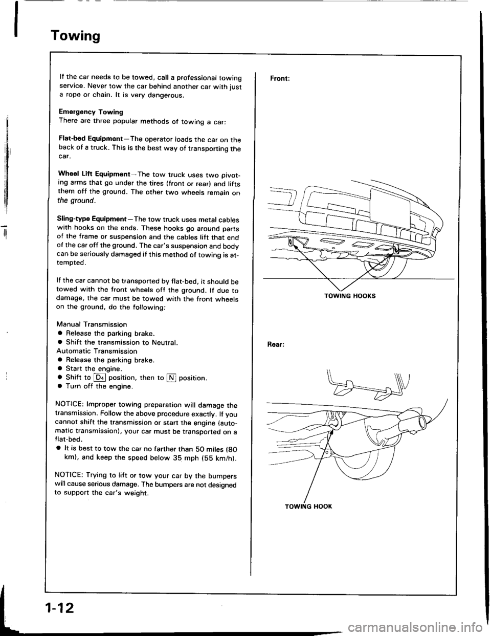
It the car needs to be towed, call a professional towingservice. Never tow the car behind another car with just
a rope or chain. lt is very dange.ous.
Emergency Towing
There are three popular methods of towing a car:
Flat-bed Equipmont-The operator loads the car on theback of a truck. This is the best way of transporting thecar.
Whsol Lift Equipment-The tow truck uses two oivot-ing arms that go under the tires (front or rear) and liftsthem otf the ground. The other two wheels remain onthe ground.
Sling-type Equipmont-The tow truck uses metal cableswith hooks on the ends. These hooks go around partsof the frame or suspension and the cables lift that endof the car off the ground. The car's suspension and bodvcan be seriously damaged if this method of towing is at-tempted.
It the car cannot be transponed by flat-bed, it should betowed with the tfont wheels oft the ground. lf due todamage. the car must be towed with the front wheelson the ground, do the tollowing:
Manual Transmission
a Release the parking brake,a Shift the transmission to Neutral.
Automatic Transmission
a Release the parking brake.a Start the engine.
a Shift to @ oosition, then to S position.
a Turn off the engine.
NOTICE: lmproper towing preparation will damage thetransmission. Follow the above procedure exactly. lf you
cannot shift the transmission or stan the engine (auto-
matic transmission), your car must be transDorted on aflat-bed.
a lt is best to tow the car no tarther than SO miles lgokm). and keep the speed below 3b mph (bE km/h).
NOTICE: Trying to litt or tow your car by the bumperswill cause serious damage. The bumpers are not designedto support the car's weight.
Front:
Real:
TOWING HOOKS
Page 29 of 1413
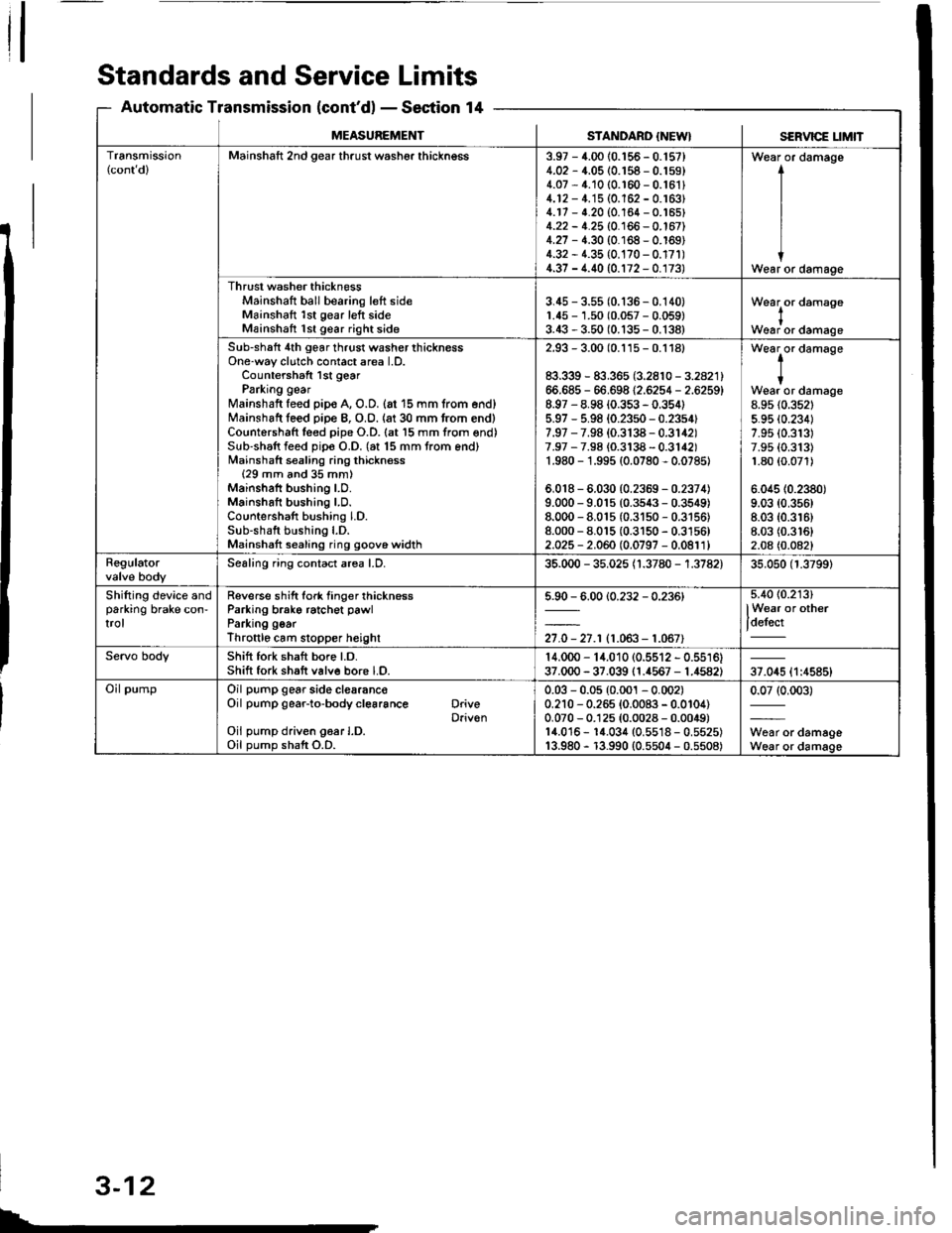
Standards and Service Limits
Automatic Transmission (cont'dl - Section 14
SERVICE t_tMtTMEASUREMENTSTANDARD {NEW}
Transmission(cont dlMainshaft 2nd gear thrust washer thickngss3.97 - 4.00 {0.156 - 0.'t57}4.02 - 4.05 (0.158 - 0.159)4.07 - 4.10 (0.r60 - 0.16114.12 - 4.'15 (0.162 - 0.163)4.17 - 4.20 (0.164 - 0.'�t65)4.22 - 4.25 (0.166 - 0.167)4.27 - 4.30 {0.168 - 0.169)4.32 - 1.35 {0.170 - 0.17r)4.37 - 4.40 (0.172 - 0.173)
Wear or damage
I
I
IWear or damage
Thrust washer thicknessMainshaft ball bearing left sideMainshaft 1st gear left sideMainshatt 1st gear right side
3.45 - 3.55 (0.136 - 0.140)1.45 - 1.50 (0.057 - 0.059)3.43 - 3.50 (0.135 - 0.138)
Wearlor damase
Woar or damage
Sub-shaft 4th gear thrust washer thicknessOne-way clutch contact area l.D.Countershaft lst gearParking gearMainshaft feed pip€ A, O.D. {at 15 mm trom end}Mainshaft leed piDe B, O.O. {at 30 mm from end)Countershaft leed pipe O.D. (at l5 mm from end)Sub-shaft feed pip€ O.D. (at 15 mm trom end)Mainshaft sealing ring thickness{29 mm and 35 mm)Mainshaft bushing LO.Mainshaft bushing LD.Countershaft bushing LD.Sub-shaft bushing l.D.Mainshatt sealing ring goove widlh
2.93 - 3.00 (0.115 - 0.1181
83.339 - 83.365 (3.2810 - 3.2821)66.685 - 66.698 12.6254 - 2.6259)8.97 - 8.98 {0.353 - 0.354)5.97 - 5.98 (0.23s0 - 0.2354f7.97 - 7.98 (0.3138 - 0.3142)7.97 - 7.98 {0.3138 - 0.3142)1.980 - 1.995 (0.0780 - 0.07851
6,018 - 6.030 (0.2359 - 0.2374)9.000 - 9.015 (0.3s43 - 0.3549)8.000 - 8.01s (0.31s0 - 0.3156)8.000 - 8.015 (0.3150 - 0.3156)2.025 - 2.060 (0.0797 - 0.0811)
t-
tWear or damage8.95 {0.352t5.95 (0.2341
7.95 (0.313)
7.9s (0.313)
1.80 {0.071)
6.045 (0.2380)
9.03 (0.356)
8.03 (0.3r6)
8.03 (0.3161
2.08 (0.0821
RegulatorSealing ring contact area LD.35.000 - 35.025 {1.3780 - 1.3782)35.050 (1.3799)
Shifting device andparking brake con-trol
Reverse shift fork tinger thicknessParking brako ratchet pawlParking goarThroftlo cam slopper heighl
5.90 - 6.00 {0.232 - 0.236)
27.0 - 27.r (1.063- 1.067)
5.4O {0.213)
lWear or other
t_'--'
Servo bodyShift fork shaft bore Lo.Shift fork shaft v6lve bore LO.14.000 - 14.010 (0.5512 - 0.5516)37.000 - 37.039 (1.{567 - 1.4582)37.045 {1:4585}
Oil pumpOil pump gear side clearanc€Oil pump gear-to-body cl€6rance DriveDriv€nOil pump driven g6ar I.D.Oil pump shaft O.D.
0.03 - 0.05 (0.001 - 0.002)0.210 - 0.265 {0.0083 - 0.0104)0.070 - 0.125 (0.0028 - 0.0049)14.016 - 1{.034 (0.5518 - 0.5525)13.980 - r3.990 {0.5504 - 0.5508)
0.07 (0.003)
W6ar or damageWear or damage
L
3-12
Page 32 of 1413
![HONDA INTEGRA 1994 4.G Workshop Manual MEASUFEMENTSTANDARD I]{EWI
a gnmentCamber FrontRgarCaster FrontTotaltoe FrontRearFront whe€lturning angle Inward whe€lOutwsrd wh€el
-0. 10 1 1.-0 15 l$igl1. 10�r t"0i2(010.081rN 3:i (0.121ff HONDA INTEGRA 1994 4.G Workshop Manual MEASUFEMENTSTANDARD I]{EWI
a gnmentCamber FrontRgarCaster FrontTotaltoe FrontRearFront whe€lturning angle Inward whe€lOutwsrd wh€el
-0. 10 1 1.-0 15 l$igl1. 10�r t"0i2(010.081rN 3:i (0.121ff](/img/13/6067/w960_6067-31.png)
MEASUFEMENTSTANDARD I]{EWI
a gnmentCamber FrontRgarCaster FrontTotaltoe FrontRearFront whe€lturning angle Inward whe€lOutwsrd wh€el
-0. 10' 1 1.-0' 15' l$igl1. 10'�r t"0i2(010.081rN 3:i (0.121ff)36' 0o' r 2'30. 30'
A1lc€lbearingEnd playFrontRoaa0 - 0.05 (0 - 0.002)0 - 0.05 {0 - 0.002}
Rim runout (Aluminum wheel) AxialRadialRim runout isteelwhgel) AxialRadisl
STANDARD INEWISEBVICE UMIT
0 - 0.7 {0 - 0.03)0 - 0.7 (0 - 0.03)0 - 1.0 {0 - 0.0{)0 - 1.0 (0 - 0.04)
2.0 (0.08)
1.5 (0.06)
2.0 (0.081
r.5 (0.061
SuspensionSestion 18
BrakeSection 19
Air ConditioningScction 22
.1: When using a new bek, adjust dellection or tension to new values. Run the engine tor 5 minules ihen turn it ott.
Readiust detlection or tension to lsed beh values.'2: 81881 engine'3: 818C1 engine
Unit of length: mm {in)
MEASUREMENTSTANDARD {NEWI
trrling brakePlay in strok€ at 200 N {20 kgf, 44 lbt)lever lorceTo b€ lockod when pulled 6 -10
nolchsa
; oot brake,adalPedal heighl lwith floor mat removod)
Free play
M/T160 (6.30)
155 (6.50)
1-5(0.04-0.20)
Vaster cylinderPiston-to-oushrod clearance0 - 0.4 (0 - 0.2)
f,,s4 brakeOisc thickness FrontRe6rDisc runout FrontR6arDisc parallolism Front and rear
Pad lhickness FrontRoar
STANDARD INEWISERVICE LIM]T
20.9 - 21.1 t0.82 - 0.83t8.9 - 9.1 {0.35 - 0.36)
9.5 - 10.5 {0.37 - 0.41}7.0- 8.0 {0.27 - 0.31)
19.0 (0.75)
8.0 (0.31)
0.10 (0.004)
0.r0 (0.00a)
0.015 (0.0006t
r.6 (0.06)
1.6 (0.06)
MEASUREMENTSTANDABO IT{EWI
Ar conditioningLubricant capacity mf (ll oz) Cond€nserEvaporatorLine or hoseReceiverLubricant type: NO-OlL8 {P/N 38899 - PR7 - A0l)
25 (5/6)
40 t1 1/3)10 (lBt
10 (1/31
CompressorLubricant capacity m{ (ll oz}Lubricant tvge: ND-O|L8 (P/N 38899 - PR7 - A01)Stator coil resistance at 68'F (20'C) 0Pulley-to-pressure plate clearance
140';u (4-23';")
3.4- 3.80.5 r 0.15 {0.02 r 0.006)
Compressorb€h'rDetlection with 98 N (10 kgf, 22 lbf)betlveen pulleys
7.5 - 9.5 {0.30 - 0.37)with used b€lt*'�8.5 - 10.5 {0.33 - 0.41}with t/sod belt'35.0 - 7.0 {0.20 - 0.28) with new belt
Belt t€nsion N (kgf, lbl)Measured with belt lension gauge390 - 540 {r0 - 55, 88 - 120} with used beh*'�340 - 490 {35 - 50, 77 - 110} with used belt*3740 - 880 {75 - 90, 170 - 200) with new belt
3-15
Page 36 of 1413
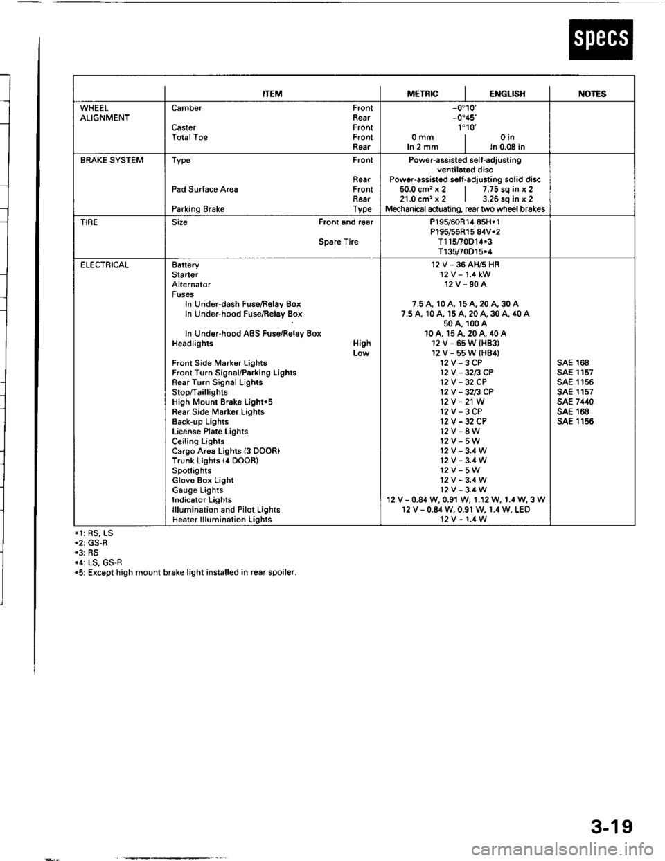
ITEMMETRICIENGLISHIM)TES
WHEELALIGNMENTCamber
CasterTotalToe
FrontRearFrontFrontRear
-0.10'-0.45'�
1'1o'�omm | oinIn 2 mm I ln 0.08 in
BRAKE SYSTEMType Front
RearPad Surface Area FrontRearParking Brake Type
Power-assisted selt-adiustingventilated discPoweFassisted self-adjusting solid discio.u cm. x z | /,/5 so tn x z21.0 cm, x2 | 3.26 sq in x 2Mechanical actuating, rear two wheel brakes
TIRESize Front and r€ar
Spare Tire
P195/60R14 858*1P195/55R15 84V*2T115t0D14*3T135/70O15.4
ELECTRICAL8atteryStarterAlternatorFusesIn Under-dash Fuse/Relay BoxIn Under-hood Fuse/Relay Box
In Under-hood ABS Fuso/Rolay BoxHeadlights
Front Side Marker LightsFront Turn SignauParking LightsRear Turn Signal LighlsStop/Ta illig htsHigh Mount Brake Light'5Fear Side Marker LightsBack-up LightsLiconse Plate LightsCeiling LightsCargo Area Lights (3 DOOR)Trunk Lights l4 DOOR)SpotlightsGlove Box LightGauge LightsIndicator Lightslllumination and Pilot LightsHeater lllumination Lights
High
I2V-36AH6HR'12 V -'1.4 kW12V-90A
7.5 A, 10 A, 15 A, 20 A, 30 A7.5 A, 10 A. 15 A, 20 A, 30 A, 40 A50 A, 100 A10A, 15A,20A,40A12V-6sW{HB3}12V-55W(HB4)12V-3CP12V -32n CP12V -32 CP12V -32n CP12V -21W
12V-3CP12V -32 CP12V-8W12V-5W12v-3.4W12V-3.4W12V-5W12V-3.4W12V-3.4Wv - 0.84 w, 0.91 w, 1.12 W, 1.r W, 3 W12 V - 0.84 W. 0.91 W, 1.4 W. LEO12V-1.4W
sAE 168sAE 1157sAE 1 '�t 55sAE 1157sAE 7440sAE 168sA€ 1156
*1: RS, LS*2: GS-R*3: RS*1: LS, GS-R*5: Except high mount brake light installed in rcar spoiler.
3-19
Page 40 of 1413
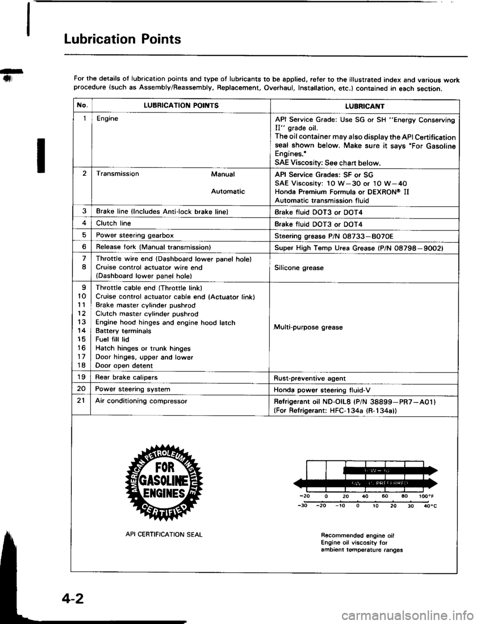
Lubrication Points
For the details ol lubrication points and type of lubricants to be spplied, reter to the illustrated index and various workprocedure (such as Assembly/Reassembly, Replacement, Overhaul, Instatlation, etc.) contained in each section.
No.LUBRICATION POII\ITSLUBRICAI\IT
IEngineAPI Service Grade: Use SG or SH "Energy Conserving
II" grade oil.
The oil container may also display the API Certifications€al shown below. Make sure it says'For GasolineEngines.'
SAE Viscosity; See chan below.
Transmission Manual
Automatic
API Service Grades: SF or SG
SAE Viscosity: 1O W-3O or 1O W-4O
Honda Premium Formula or DEXRON@ II
Automatic transmission fluid
3Brake line (lncludes Anti-lock brake linelBrake fluid DOT3 or DOT4
4Clutch lineBfake tluid DOT3 or DOT4
Power steering gearboxSteoring grease P/N 08733-BO7OE
Release fork (Manual transmission)Supe. High Temp Urea Grease (P/N O8798*9OO2)
8
Throttle wire end {Dashboard lower Danel holel
C.uise cont.ol actuatot wire end
{Dashboard lower Danel holel
Silicone grease
I
10'I '�l
12
13
14
15
to
17
18
Throttle cable end (Throttle linkl
Cruise control actuator cable end lActuator link)
Brake master cvlinder Dushrod
Clutch master cylinder pushrod
Engine hood hinges and engine hood latch
Batte.v terminals
Fuel fill lid
Hatch hinges or trunk hinges
Door hinges. upper and lowet
Door oDen detent
.Multi-purpose grease
19Rear brake calioersRust-p,eventive agant
20Power steering systemHonda power steering tluid-V
21Air conditioning compressorRetrigerant oit ND-otL8 |PlN 38899-pR7-A01)(For Relrigerant: HFC-134a (R-134a))
-20 0 20 r}() 60 ao loooF
-30 -20 -'to o 10 20 30 40"c
Recolnmendod engine oilEngine oil viscosity torambient tgmpelalure rangos
API CERTIFICATION SEAL
Page 50 of 1413
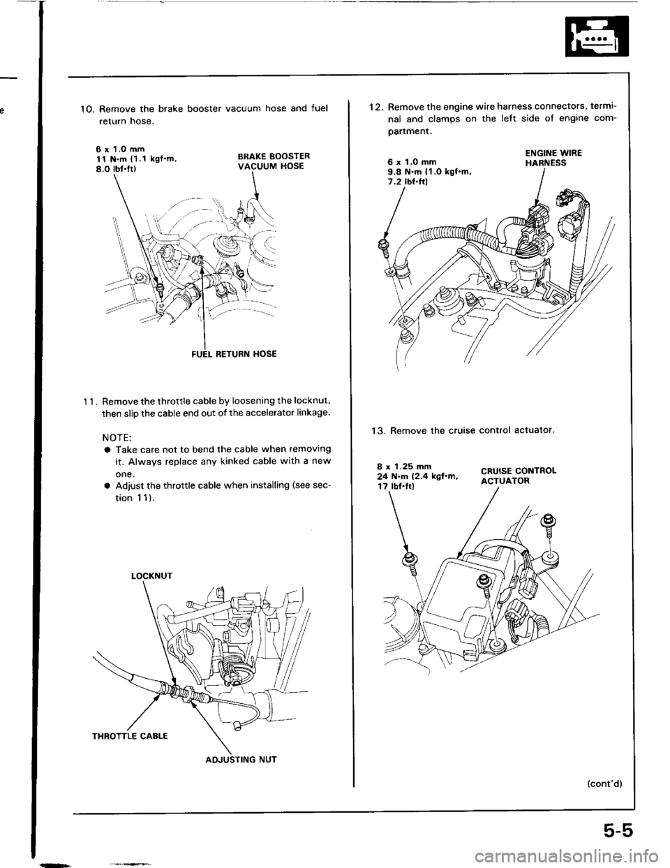
1O. Remove the brake booster vacuum hose and fuel
return hose.
6 x 1.O mm11 N.m {1.1 kgl'm,8.O rbt.ltl
BRAKE BOOSTERVACUUM HOSE
't 1.
BETURN HOSE
Remove the throttle cable by loosening the locknut.
then slip the cable end out of the accelerator linkage.
NOTE:
a Take care not to bend the cable when removing
it. Always replace any kinked cable with a new
one,
a Adjust the throttle cable when installing (see sec-
tion 1 1).
LOCKNUT
AOJUSTING NUT
5-5
't2.Remove the engine wire harness connectors, termi-
nal and clamps on the left side ot engine com-
oartment.
6 x 1.0 mm9.8 N.m {1 .O kgf.m,7.2 tbt.ftl
ENGINE WIREHABNESS
13. Remove the cruise control actualor.
CRUISE CONTROLACTUATOR
8 x 1.25 mm24 N.m (2,4 kgl.m,17 lbf.Irl
Page 79 of 1413
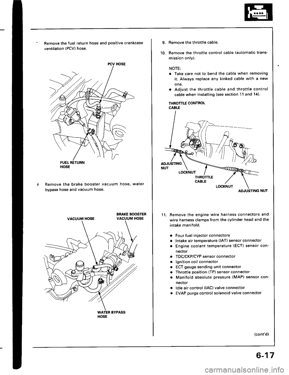
Remove the fuel return hose and positive crankcase
ventilation (PCV) hose.
Remove the brake booster vacuum hose, water
bypass hose and vacuum hose.
ERAKE BOOSTERVACUUM HOSE
HOSE
VACUUM HOSE
HOSE
9.
10.
Remove the throttle cable.
Remove the throttle control cable (automatic trans-
mission only).
NOTE:
. Take care not to bend the cable when removing
it. Always replace any kinked cable with a new
one.
. Adjust the throttle cable and throttle control
cable when installing (see section 11 and 14).
THROTTLE CONTROLCABLE
Remove the engine wire harness connectors and
wire harness clamps trom the cylinder head and the
intake manifold.
Four fuel injector connectors
Intake air temperature (lAT) sensor connector
Engine coolant temperature (ECT) sensor con-
necror
TDC/CKP/CYP sensor connector
lgnition coil connector
ECT gauge sending unit connector
Throttle position (TP) sensor connector
Manifold absolute Dressure (MAP) sensor con-
nector
ldle air control (lAC) valve connector
EVAP purge control solenoid valve connector
11.
a
a
a
a
a
a
a
a
a
(cont'dl
ATI'USTING
6-17
Page 117 of 1413
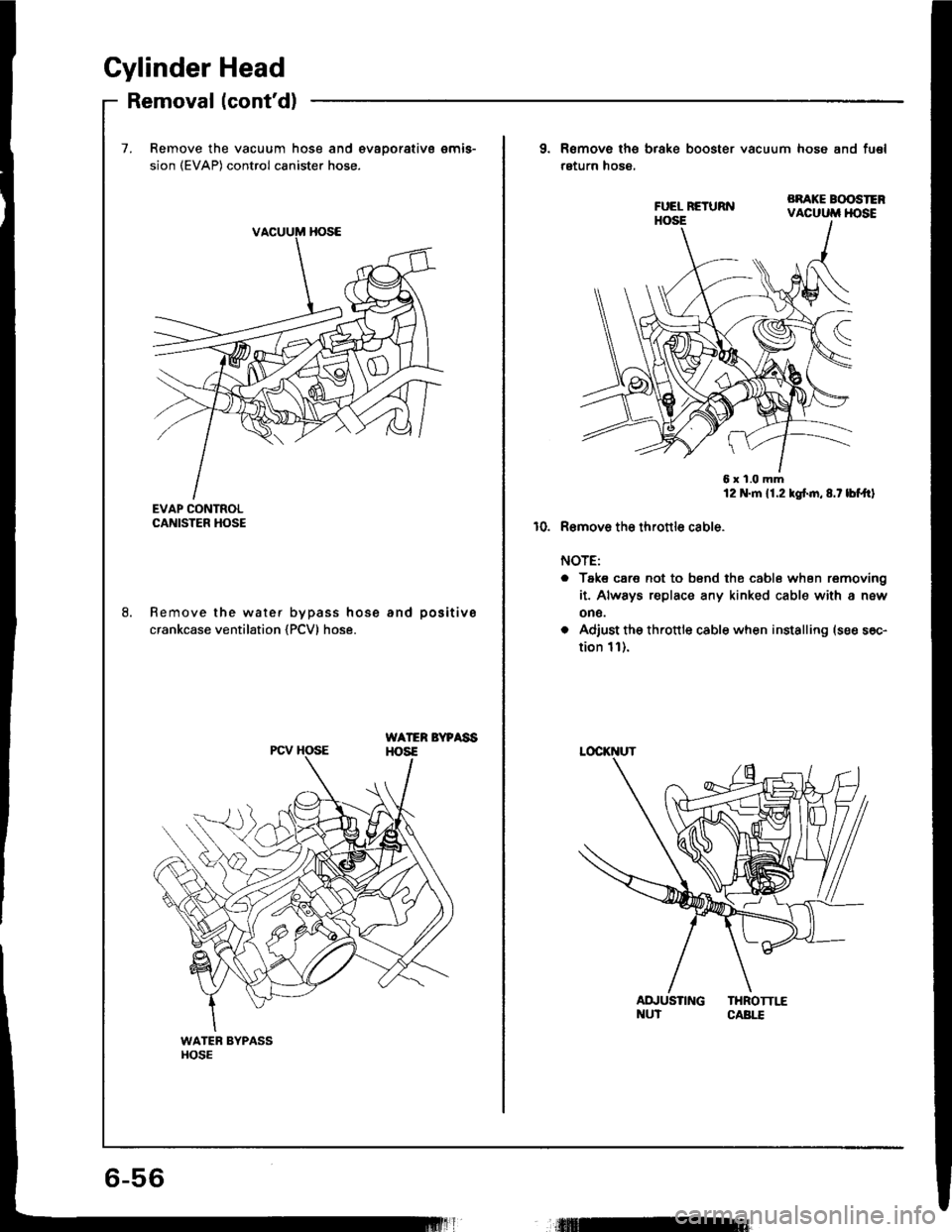
Cylinder Head
Removal (cont'd)
7. Remove the vacuum hose and €vaoorativs emis-
sion (EVAP) control canister hose.
EVAP CONTROLCANISTER HOSE
Remove the water bypass hose and positive
crankcase ventilation {PCV) hose.
WATER BYPAssHOS€PCV HOSE
9. Remove ths brake booster vacuum hose and fu€l
return hose,
BRAKE BOOSTERVACUUM HOSE
6x1.0mm12 N.m 11.2 kgf.n,8.t lbf.trl
10. R€mov6 tho thronlo cable.
NOTE:
o Taks care not to bsnd the cabl6 when removing
it. Always replace any kinked cable with a new
on6.
o Adiust the th.ottle cable when installing (see s6c-
tion 1l).
AD.'USTING THROTTI,"ENUT CABI.T