ECU HONDA INTEGRA 1994 4.G Repair Manual
[x] Cancel search | Manufacturer: HONDA, Model Year: 1994, Model line: INTEGRA, Model: HONDA INTEGRA 1994 4.GPages: 1413, PDF Size: 37.94 MB
Page 1020 of 1413
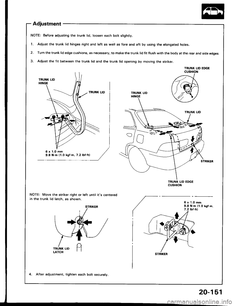
Adjustment
NOTE: Beto.e adjusting the trunk lid, loosen each bolt slightly.
1. Adjust the trunk lid hinges right and left as well as fore and aft by using rhe etongated holes.
2. Turn the trunk lid edge cushions, as necessary, to make the trunk lid fit flush with the body at the rear and side edges.
3. Adjust the lit between the trunk lid and the trunk lid opening by moving the striker.
TRUNK LID EDGECUSHION
NOTE: Move the st.iker right or left until it's centered
in the trunk lid lalch, as shown,6 x '1.0 mrn9.8 N m 11.0 lo,f.m,7.2 tbt.hl
/21
ft(M
Y4Y
TRUNI( LID
TRUNK LIDHINGE
6r1.Omm9.8 N.m 11.0 ksl m, 7.2 lbt'ft|
STRIKER
STRIKER
4. Atter adjuslment, tighten each bolt securelv.
20-151
Page 1023 of 1413
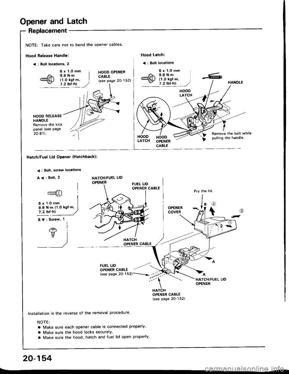
Opener and Latch
Replacement
NOTE: Take care not to bend the opener cables.
Hood Relsase Handle:
< i Bolt locations, 2
Hood Latch:
< : Bolt locations
6 x 1.0 mm9.8Nm(1.0 kgl m,7.2 tbl.lrl
HOOD OPENERCABLE(see page 20'152)
6 x 'l.O mm9.8Nm11.0 kgl m,7 .2 tbt ftl,/HANDLE
HOODLATCH
HOOD RELEASEHANOLERemove the kickpanel (see page
20-91).HOODLATCHHOODOPENERCABLE
Remove the bolt whilepulling the handle.
I
Hatch/Fuel Lid Opener lHatchback):
< : Bolt, sclow locations
A
6' I
vl
/
HATCHiFUEL LID
OPENER
6 x 1.0 mm
9.8 N m 11.0 kgl'm,
7.2 tbl.fr)
FUEL LIDOPENER CAELE
lnstallation is the reverse of the removal procedure'
NOTE:
a Make sure each opener cable is connected properly
a Make sure the hood locks securely
a Make sure the hood, hatch and fuel lid open properly.
the
J'o
t
OPENERCOVER
HATCHOPENER CABLE(see page 20-152)
@
t-
20-154
Page 1024 of 1413
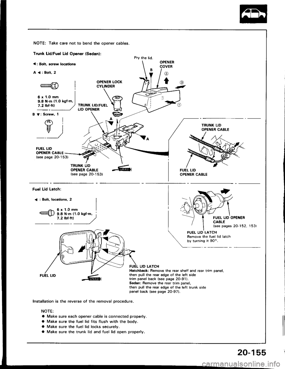
NOTE: Take care not to bend the opener cables.
Trunk Lid/Fuel Lid Oponer {Sodan}:
< : Bolt, scrow locatlon!
A<:Bolr,2
OPENER LOCKCYLINDER
TRUNK LID/FUELLID OPENER
B V: Scrow, 1
AI-}{- IH. I
_:_)
FUEL LID
Pry the ljd.OPENERCOVER
o
to-*rr*@
6 r 1.0 mm
()t
OP€NER CABLE(seo page 2O-153)
TRUNK LIDOPENER CABLE(see page 20-1 53)
9.8 N m 11.O kgl m,
Fuol Lid Lstch:
< : Boh, locotions, 2
6r1.0mm
FUEL LID OP€NERCAALE(see pages 20-152, 153)
9.8 N m 11.0 ksl'm, i7 '2 tbt'''l
------,//
FUEL LID
lnstallation is the reverse of the removal orocedure.
NOTE:
a Make sure each opener cable is connected properly.
a Make sure the fuel lid fits flush with the body.
a Make sure the tuel lid locks securelv.
a Make sure the trunk lid and fuel lid open properly.
LIO LATCHHatchbock: Remove the rear shelf and rear trim oanel.then pull the rear edge ot the lett sidetrim panel back (soe page 2O-91).Sodan: Remove the rear trim panel,then pull the rear edge of the left trunk sidepanel back {see page 2O-971.
FUEL LIO LATCHRemove the fuel lid latchby turning it 90o.
20-155
Page 1025 of 1413
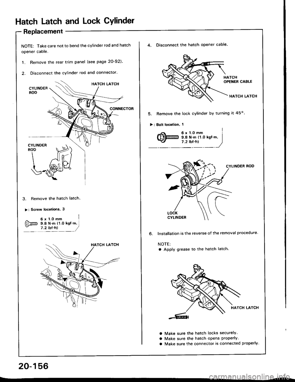
Hatch Latch and Lock CYlindet
Replacement
NOTE: Take care not 10 bend the cylinder rod and hatch
opener cable.
1. Remove the rear trim panel (see page 20-921.
2. Disconnect the cylinder rod and connector.
3. Remove the hatch latch.
>: Screw locatiois, 3
^ 6x1.omm I
{Dm s.e N m (1.0 ksl m,- ,?tb:tn __/
20-156
4. Disconnect the hatch opener cable.
HATCH LATCH
5. Remove the lock cylinder by turning it 45o
>: Bolt localion, 1
o.
CYLINDER ROD
lnstallalion is the reverse of the removal procedure.
NOTE:
a Apply grease to the hatch latch.
HATCH LATCH
Make sure the hatch locks securely.
Make sure the hatch opens properly.
Make sure the connector is connected properly.
a
a
a
Page 1026 of 1413
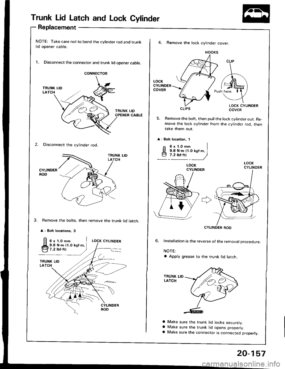
Trunk Lid Latch and Lock Cylinder
Replacement
NOTE: Take care not to bend the cylinder rod and trunklid opener cable.
l. Disconnect the connector and trunk lid opener cable.
CONNECTOR
2. Disconnect the cylinder rod.
CYLINDERROD
Remove the bolts, then remove the trunk lid latch.
A : Bolt locations, 3
LIDCABLE
4. Remove the lock cylinder cover.
HOOKS
LOCK CYLINDERCOVER
5. Remove the bolt, then pull the lock cylinder out. Re,move the lock cylinder trom the cylinder rod, thentake them out.
: Bolt location, 'l
CLIP
CLIPS
F 6xl.Omm I
q;i!!"jy
LOCKCYLINDER
CYLINDER ROD
6. Installation is the reverse ol the removat proceoure.
NOTE:
a Apply grease to the trunk lid latch,
a Make sure the trunk lid locks securelV.a Make sure the trunk lid opens properly.a Make sure the connector is connected properly.
/ ./,.,
,/'e4
20-157
Page 1030 of 1413
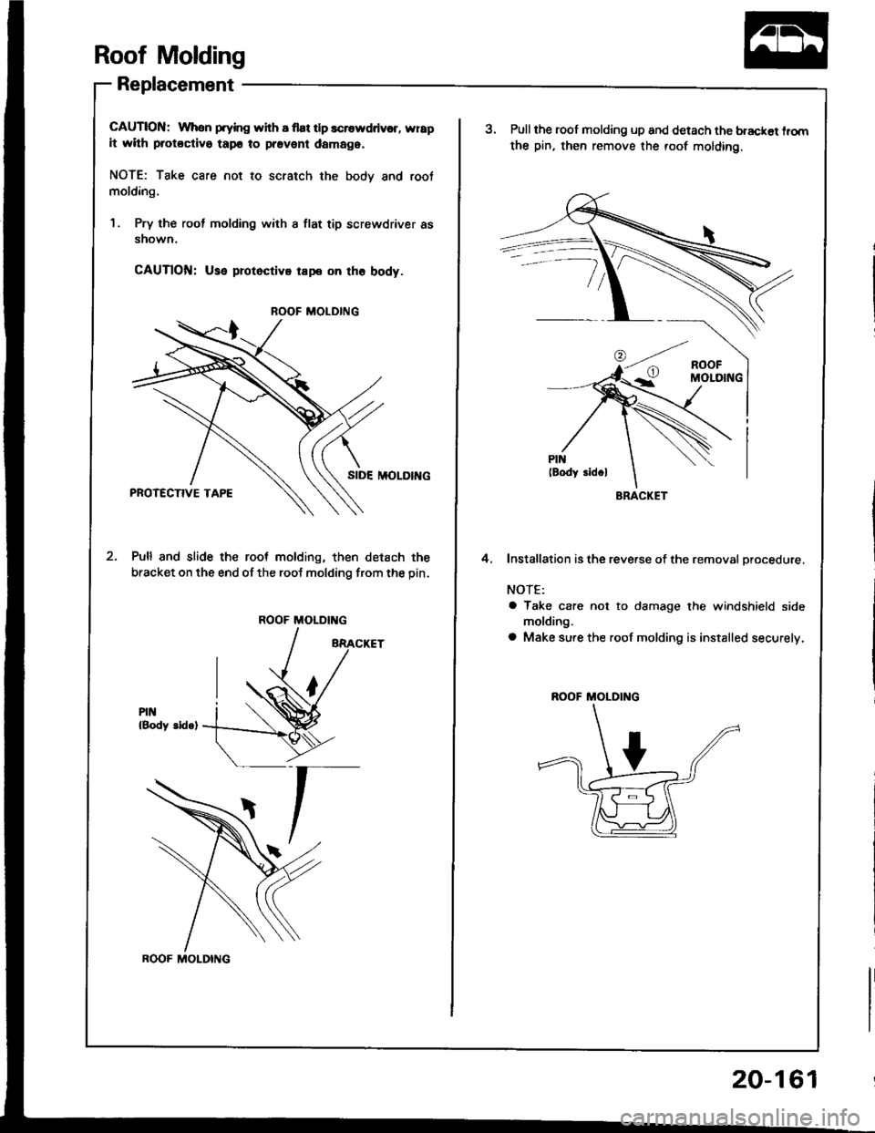
Roof Molding
Replacement
CAUTION: When prying with I flat tlp scrowddv€r, wrap
it with protoctivo tapo to pravent damag6.
NOTE: Take care not to scratch the bodv and root
molding.
1 . Pry the rool molding with a flat tip screwdriver as
snown.
CAUTlOfil: Use protoctivo rape on tho body.
SIDE MOLOII{G
Pull and slide the root molding, then detach the
bracket on the end of the roof molding from the pin.
PIN{Body ddq)
ROOF MOLDING
ROOF MOLDING
ROOF MOLDING
20-161
BRACKET
aPull the roof molding up and detach the bracket lrom
the pin, then remove the roof molding.
Installation is the reverse of the removal orocedure.
NOTE:
a Take care not to damage the windshield side
molding.
a Make sure the roof molding is installed securely.
4.
R(X)F MOLDING
Page 1060 of 1413
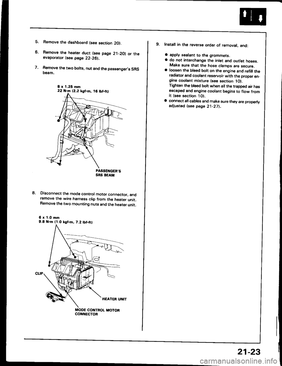
5.
6.
7.
Rsmove the dashboard (see section 2O).
Remove the heater duct (see page 21-20) or theevaporator lse€ page 22-26).
Rsmove the two bolts, nut and the passenger,s SRS(}eam.
PASSEIVGER'SSRS EEAM
Disconnect the mode control motor conngctor, andremove the wire harness clip from the h€8ter unit.Remove the two mounting nuts and the haater unit.
6 r 1.0 mm9.8 .m (l.O kgt.m, 7.2 tbt.frl
MODE COI{TROL I,IOTORcol{t{€cToF
8.
8 x 1,26 mln22 N.m 12.2 kgf.m, 18 tbt.ttl
9. Install in the reverse order of removal, and:
a apply sealant to the grommets.a do not int6rchange the inlet and outl€t hoses.Make sure that the hose clamps are secure.a loosen th€ ble6d bolt on th6 engine and r€fillthetadiator and coolant r€servoir with the propsr en_gine coolant mixture (sse section 1O).Tighten the blsed boh when all the trapped air has6sc8p6d and engine coolant begins to flow fromit (see section 1O).a connect all csbles and make sure they 8re properlyadiusted (see pdge 21-271.
21-23
Page 1100 of 1413
and com
it with a
a
a
a
a
4t l\-N
r-
-l/
Compressor
Clutch Overhaul (cont'dl
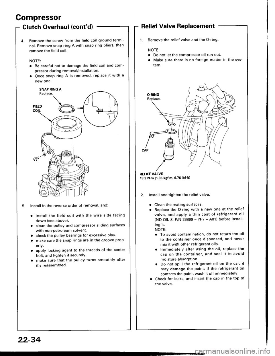
Remove the screw from the field coil ground terma-
nal. Remove snap ring A with snap rjng pliers, then
remove the field coil.
NOTE:
. Be careful not to damage the field coil
pressor during removal/installation.
. Once snap ring A is removed, replace
new one.
SNAP RING AReplace.
FIELDcorL
5. lnstall in the reverse order of removal, and:
install the field coil with the wire side facing
down (see above).
clean the pulley and compressor sliding surfaces
with non-petroleum solvent.
check the pulley bearings for excessive play.
make sure the snap rings are in the groove prop-
efly.
apply locking agent to the threads of the center
bolt, and tighten it securelY
make sure that the pulley turns smoothly after
it's reassembled.
1. Remove the relief valve and the O-ring.
NOTE:
. Do not let the compressor oil run out.
. Make sure there is no foreign matter in the sys-
tem.
RELIEF VALVE13.2 N.m {1.35 kgtm,9.76lbtftl
2. lnstall and tighten the relief valve.
Clean the mating surfaces.
Replace the O-ring with a new one at the relief
valve, and apply a thin coat of refrigerant oal
(ND-OIL 8: P/N 38899 - PR7 - A01) before install-
ing it.
NOTE:
. To avoid contamination, do not return the oil
to the container once dispensed, and never
mix it with other refrigerant oils.
. lmmediately after using the oil, replace the
cap on the container, and seal it to avoid
moisture absorption.
. Do not spill the refrigerant oil on the car; lt
may damage the painu if the refrigerant oil
contacts the paint, wash it off immediately.
Check for leaks, and insert the cap in the top of
the valve.
22-34
Page 1103 of 1413

Condenser
Replacement
RAOIATOR UPPENMOUNT BRACKETS
Recover the relrigerant with a Becovery/Recycling/
Charging System (see page 22-221.
Remove the coolant reservoir,
NOTE: Do not disconnect the reservoir hose from
the coolant reservoir and the radiator.
COOLANT RESERVOIR
Remo.ve the bolts and the radiator upper mount
brackets, and remove the bolt from thg suction hose
bracket.
9.8 N.m {1.0 kgf.m.7.2 lbtftl
'1Iffi
22-37
6x1.0mm9.8 N.m (1.0 kgl.m,7.2 lbt.ft)
......-.....
CONOENSER LINE
Remove the bolts. and disconnect the discharge line
and the condenser line from the condenser.
NOTE: Plug or cap the lines immediately after dis-
connecting to avoid moisture and dust contamina-
tion into the system.
DISCHARGE LINE
Remove the two mounting bolts, then lift out the
condenser as shown.
NOTE: Do not damage the radiator and condenser
fins when removing the condenser.
6x1.0mm9.8 N.m (1.0 kgf.m, 7.2 lbl.tt)
Install in the reverse order of removal. and:
. if you're installing a new condenser, add refriger-
ant oil (ND-OIL 8: P/N 38899 - PR7 - A01) (see
page 22-21t,.
. replace the O-rings with new ones at each fitting,
and apply a thin coat of refrigerant oil {ND-OIL 8:
P/N 38899 - PR7 - A01) before installing them.
NOTE: Be sure to use the right O-rings for HFC-
134a (R-134a) to avoid leakage.
a do not damage the radiator and condenser fins
when installing the condenser,
. be sure to install the condenser mount cushions
securely into the holes.
. charge the system (see page 22-39) and test its
performance (see page 22 24!�.
Page 1110 of 1413
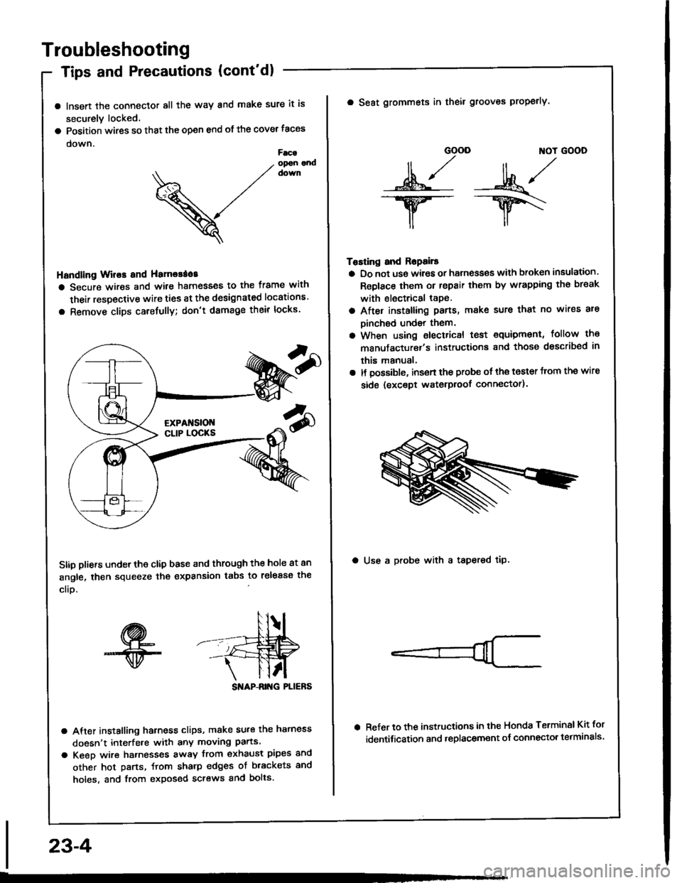
Troubleshooting
Tips and Precautions (cont'dl
a lnsert the connector all the way and make sure it is
securely locked.
a Position wires so that the open end of the cover taces
down.Facaopon andcown
V
Handling Wir€s and Hamorao8
a Secure wires and wile harnesses to the frame with
their respective wire ties at the designated locations'
a Remove clips carefully; don't damage their locks'
Stip pliers under the clip base and through the hole at an
angle, then squeeze the expansion tabs to release the
clio.
SI'IAP-ANG PLIERS
a After installing harness clips, make su.€ the hatness
doesn't interfe.e with any moving parts.
a Keeo wire hatnesses away from exhaust pipes and
other hot parts, ftom sharp edges of brackets and
holes, and from exposed screws and bolts.
23-4
GOOD ]TOT GOOD
n,/r/ll ,,' ll ,,
s*j -:ut*/-.w-- --ry\
il,,
Tosting and Ropails
a Do not us€ wires or harness€s with broken insulation.
Replace them or repair them by wrapping th€ break
with electrical tape.
a After installing pans, make sure that no wir€s are
Dinched undsr them.
a When using electrical test €quipment, follow the
manufacturer's instructiona and those dsscribed in
this manual,
a It possible, insert the probe of the toster from the wire
side {except waterproof connector).
a Seat grommets in theil grooves properly.
a Use a probe with a tapered tip.
Refer to the instructions in the Honda Terminsl Kit for
identification and .eplacement o{ connector telminals'