ECU HONDA INTEGRA 1994 4.G Owner's Manual
[x] Cancel search | Manufacturer: HONDA, Model Year: 1994, Model line: INTEGRA, Model: HONDA INTEGRA 1994 4.GPages: 1413, PDF Size: 37.94 MB
Page 504 of 1413
NOTE:
a Clean all parts thoroughly in solvent o. carburetor
cleaner and d.y with compressed air.a Blow out all passages.
a When removing the transmission housing, replace the
following:. Transmission housing gasket. Lock washer
1. Remove the transmission mount b.acket.
Remove the transmission housing mounting bolts
and hanger.
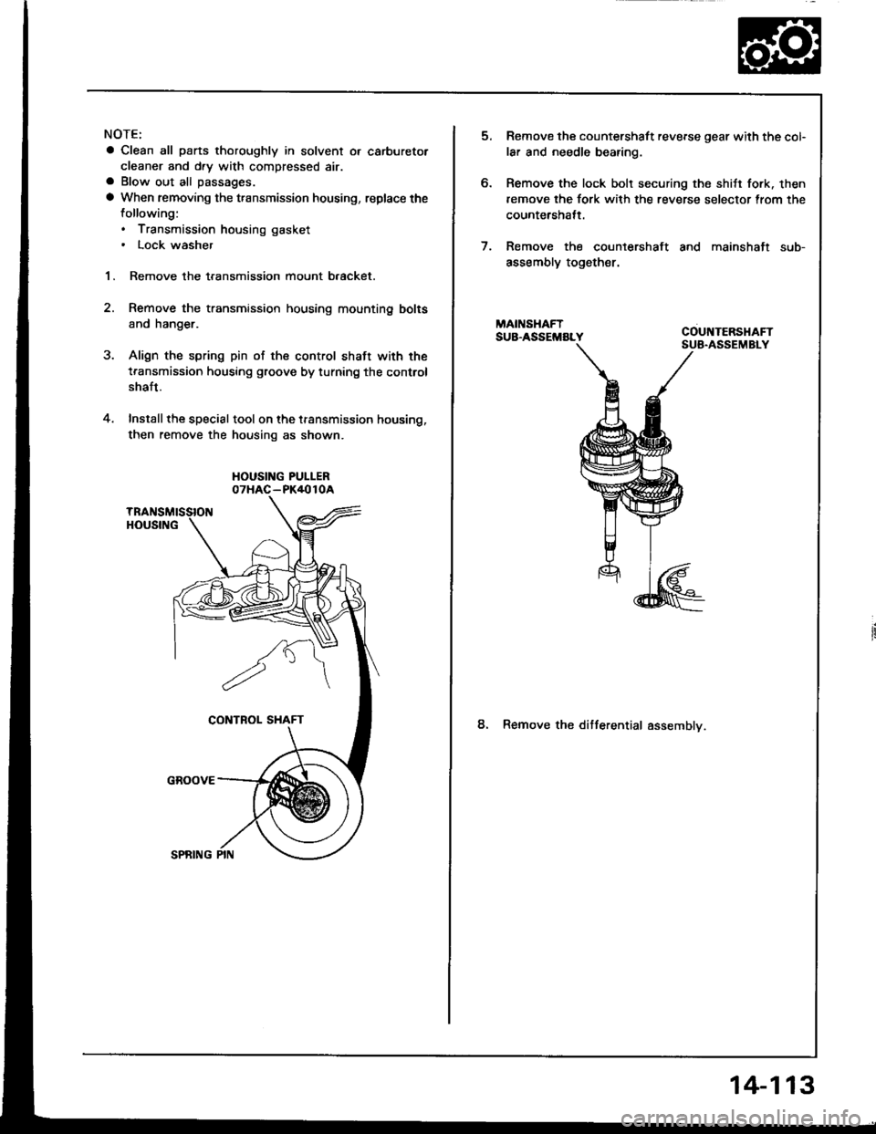
Align the spring pin of the control shaft with the
transmission housing groove by turning the control
shaft.
Install the special tool on the transmission housing,
then remove the housing as shown.
HOUSING PUI-LER07HAC-PK4010A
2.
4.
6.
Remove the countershaft reverse gear with the col-
lar and needle bearing.
Remove the lock bolt securing the shitt fork. then
remove the fork with the reverse selector trom the
countershatt.
Remove the countershaft and mainshaft sub-
assembly together.
8. Remove the ditferential assemblv.
14-113
Page 506 of 1413
NOTE:
a Clean all parts thoroughly in solvent or carbuetor
cleaner and dry with compressed air.a Blow out all passages.
a When removing the valve body replace the following:. O-rings. Lock wsshers
1 . Remove the oil feed pipes from the servo body, s€r-
vo detent base, accumulatof cover, lock-uD valve
body and main valve body.
2, Remove the three bolts securing the ATF strainer and
servo detent base, then remove them.
3. Remove the three bolts securing the accumulator
cover. then remove the accumulator cover.
4. Remove the six bolts secu.ing the servo body, then
remove the servo body and separator plate.
5. Remove the bolt securing the secondary valve body,
then remove the secondary valve body and separa-
tor plate.
6. Remove the eight bolts securing the lubricator plate
and lock-up valve body, then remove the lubricatorplate, lock-up valve body and separator plate.
7. Femove the bolt securing the.egulator valve body,
then.emove the regulator valve body.
8. Remove the stator shaft and stopper shaft.
9. Remove the detent spring t,om the detent arm. thenremove the control shaft from the torque convenerhousing.
1O. Remove the detent arm and detent afm shaft t.om
the main valve bodv.
1 1 . Remove the four bolts secu.ing the main valve body,then remove the main valve body.
12. Remove the oil pump driven gear shaft, then remove
the oil pump gears.
'13. Remove the main separator plate with two dowelDtns.
14, Remove and clean the ATF magnet.
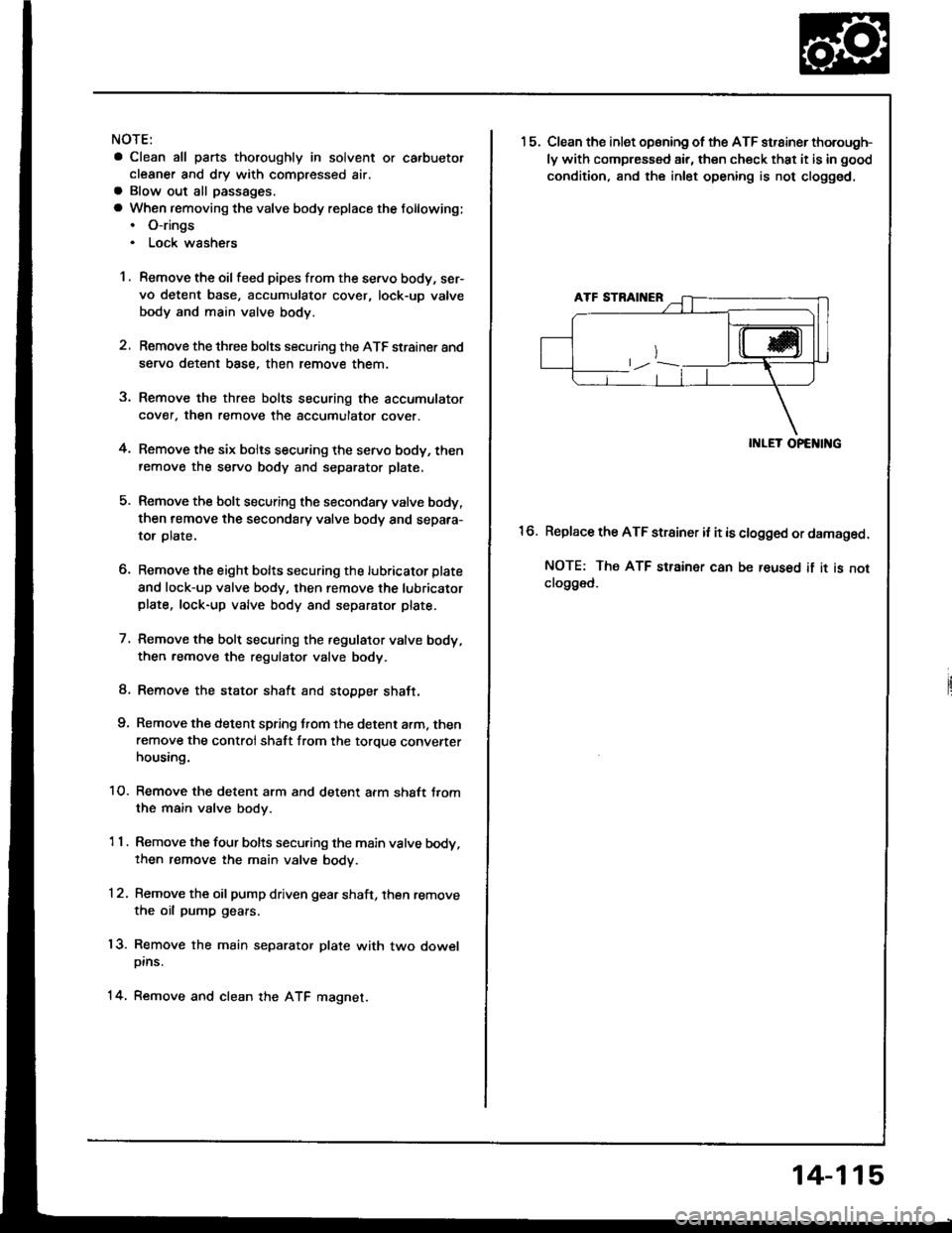
15.Clean the inlet opsning of the ATF strainer thorough-
ly with compressed air, then check that it is in good
condition, and the inlet opening is not clogged.
II{LET OPENING
Replace the ATF strainer it it is clogged or damaged.
NOTE: The ATF strainer can be reused if it is notclo9ged.
16.
14-115
Page 509 of 1413
Valve
Assembly
NOTE:
Coat all parts with ATF belore assemblv.
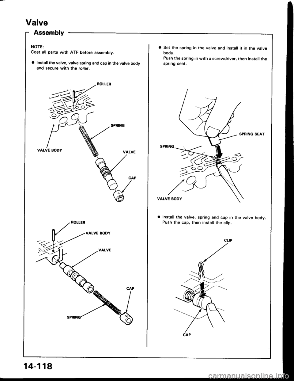
a Install the valve, valve spring and cap in the valve bodyand secure with the 10116r.
ROLLER
VALVE BODY
ROLLER
VALVE EODY
VALVE
5-1-6^<
CAP
14-118
a Set the spring in the valve and install it in the valvebody.
Push the spring in with a screwdriver, then installthespring seat.
SPBING SEAT
VALVE BODY
Install the valve, spring and cap in the valve bodv.Push the cap, then install the cliD,
Page 558 of 1413
Transmission
Cooler Flushing
S!@ ro prevent iniury to tace and eyes, always
wear safety glas$es or a tace shield when using the trans-
mission flusher.
NOTE: This procedure should be performed before rein-
stalling the transmission.
1. Check tool and hoses for wear or cracks before
using.
lf wear or cracks are found, replace the hoses be-
fore using.
2. Using the measuring cup, tillthe tank with 21 ounces
{approximately 213 lulll of biodegradable tlushing
fluid (J35944-20). Do not substitute with any other
fluid.
Follow rhe handling procedure on the fluid container.
Secure the tlusher filler cap and pressurize the tank
with compressed air to between 550-829 kPa(5.6-8.45 kgt/cm,, 80- 120 psi),
NOTE: The air line should be equipped with a water
trap to ensure a dry air system.
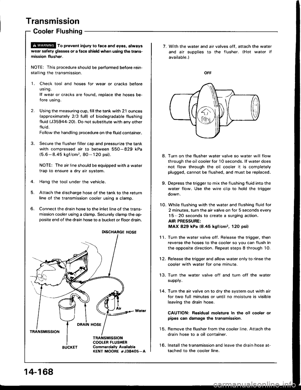
Hang the tool under the vehicle.
Attach the discharge hose of the tank to the return
line of the transmission cooler using a clamp.
Connect the drain hose to the inlet line of the trans-
mission cooler using a clamp. Securely clamp the op-posite end of the drain hose to a bucket or floor drain.
6.
DRAIN HOSE
TRANSMISSION
TRANSMISSIONCOOLER FLUSHEBCommorcially AvailabloKENT MOORE #J38405_A
DISCHARGE HOSE
14-168
BUCKET
7. With the water and air valves off. attach the water
and air supplies to the flusher. (Hot water it
available.)
OFF
8. Turn on the flusher water valve so water will tlow
through the oil cooler for 1O seconds. lf water does
not flow through the oil cooler it is completely
plugged, cannot be flushed, and must be replaced.
9. Depress the trigger to mix the tlushing lluid into the
water tlow. Use the wire clip to hold the trigger
oown.
10. While flushing with the water and flushing fluid for
2 minutes. turn the air valve on for 5 seconds every
15-20 seconds to create a surging action.
AIR PRESSURE:
MAX 829 kPa (8.45 kgt/cm,, 12O psi)
1 1. Turn the water valve off. Release the trigger, then
reverse the hoses to the cooler so you can flush in
the opposite direction. Repeat steps 8 through 1O.
12. Release the trigger and allow water only to rinse the
cooler with water for one minute.
13. Turn the water valve off and turn off the water
supply.
14. Turn the air valve on to dry the system out with air
for two full minutes or until no moisture is visible
leaving the drain hose.
CAUTION: Residual moisture in the oil cooler 01
pipes can damage the transmission.
15. Remove the flusher trom the cooler line. Attach the
drain hose 10 a oil container.
16. lnstallthe transmission and leave the drain hose at-
tached to the cooler line.
Page 559 of 1413
't 7.Make sure the transmission is in @ position.
Then fill the transmission with ATF and run the en-
gins tor 30 saconds or until spproximately ons quart
iB discharged.
Rsmove the drain hose and reconnect the cooler
return hoae to th€ transmission.
Refillth€ trsnsmission with ATF to the prop€r levol.
18.
19.
FILLER CAP
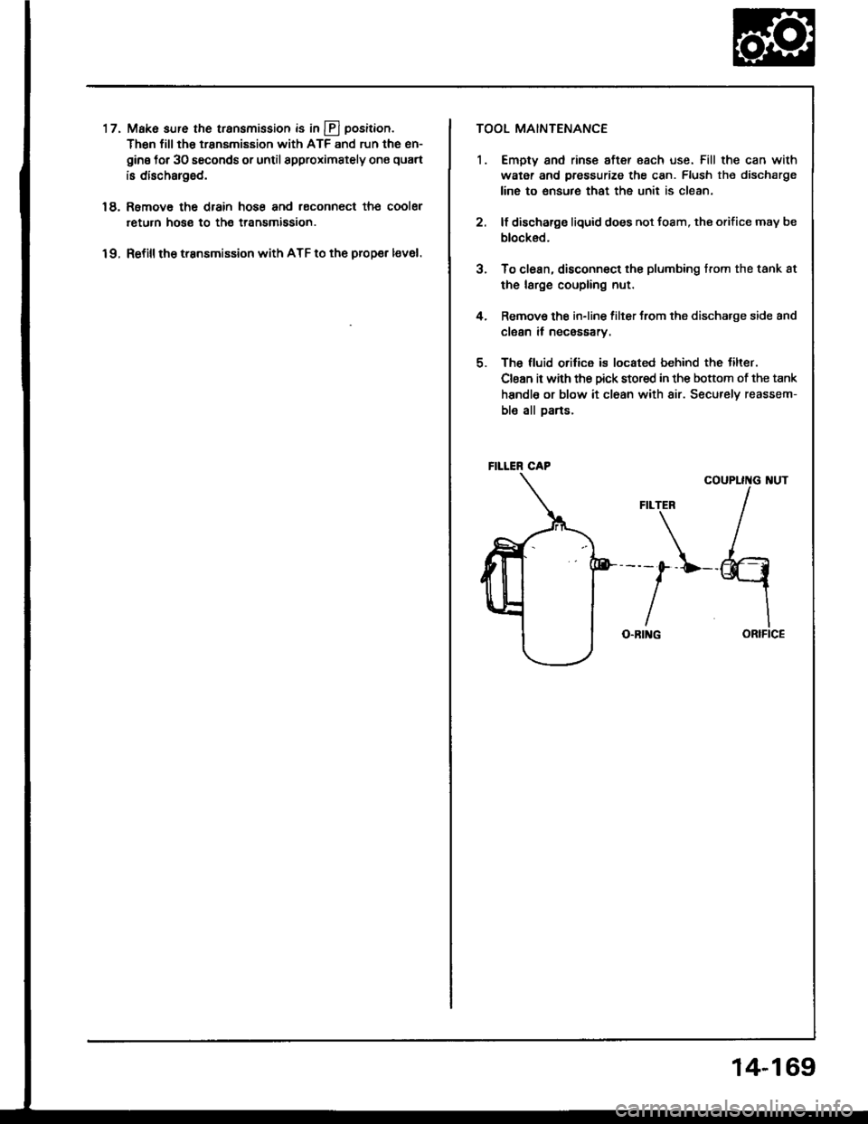
TOOL MAINTENANCE
1. Empty and rinse aftor each use. Fill the can with
water and pressurize the can. Flush the discharge
line to ensure that the unit is clean.
2. lf discharge liquid does not toam, the orifice may be
blocked.
3. To clean, disconnect the plumbing trom the tank 8t
the large coupling nut.
4. Remov€ the in-line filter trom the discharge side and
clean it necossarv.
5. The fluid orilice is located behind the tilter.
Clean it with the Dick stored in the boftom ot the tank
handle or blow it cl6an with air. Securelv reassem-
ble all Darts.
COUPLII{G I{UT
ORIFICE
FILTER
---0--L--
IO.BI G
14-169
Page 639 of 1413
Steering Column
Installation (cont'dl
Finaltorque:22 N.m{2.2 kgf.m, 16lbt.ftl
CAUTION:
. All SRS electrical wiring hrrnossos are covgrod wilhyellow insulation,
. When disconn€cting the SRS wire harness, installthe short connector on the airbag. th€n dbconnoct
the wire harness.
. Replaca the entire alfected SRS harness assembly if
there is an open circuit or damage to tho wiring.
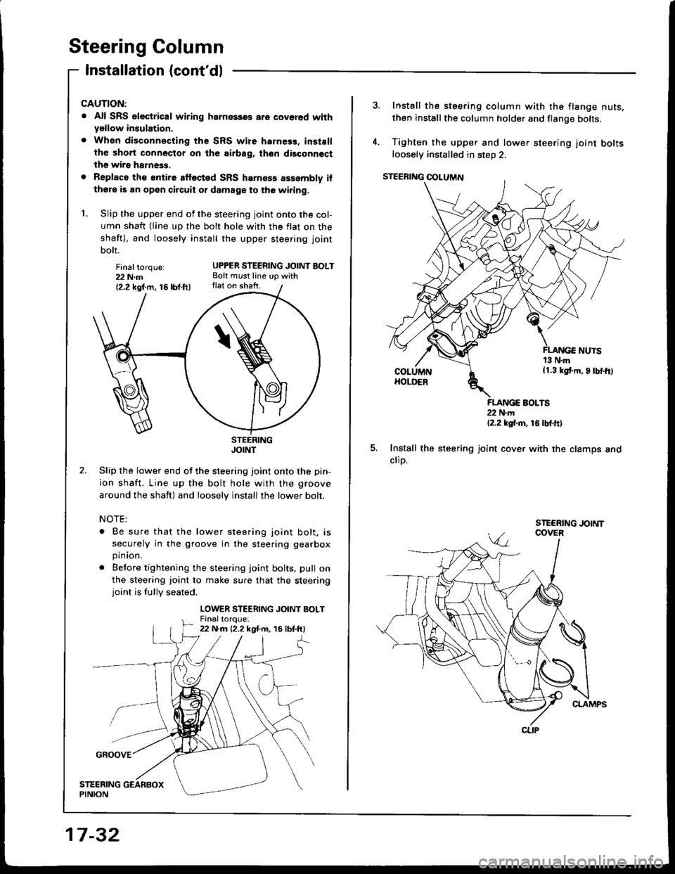
1. Slip the upper end of the steering joint onto the col-
umn shaft {line up the bolt hole with the flat on the
shaft), and loosely install the upper steering joint
bolt.
UPPER STEERING JOINT BOLTBolt must line up withflat on shaft.
STEERINGJOINT
Slip the lower end of the steering joint onto the pin-
ion shaft. Line up the bolt hole with the groove
around the shaft) and loosely jnstallthe lower bolt.
NOTE:
. Be sure that the lower steering joint bolt. is
securely in the groove in the steering gearbox
pinion.
. Before tightening the steering joint bolts, pull on
the sleering joint to make sure that the steeringjoint is fully seated.
LOWER STEERING JOINT BOLTFin6ltoroue:22 N.m {2.2 kgt m. 15 lbf.ftl
17 -32
Install the steering column with the flange nuts,then installthe column holder and flange bolts.
Tighten the upper and lower steering joint boltsloosely installed in steD 2,
FLANGE BOLTS22 N.m12.2 ksi.m, 16 tbtftl
Install the steering joint cover with the clamps andclip.
CLIP
Page 641 of 1413
Power Steering Hoses, Pipes
Replacement
NOTE:
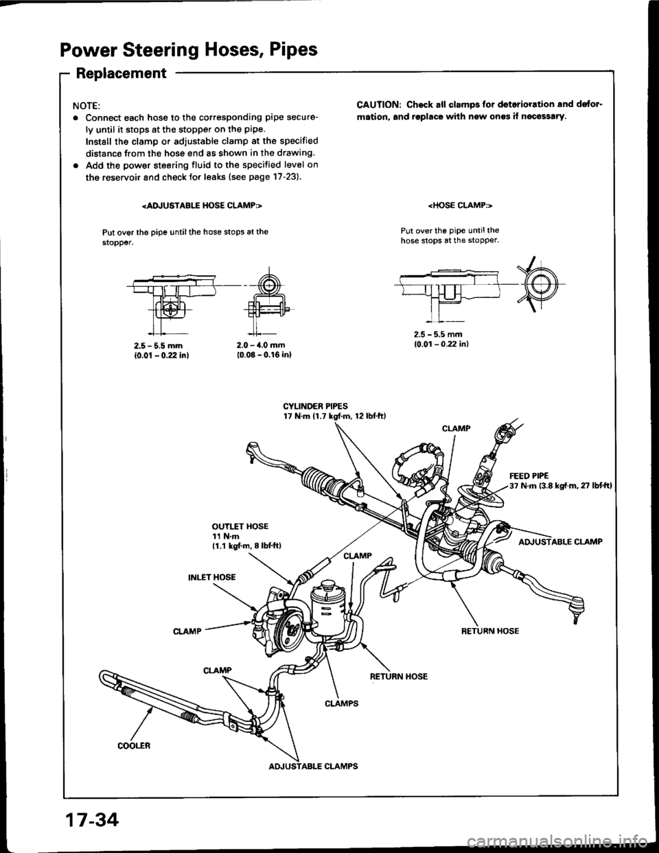
. Connect each hosg to the corresponding pipe securg-
ly until it stops at the stopp€r on the pipe.
Install the clamp or ad,ustable clamp at the specified
distancs from the hose end as shown in the drawing.
. Add the power steering fluid to the specilied level on
the reservoir and check fo. leaks (see page 17-23).
Put ov6r the pipe untilthe hose stops at the$opper.
CAUTION: Chock all clampsfor doterioration 8nd dstor-
mation, and rsplacG with new onss if n6co33!ry,
Put over the pipe untilthehose stops at the stopper.
2.5 - 5.5 mm
{0.01 - 0.22 inl2.0 - 4.0 mm10.08 - 0.16 inl
2.5 - 5.5 mm10.01 - 0.22 in)
OUYI.fT HOSE11 N.m{1.1 kgl.m, 8 lbl.ftl
INI."ET HOSE
ABLE CLAMP
RETURN HOSE
coot"ER
CLAMPS
17 -34
CLAMPS
Page 646 of 1413
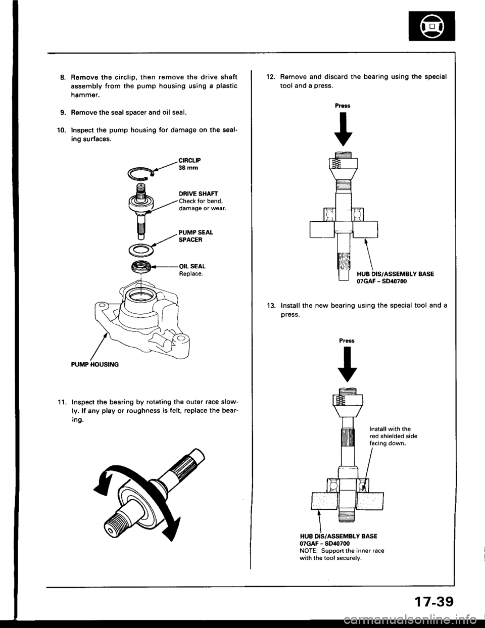
Remov€ the circlip, then remove the drive shaft
assembly from the pump housing using a plastic
namm€r.
Remove the seal spacer and oil seal.
Inspect the pump housing for damage on the seal-
ing surfaces.
/-clRcLlP
Q'/
ra -,"
DRIVE SHAFTfor bend,damage or wear,
PUMP HOUSING
11. lnspect the bearing by rotating the outar race slow-
ly. lf any play or roughness is felt, replace the bear-
ing.
Remove and discard the bearing using the
tool and a gress.
Pra3s
+
special
13.Install the new bearing
press.
I{UB DIS/ASSEMBLY BASE07GAF - SD40700
using the special tool and a
Press
+
Installwith thered shielded sidelacing down.
07GAF - SDis)700NOTE: Support the inner racewith the tool securely.
17-39
Page 651 of 1413
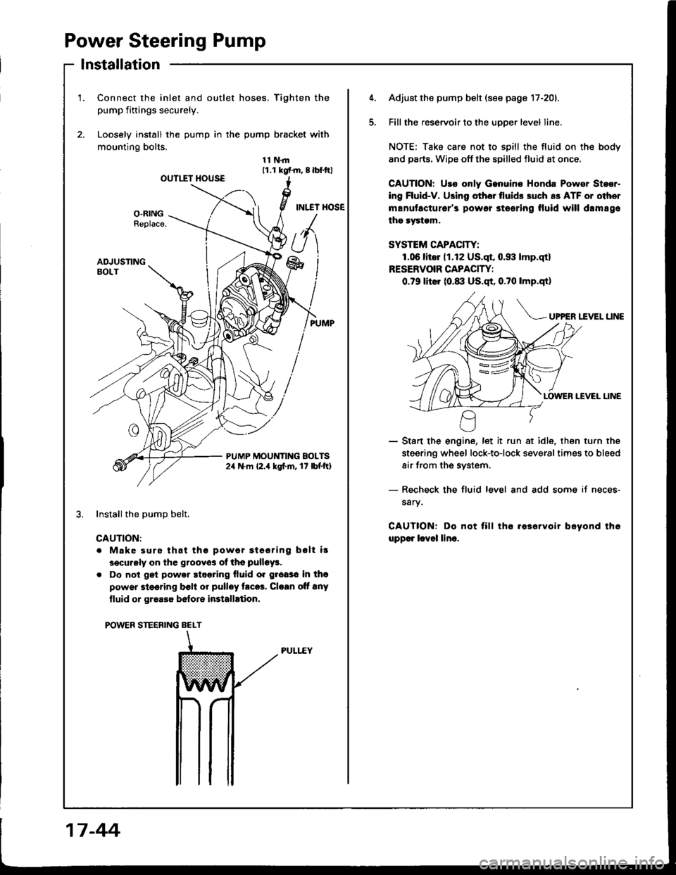
Power Steering Pump
lnstallation
1.Connect the inlet and outlet hoses. Tighten the
pump fiftings securely.
Loosely install the pump in the pump bracket with
mounting bolts.
11N.m11.r kgf.m, 8lbf.ftlOUTIIT HOUSE
INI.TT HOSEO-RINGReplaco.
ADJUSTINGBOLT
PUMP MOUNTING BOLTS2,r N.m {2.4 kgl.m. 17 lbf'ft}
Install the DumD belt.
CAUTION:
. Make surs that thg powor gtooring bslt i!
securgly on the grooyos of ths pulloy!.
. Do not get powor stggring fluid o. groaso in thg
power steering bclt or pulley trc6. Cloan oft 8ny
tluid or groa36 belore installation.
POWER STEERING BELT
PULI..EY
5.
Adjust the pump belt (see page 17-201.
Fill the reservoir to the uoDer level line.
NOTE; Take care not to spill the fluid on the body
and parts. Wipe off the spilled fluid at once.
GAUTION: Uro only Ganuino Honda Powor Stsor.
ing Fluid-V. Using othor tlui& 3uch a3 ATF or oiher
manutacturor's powor steering tluid will drm89e
the rystgm.
SYSTEM CAPACITY:
1.06litor (1.12 US.qt, 0.93 lmp.qt)
RESERVOIR CAPACIW:
0.79 litor (0.1|:| US.qt, 0.?0 lmp.qtl
UP?ER I.fVEL LINE
IEVEI LINE
- Start the engine, let it run at idle, then turn the
steering wheel lock-to-lock severaltimes to bleed
air from the system.
- Recheck the fluid level and add some if neces-
s8ry.
CAUTIONT Do not fill tha .63ervoir boyond th6
upp€r lcvol lino.
17 -44
Page 662 of 1413
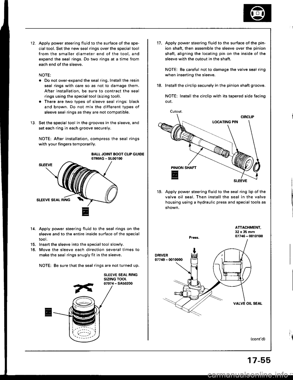
Apply power steering fluid to the surface of the spe-
cial tool. Set the new seal rings over the special tool
from the smaller diameter end of the tool, and
expand the seal rings. Do two rings at a time from
each end of the sleeve,
NOTE:
. Do not over-expand the seal ring. Install the resin
seal rings with care so as not to damage them.
After installation, be sure to contract the seal
rings using the specialtool {sizing tool}.
. There are two types of sleeve seal rings: black
and brown. Do not mix the different types of
sleeve seal rings as they are not compatible.
Set the special tool in the grooves in the sleeve. and
set each ring in each groove securely.
NOTE: After installation, compress the seal rings
with your fingers temporarily.
BALL JOINT BOOT CLIP GUIDEo?MAG - SL001d)
14. Apply power steering fluid to the seal rings on the
sleeve and to the entire inside surface of the special
tool.
15. Insert the sleeve into the specialtool slowly.
16. Move the sl€eve each direction several times to
make the seal rings snugly fit in the sleeve.
NOTE: Be sure that the seal rings are not turned up.
SLEEVE SEAL RINGSIZING TOOL
13.
07974 - 5450200
Cutout,
't7.Apply power steering fluid to the surface ol the pin-
ion shaft, then assemble the sleeve over the pinion
shaft, aligning the locating pin on the inside of the
sleeve with the cutout in the shaft,
NOTE: Be careful not to damage the valve seal ring
when inserting the sleeve.
Install the circlip securely in the pinion shaft groove.
NOTE: Install rh€ circlip with its tapered side facing
OUI.
19. Apply power steering fluid to the seal ring lip of the
valve oil seal. Then install the seal in the valve
housing using a hydraulic press and special tools as
shown.
18.
ATTACHMENT,32x35mm077{6 - 0010100
{cont'd)
VALVE OIL SEAL
17-55
ir