torque HONDA INTEGRA 1994 4.G Repair Manual
[x] Cancel search | Manufacturer: HONDA, Model Year: 1994, Model line: INTEGRA, Model: HONDA INTEGRA 1994 4.GPages: 1413, PDF Size: 37.94 MB
Page 505 of 1413
![HONDA INTEGRA 1994 4.G Repair Manual Torque Gonverter Housing/Valve Body
Removal
\LOCK-UP VALVE llB.DY\u
Bolts, 7
DOWEL PIN
otLFEEDPIPES
A
Ll
ll|i
|]V
OII- FEED PIPES
LOCK-UP SEPARATORPI.ATE
TOR COVER
OIL FEEO PIPE
8oll3.3
ATF STRAINER
S HONDA INTEGRA 1994 4.G Repair Manual Torque Gonverter Housing/Valve Body
Removal
\LOCK-UP VALVE llB.DY\u
Bolts, 7
DOWEL PIN
otLFEEDPIPES
A
Ll
ll|i
|]V
OII- FEED PIPES
LOCK-UP SEPARATORPI.ATE
TOR COVER
OIL FEEO PIPE
8oll3.3
ATF STRAINER
S](/img/13/6067/w960_6067-504.png)
Torque Gonverter Housing/Valve Body
Removal
\LOCK-UP VALVE llB.DY\u
Bolts, 7
DOWEL PIN
otLFEEDPIPES
A
Ll
ll|i
|]V
OII- FEED PIPES
LOCK-UP SEPARATORPI.ATE
TOR COVER
OIL FEEO PIPE
8oll3.3
ATF STRAINER
SERVO DETENTBASEREGULATOR VALVEAODY
OIL FEED PIPES
DOWEL PIN
OIL PUMP DRIVEN GEAR SHAFT
OIL PUMP DRIVEN
SECONDARY VALVEBODY
DOWEL PIN
SECONDARY SEPARATORPLATE
SUCTION PIPECOLLAR
MAIN S€PARATORPLATE
ft-- rrr urcler
TOROUE CONVERTERHOUSING
8olts, 4 Boll
MAIII VALVEBODY
14-114
Page 506 of 1413
NOTE:
a Clean all parts thoroughly in solvent or carbuetor
cleaner and dry with compressed air.a Blow out all passages.
a When removing the valve body replace the following:. O-rings. Lock wsshers
1 . Remove the oil feed pipes from the servo body, s€r-
vo detent base, accumulatof cover, lock-uD valve
body and main valve body.
2, Remove the three bolts securing the ATF strainer and
servo detent base, then remove them.
3. Remove the three bolts securing the accumulator
cover. then remove the accumulator cover.
4. Remove the six bolts secu.ing the servo body, then
remove the servo body and separator plate.
5. Remove the bolt securing the secondary valve body,
then remove the secondary valve body and separa-
tor plate.
6. Remove the eight bolts securing the lubricator plate
and lock-up valve body, then remove the lubricatorplate, lock-up valve body and separator plate.
7. Femove the bolt securing the.egulator valve body,
then.emove the regulator valve body.
8. Remove the stator shaft and stopper shaft.
9. Remove the detent spring t,om the detent arm. thenremove the control shaft from the torque convenerhousing.
1O. Remove the detent arm and detent afm shaft t.om
the main valve bodv.
1 1 . Remove the four bolts secu.ing the main valve body,then remove the main valve body.
12. Remove the oil pump driven gear shaft, then remove
the oil pump gears.
'13. Remove the main separator plate with two dowelDtns.
14, Remove and clean the ATF magnet.
15.Clean the inlet opsning of the ATF strainer thorough-
ly with compressed air, then check that it is in good
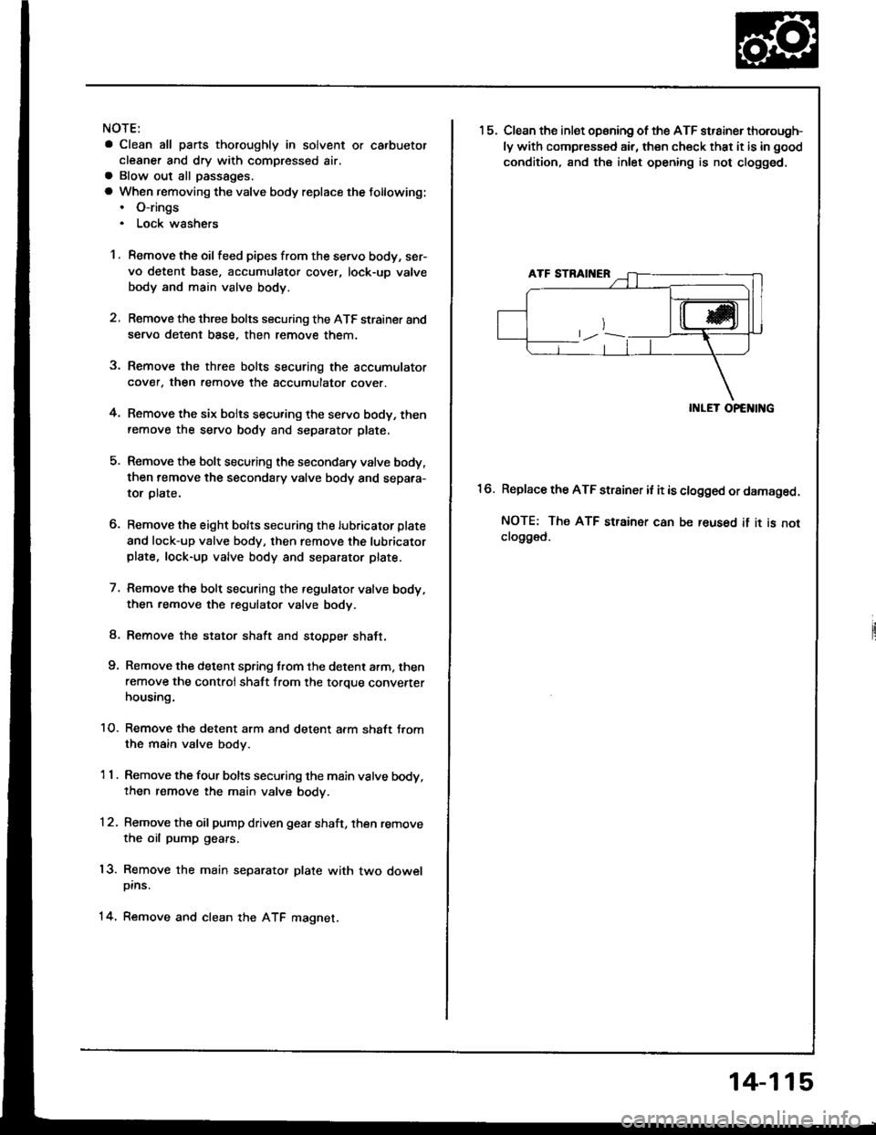
condition, and the inlet opening is not clogged.
II{LET OPENING
Replace the ATF strainer it it is clogged or damaged.
NOTE: The ATF strainer can be reused if it is notclo9ged.
16.
14-115
Page 513 of 1413
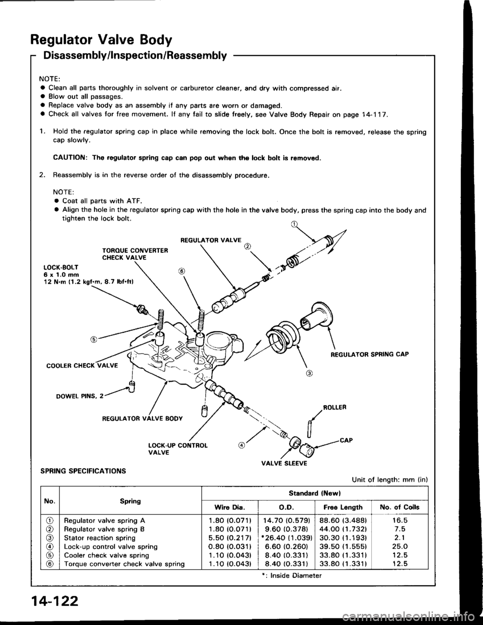
Regulator Valve Body
Disassembly/lnspection/Reassembly
NOTE:
a Clean all pans thoroughly in solvent or carburetor cleaner, and dry with compressed ait.a Blow out all passages.
a Replace valve body as an assembly it any parts are worn or damaged.a Check all valves for free movement. lf any fail to slide freely, see Valve Body Repair on page 14-117.
1. Hold the .egulator spring cap in place while removing the lock bolt. Once the bolt is removed. release the spring
cap slowlv.
CAUTION: The .egulator spring c8p can pop out whsn the lock bolt is removod.
2. Reassembly is in the reverse order of the disassembly procedute.
NOTE:
. Coat all pans with ATF.
a Align the hole in the regulator spring cap with the hole in the valve body, press the spring cap into the body andtighten the lock bolt.
LOCK.BOLT6 x 1.0 mm12 N.m (1.2 kgl.m, 8.7 lbf.ftl
REGULATOR SPRING CAP
COOLER CHECK
OOWEL PINS, 2
ROLLER
SPRING SPECIFICATIONS
Unit of length: mm (in)
../
I',.-2" ll"%=
VALVE SLEEVE
t,-V
,*6t'"
REGULATOR VALVE
REGULATOR VALVE BODY
No.Spring
Standard (New)
Wiro Dia.o.D.Free LonglhNo. of Coils
o/a
@
\9/
Regulator valve spring A
Regulator valve spring B
Stator reaction spring
Lock-up control valve spring
Cooler check valve spring
Torque converter check valve spring
1.80 (O.O71)
1.80 (0.071)
5.50 (O.2171
o.80 (o.o31)
1 .10 (0.043)
1 .10 (O.O43t
14.70 (O.5791
9.60 (0.378)'26.40 (1.O39)
6.60 (O.260)
8.40 (O.331)
8.40 (0.331)
88.60 (3.488t
44.OO t't.7321
30.30 (1 .1 93t
39.50 (1.555)
33.80 (1 .331 I
33.80 (1 .331 )
16.5
2.1
25.O'l2.5
12.5
14-122
lnside Diameter
Page 521 of 1413
Mainshaft
Inspection
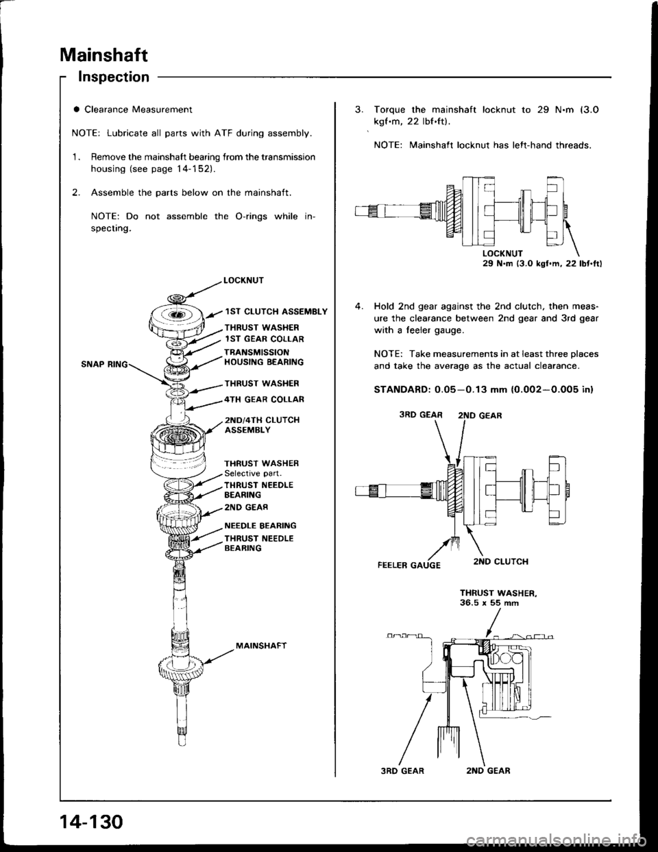
a Clearance Measurement
NOTE: Lubricate all parts with ATF during assembly.
1 . Remove the mainshaft bearing lrom the transmission
housing (see page 14-152).
2. Assemble the parts below on the mainshaft.
NOTE: Do not assemble the O-rings while in-
specting.
LOCKNUT
/ 1ST CLUTCH ASSEMBLY
THRUST WASHER
lST GEAR COLLAR
TBANSMISSIONHOUSING BEARING
THRUST WASHER
4TH GEAR COLLAR
2ND/4TH CLUTCHASSEMBLY
THRUST WASHERSelective part.
TI{RUST NEEDLEBEARING
2ND GEAR
NEEDLE BEARING
THRUST NEEOLEBEARING
MAINSI.IAFT
14-130
3RD GEAR2ND GEAR
Torque the mainshaft locknut to 29 N.m (3.0
kgf .m, 22 lbf.ft).
NOTE: Mainshaft locknut has lett-hand threads.
29 N.m (3.0 kgl.m, 22 lbt.ft)
4. Hold 2nd gear against the 2nd clutch. then meas-
ure the clearance between 2nd gear and 3rd gear
with a feeler gauge.
NOTE: Take measurements in at least three Dlaces
and take the average as the actual clea.ance.
STANDARD: 0.05-0.13 mm {0.002-0.005 inl
THRUST WASHER-36.5 x 55 ftm
3RD GEAR 2ND GEAR
Page 526 of 1413
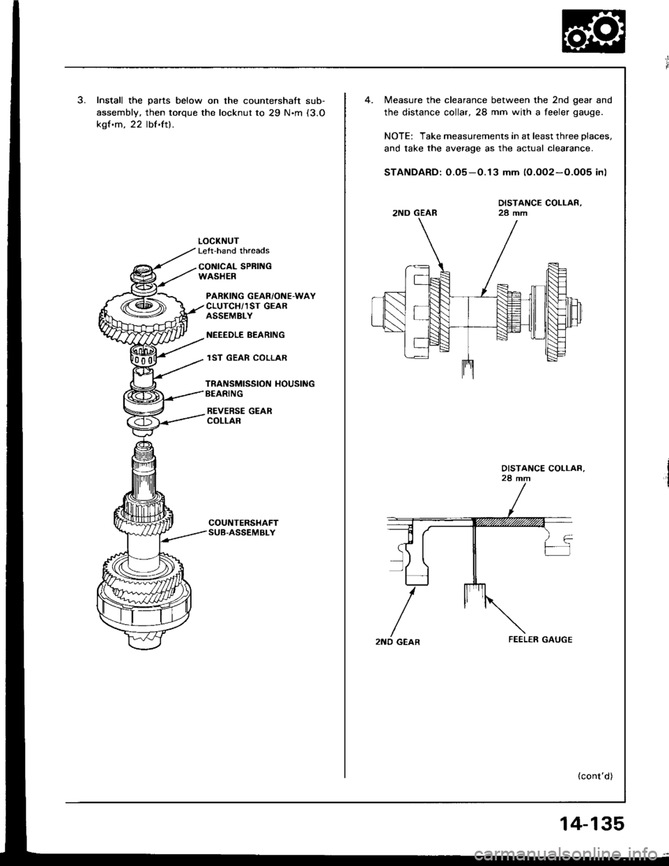
Install the parts below on the countershaft sub-
assembly, then torque the locknut to 29 N'm (3.O
kgf.m, 22 lbf.ft).
LOCKNUTLeft-hand threads
CONICAL SPRI GWASHER
PARKING GEAR/ONE-WAYCLUTCH/1ST GEARASSEMBLY
NEEEDLE BEARING
lST GEAR COLLAR
TRANSMISSION HOUSINGBEARING
REVERSE GEARCOLLAR
Measure the clearance between the 2nd gear and
the distance collar, 28 mm wilh a feeler gauge.
NOTE: Take measurements in at least three places.
and take the average as the actual clearance.
STANDARD: O.O5-0.13 mm (0.OO2-O.O05 in)
DISTANCE COLLAR,28 mm2ND GEAR
2ND GEAR
(cont'd)
14-135
Page 541 of 1413
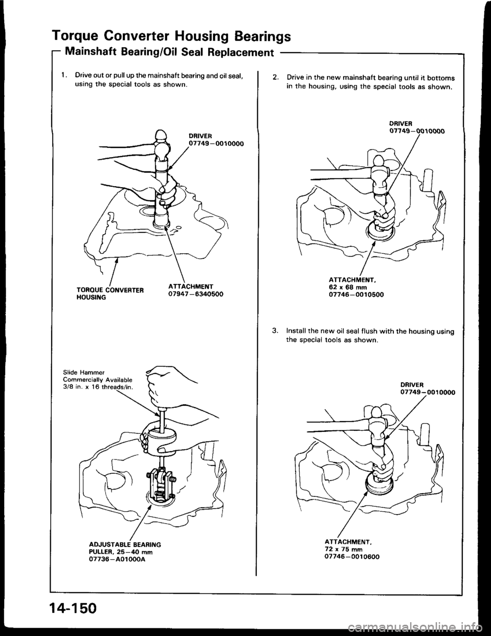
Torque Converter Housing Bearings
Mainshaft Beadng/Oil Seal Replacement
1 . Drive out or pull up the mainshaft bearing and oil seal,using the special tools as shown.
Slide HammerCommercially Available3/8 in. x 16
07749 -OOIOOOO
14-150
2.Drive in the new mainshaft bearing until it bottomsin the housing, using the special tools as shown.
3.Installthe new oil seal flush with the housing usingthe sDecial tools as shown.
ATTACHMENT,62x68mm07746-0010500
ATTACHMENT,72x75mm07746-0010600
DRIVEN
Page 547 of 1413
2.
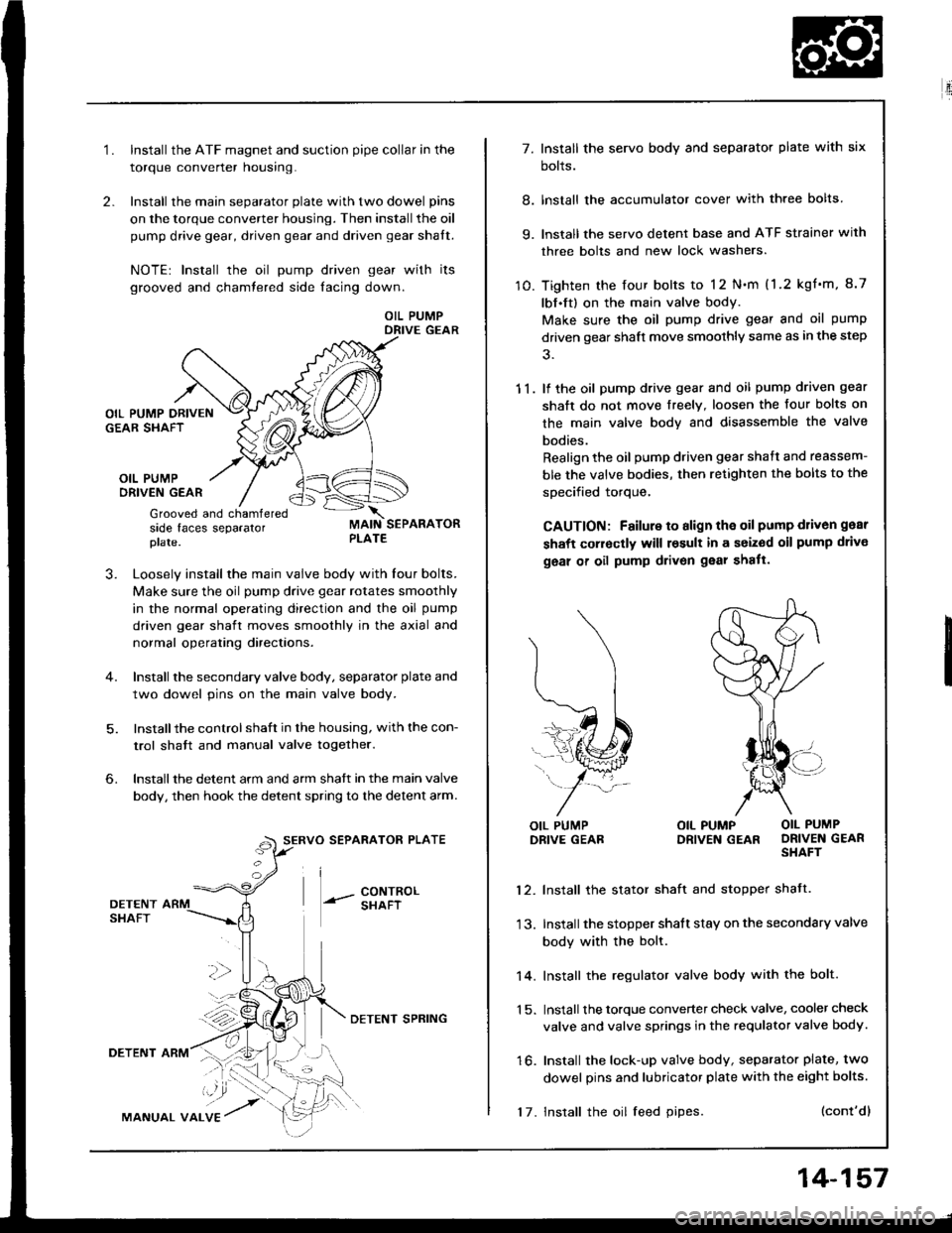
1.Install the ATF magnet and suction pipe collar in the
torque converter nousrng.
Install the main separator plate with two dowel pins
on the torque converter housing. Then install the oil
pump drive gear, driven gear and driven gear shalt.
NOTE| Install the oil pump driven gear with its
grooved and chamtered side facing down.
OIL PUMPDRIVE GEAR
OIL PUMPORIVEN GEAR
Grooved and chamferedside faces separatorplate.
J.Loosely install the main valve body with Iour bolts.
Make sure the oil pump drive gear rotates smoothly
in the normal operating direction and the oil pump
driven gear shaft moves smoothly in the axial and
normal operating directaons.
Install the secondary valve body, separator plate and
two dowel pins on the main valve body.
Installthe control shaft in the housing, with the con-
trol shatt and manual valve togelher.
Install the detent arm and arm shatt in the main valve
body, then hook the detent spring to the detent arm.
SERVO SEPARATOR PLATE
--- 8ixli"'
6.
36
DETENTSHAFT
DETENT ARM
MANUAL VALVE
DETENI SPRING
17. Install the oil feed pipes.
14-157
E'.:
7. Install the servo body and separator plate with six
bolts.
8. lnstall the accumulator cover with three bolts
9. lnstall the servo detent base and ATF strainer with
three bolts and new lock washers.
10. Tighten the four bolts to 12 N.m (1.2 kgf'm, 8.7
lbf.ft) on the main valve body.
Make sure the oil pump drive gear and oil pump
driven gear shaft move smoothly same as in the step
11. lf the oil pump drive gear and oil pump driven gear
shaft do not move freelY. loosen the four bolts on
the main valve body and disassemble the valve
bodies.
Realign the oil pump driven gear shaft and reassem-
ble the valve bodies, then retighten the bolts to the
specified torque,
CAUTION: Failure to align the oil pump d1iv6n gear
shaft corroctly will result in a seized oil pump drivo
geal of oil pump drivon gear shatt.
l\
(...l
=..�N
L,1ffi#
j-*/:
OIL PUMPDRIVE GEABOIL PUMP OIL PUMPDRIVEN GEAR DRIVEN GEARSHAFT
12. Install the stator shaft and stopper shatt.
13. Install the stopper shatt stay on the secondary valve
body with the bolt.
14. Install the regulator valve body with the bolt.
1 5. Install the torque converter check valve, cooler check
valve and valve springs in the requlator valve body.
16. Install the lock-up valve body, separator plate, two
dowel pins and lubricator plate with the eight bolts.
(cont'dl
Page 549 of 1413
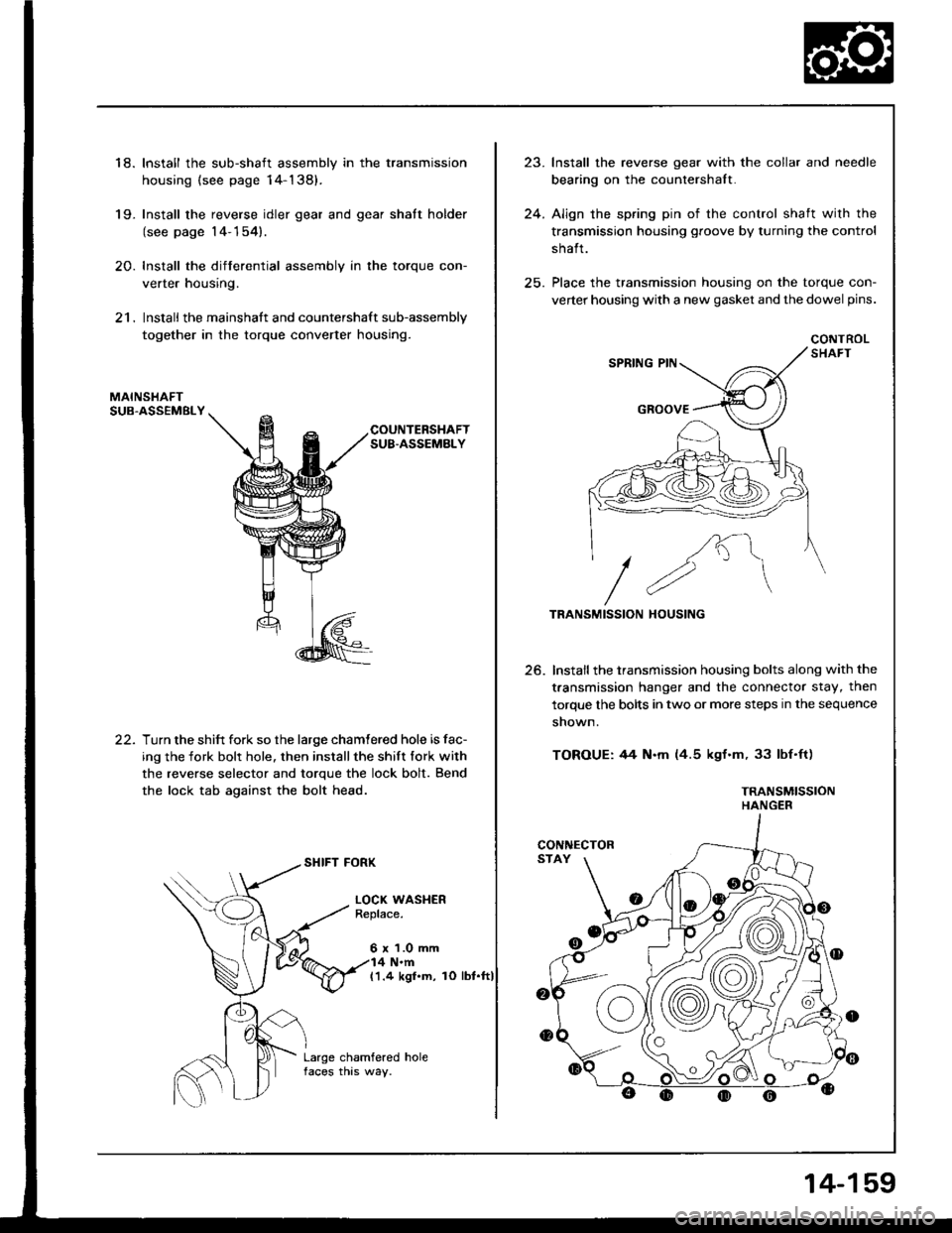
18. Install the sub-shaft assembly in the transmission
housing {see page 14-138).
19- Install the reverse idler gear and gear shatt holder
(see page 14-154).
20. Install the differential assembly in the torque con-
verter housing.
21. Install the mainshaft and countershaft sub-assembly
together in the torque converter housing.
MAINSHAFTSUB.ASSEMBLY
COUNTERSHAFTSUB.ASSEMBLY
22.Turn the shift fork so the large chamtered hole is fac-
ing the fork bolr hole. then installthe shift fork with
the reverse selector and torque the lock bolt. Bend
the lock tab against the bolt head.
SHIFT FORK
LOCI( WASHERReplace.
6 x 1.0 mm4 N.m(1.4 kgl.m, rO lbt.ft)
Large chamfered holefaces this way.
,,1
24.
lnstall the reverse gear with the collar and needle
bearing on the countershalt.
Align the spring pin of the control shaft with the
transmission housing groove by turning the control
shalt.
Place the transmission housing on the torque con-
verter housing with a new gasket and the dowel pins.
CONTROL
/K"\
//2"\TRANSMISSION HOUSING
Install the transmission housing bolts along with the
t.ansmission hanger and the connector stay, then
torque the bolts in two or more steps in the sequence
shown.
TOROUE: 44 N.m (4.5 kgf.m, 33 lbf'ft)
TRANSMISSIONHANGER
25.
CONNECTOR
14-159
Page 550 of 1413
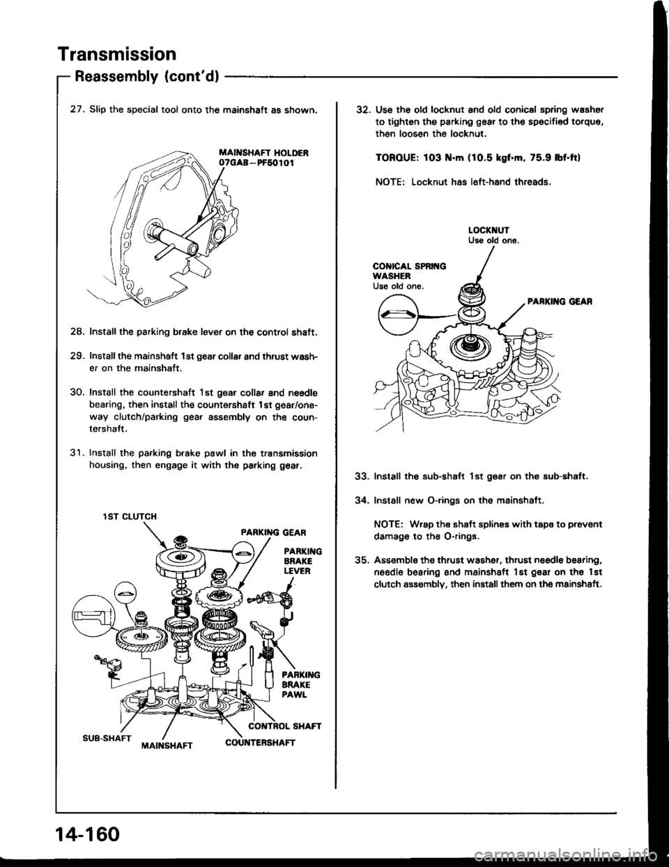
Transmission
Reassembly (cont'dl
SUB-SHAFT
27. Slip the special tool onto the mainshaft as shown.
MAII{SHAFT HOLDERoTGAa - PF5010I
Install the parking b.ake lever on the control shaft.
Installthe mainshaft 1st g6ar collar and thrust wash-
er on the mainshaft.
Install the countershaft 1st gear collar and n6€dls
bearing, then install the count€rshatt 1st gear/one-
way clutch/parking gea, assembly on the coun-
tershalt.
Install the parking b.ake pawl in th€ transmission
housing, then engage it with the parking gear.
PARKI''IG GEAR
PARTI GARAKELEVER
24.
29.
30.
31.
lST CLUTCH
14-1 60
MAIt{SHAFTCOU TERSHAFT
32. Use th6 old locknut and old conicsl spring washot
to tighten th€ parking gear to th€ sp€cifi€d torque,
then loosen the locknut.
TOROUE: 103 .m (1O.5 kgf.m, 75.9 lbf'ftl
NOTE: Locknut has left-hand threads.
PARKII{G GEAR
Install the sub-shaft lst gear on thg sub-shaft.
Install new O-rings on the mainshaft.
NOTE: Wrap the shaft splines with tspa to prevont
damago to the O-rings.
Assemblo th€ thrust wash6r, thrust naedle bearing,
needle bearing and msinshsft lst gear on tho lst
clutch assombly, then install them on the mainshaft.
33.
34.
Page 551 of 1413
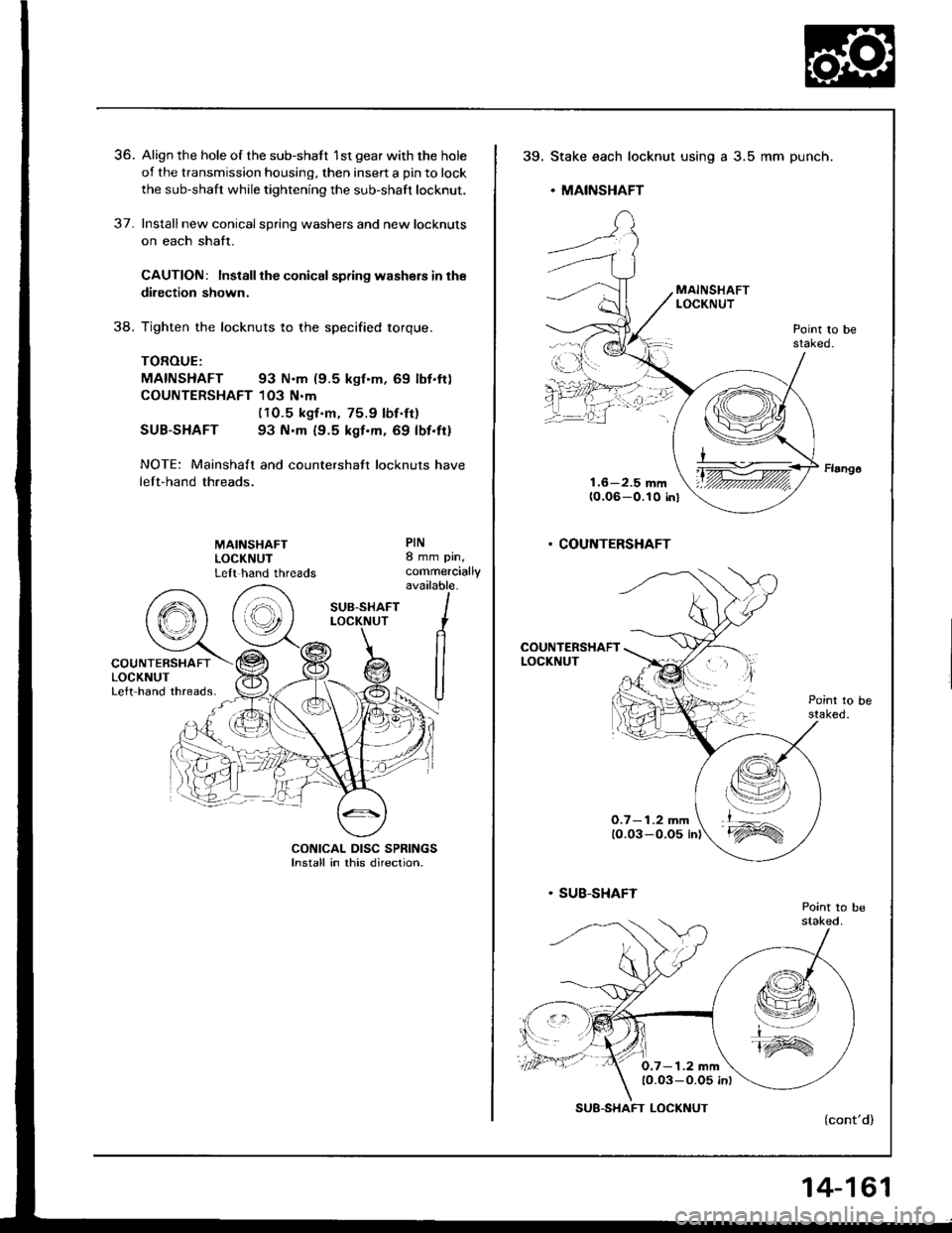
36. Align the hole of the sub-shaft 1st gear with the hole
of the transmission housing, then insert a pin to lock
the sub-shaft while tightening the sub-shaft locknut.
37. Installnew conicalspring washers and new locknuts
on each shaft.
CAUTION: Install the conical spdng washers in the
dilection shown.
38. Tighten the locknuts to the specified torque.
TOROUE:
MAINSHAFT 93 N.m (9.5 kgf'm, 69 lbf.ft)
COUNTERSHAFT 103 N.m(1O.5 kgf.m, 75.9 lbf.ft)
SUB-SHAFT 93 N.m (9.5 kgf.m. 69 lbf.fi)
NOTE: Mainshalt and countershaft locknuts have
left-hand threads.
CONICAL DISC SPRINGSlnstall in rhis direcrion.
39.Stake each locknut using
. MAINSHAFT
a 3.5 mm punch.
. COUNTERSHAFT
O,7- 1.2 mm
0.7- 1.2 mm1O.03-O.05 in)
SUB-SHAFT LOCKNUT
14-161