torque HONDA INTEGRA 1994 4.G Manual PDF
[x] Cancel search | Manufacturer: HONDA, Model Year: 1994, Model line: INTEGRA, Model: HONDA INTEGRA 1994 4.GPages: 1413, PDF Size: 37.94 MB
Page 666 of 1413
41.
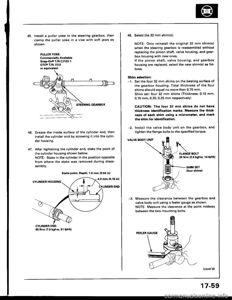
Install a puller yoke to the steering gearbox, then
clamp the puller yoke in a vise with soft jaws as
shown.
PULLER YOXE:Commcrcirlly AvrihbloSn.p-Ono T/N Cr123-lorco T/N 7372or aquivrlani
Grease the inside surface of the cylinder end, then
install the cylinder end by screwing it into the cylin-
der housing.
After tightening the cylinder end, stake the point of
the cylinder housing shown below.
NOTE: Stake in the cylinder in the position opposite
from where the stake was removed during disas-
semblv.
Strke point, D.pth: 1.0 mm (0.04 inl
4.0 mm 10.15 inlCYLINDER HOUSING
CYLINDER END
CYLINOER69 N.m 17.0 kgf.m, 51 lbtft)
,t8. Select the 32 mm shim(s).
NOTE: Only reinstall the original 32 mm shim(s)
when the steering gearbox is reassembled without
replacing the pinion shaft, valve housing, and gear-
box housing with new ones.
lf the pinion shaft, valve housing, and gearbox
housing are replaced, select the new shim{s) as fol-
rows.
Shim r€lection:-'1. Set the four 32 mm shims on the b€aring surface of
the gearbox housing. Total thickness of the four
shims should eoual no more than 0.70 mm.
Shim set: tour 32 mm shims (Thickness: 0.10 mm,
0.15 mm, 0.20, 0.25 mm respectivelyl
CAUTION: The tour 32 mm shimr do not hlva
thlckn$s idcntitication mukt. Mo!3ur. tho thicl-
oa33 of rach 3him using a miclomctrl, and mlrk
tho shim lor id6ntific8tion.
-2. Install the valve body unit on the gearbox, and
tighten the flange bolts to the specitied torque
VALVE BODY UNIT
FLANGE BOLT20 N.m {2.o kgtm, 14lbt'ftl
SHIM SET{foul thim.)
Measure the clearance between the gearbox and
valve body unit using a feeler gauge as shown.
NOTE: Measure the clearance at the point midway
between the two mounting bolts.
(cont'd)
17-59
Page 667 of 1413
Steering Gearbox
Reassembly lcont'd)
-4. Determine the requifed thickness of the 32 mm
shims by subtracting the clearance obtained in thestep -3 from the total thickness of the four shims.(Total thickness of the 4 shims) - (Clearance) =
Required thickness of the shims
NOTE: Select the shims so that th6 total thicknessis close to, but less than the required thickness.
Exampls:
Measu.ement is 0.28 mm (0.011 in):
0.70 - 0.28 = 0.42 mm (0.028 - 0.011 = 0.0't7 in)
The selected shims should be 0.25 mm (O.O1O in) and0.15 mm (0.005 in) in thickness.
lf the required shim thickness is 0.lO mm or less, no
shims are necessary.
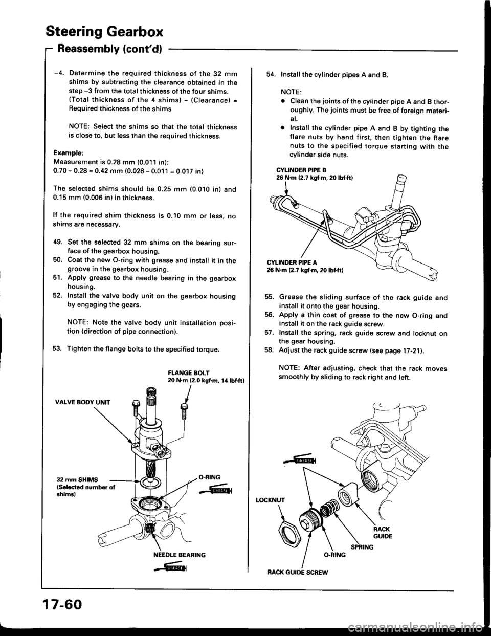
i[9. Set the selected 32 mm shims on the bearing sur-face of the g€arbox housing.
50, Coat the new O-ring with gresse and install it in thegroove in the gearbox housing.
Apply grease to the needle bearing in the gearbox
housing.
Install the valve body unit on the gearbox housing
by engaging the gears.
NOTE: Note the valve body unit installation posi-
tion (direction of pipe connection).
Tighten the flange bolts to the specified torque.
FLANGE BOLT20 N.m (2.0 kgt m, 14lbf.ft)
VALVE BODY UNIT
ct.
O-RING
-ffiti
NEEOLE BEARING
_#{
17-60
BACK GUIDE SCREW
54. Installthe cylind6r pipes A and B.
NOTE:
. Clean the joints ofthe cylinder pipe A and B tho.-oughly. The joints must be free of foreign mat€.i-
at,
o Install the cylinder pipe A and B by tighting theflare nuts by hand first, then tighten the flarenuts to the specified torque starting with thecylinder side nuts.
CYLINDER PIPE B
Grease the sliding surface of the rack guide andinstall it onto the gear housing.
Apply a thin coat of grease to the n€w O-ring andinstall it on the rack guide screw.
Install the spring, rack guide screw and locknut onthe gear housing.
Adjust the rack guide screw (see page l7-21).
NOTE: After adjusting, check that the rack movessmoothly by sliding to rack right and left.
LOCKNUT
-6t
26 N.m (2.7 kg{.m,20lbtft)
Page 672 of 1413
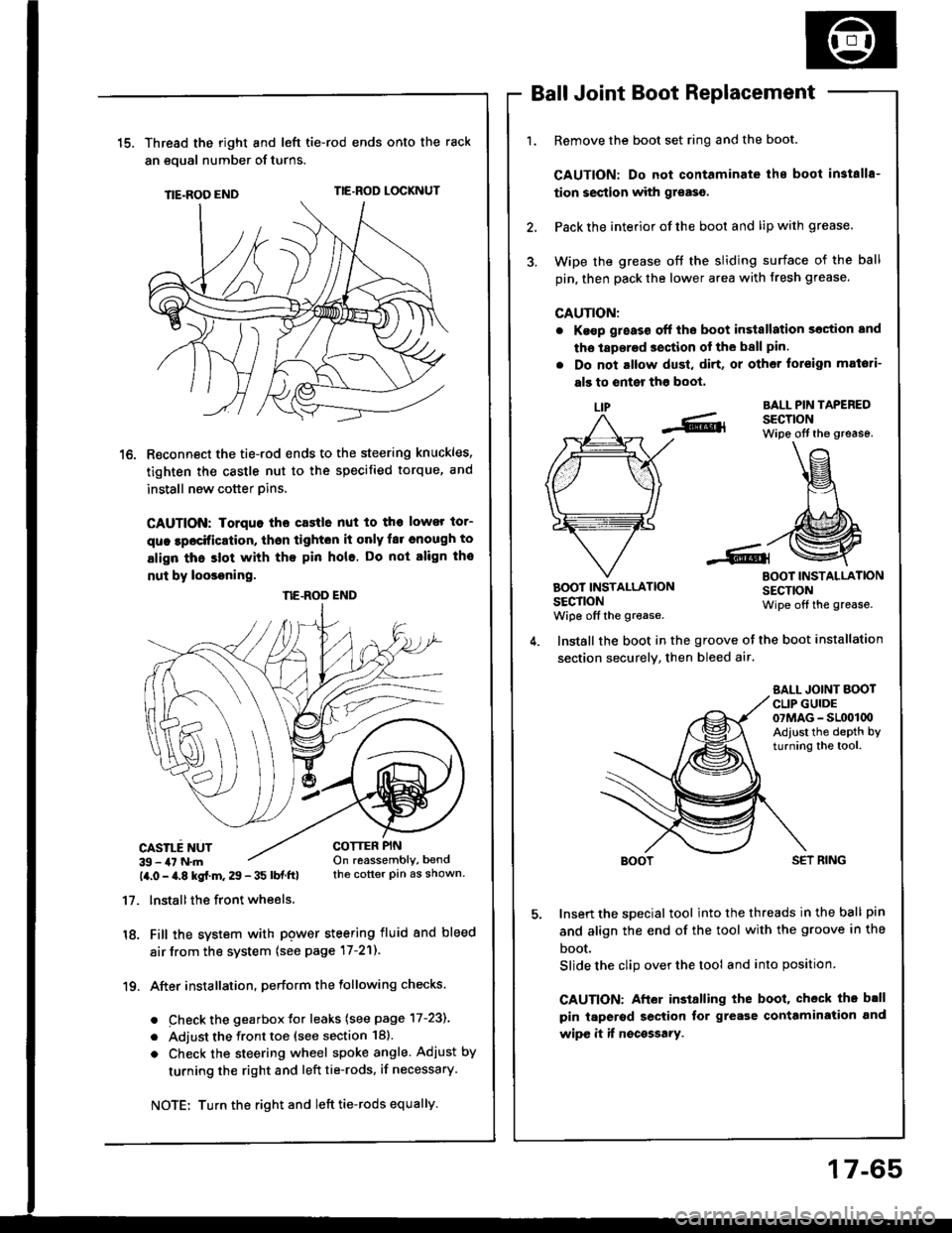
15.Thread the right and lefi tie-rod ends onto the rack
an eoual number of turns.
TIE-ROO ENDTIE.ROD LOCKNUT
R€connect the tie-rod ends to the steering knuckles,
tighten the castle nut to the specified torque, and
install new cotter pins.
CAUTION: Iorquo tho castle nut to tho lower tor-
que lpocification, thsn tighton it only far cnough to
align thc slot with tho pin hole. Do not align tho
nut by loosoning.
CASILE NUT39 - 47 N.m14.0 - a.8 kgf.m. 29 - 35 lbf ftl
17. lnstallthe front wheels.
18. Fill the system with pgwer steering fluid and bleed
air from the system (see page 17-21).
19. After installation. perform the following checks.
. Check the gearbox Jor leaks (see page 17-231
. Adjust the front toe (see section 18).
o Check the steering wheel spoke angle. Adjust by
turning the right and left tie-rods, if necessary.
Ball Joint Boot Replacement
Remove the boot set ring and the boot.
CAUTION: Do not contaminate ihe boot in3talls-
tion section with gr€aso.
Pack the interior of the boot and lip with grease.
Wipe the grease off the sliding surface of the ball
pin, then pack the lower area with fresh grease.
CAUTION:
. Ke€p g;eass off the boot in3tallation section and
tho laperad section of the ball pin.
. Do not altow dust, di.t, or other toreign mat6ti-
als to enter tho boot,
LIPBALL PIN TAPEREDSECTIONWipe off the grease.
BOOT INSTALLATIONSECTIONwiDe off the grease.
BOOT INSTALLATIONSECTIONWipe off the grease.
COTTER PINOn reassembly, bendthe cotter pin as shown.
Install the boot in the groove ot the boot installation
section securely, then bleed air.
SALL JOINT BOOTCLIP GUIDE07MAG - SL(x)l00Adiust the depth byturning the tool.
SET RING
Insert the special tool into the threads in the ball pin
and align the end of the tool with the groove in the
boot.
Slide the clip over the tool and into position
CAUTION: After installing the boot, check th. b.ll
pin taperod section tor grease contamiration and
wipe it if nocossary.
NE.ROD END
Turn the right and left tie-rods equally.
17-65
Page 1034 of 1413
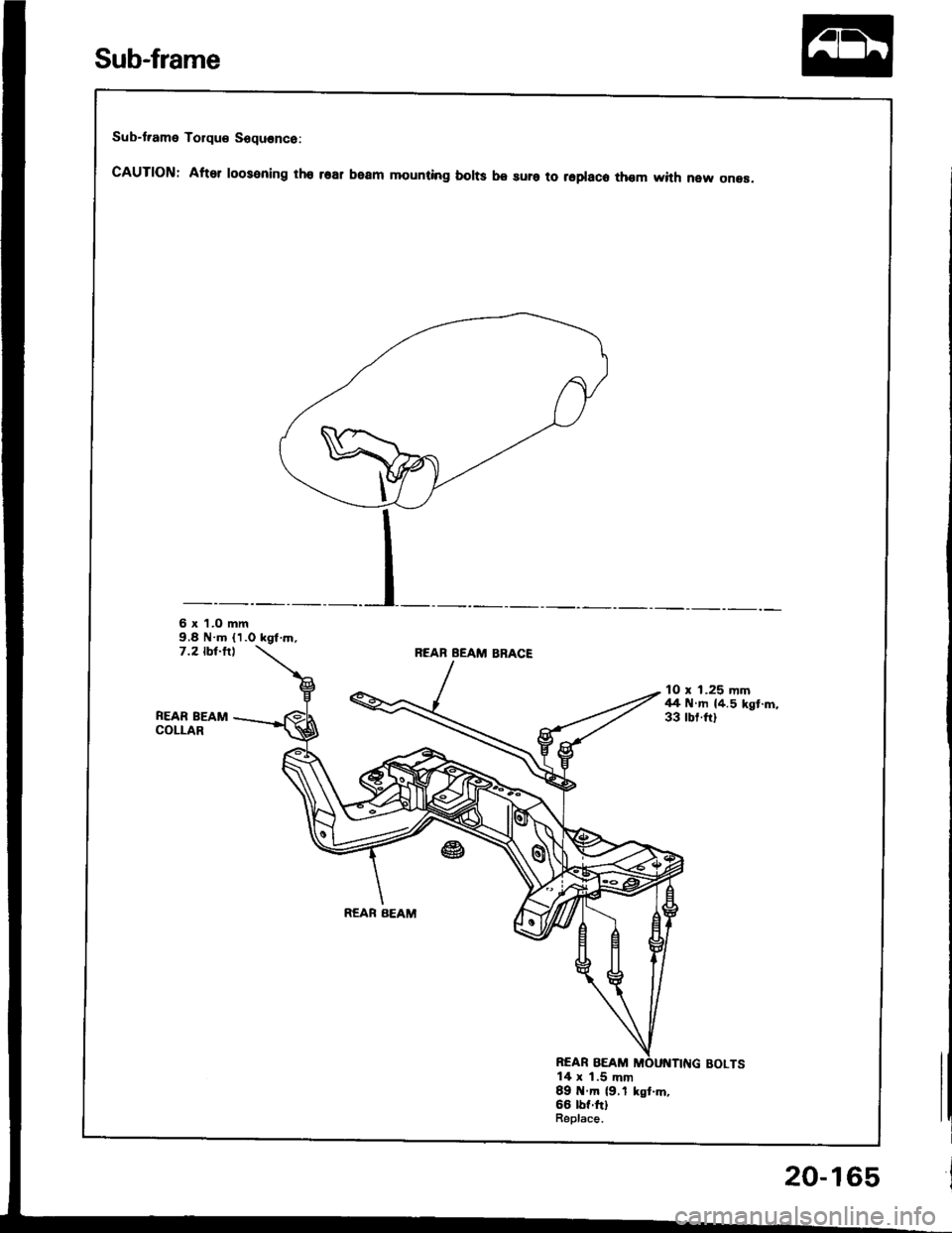
Sub-t.ame Torque Sequence:
cAUTloN: After roosening tho rsar beam mounting borts be sura to repraco thom with new onea.
6 x 'l.O mm9,8 N.m (1.0 kgt.rn,7.2 tbt-fllREAB BEAM BBACE
FEAR BEAMCOLLAR
10 x 1.25 mm44 N.m {4.5 kgt.m,33 rbr.ftl
REAR BEAM
REAR BEAM14 x 1.5 mm89 tt.m (9.1 kst.m,66 lbf.ftlBeplace.
Sub-frame
20-165
Page 1190 of 1413
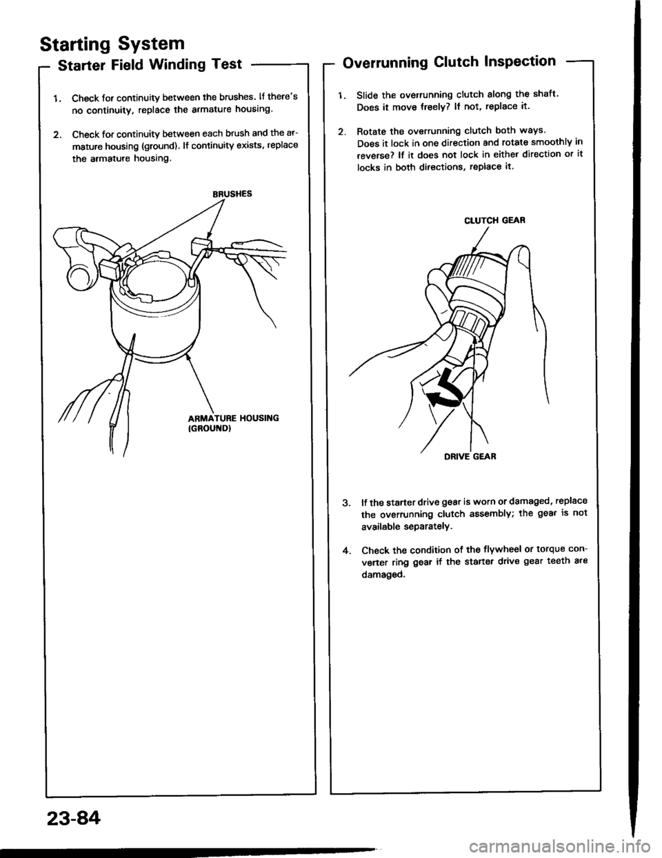
BRUSHES
Starting System
Starter Field Winding Test
1. Check for continuity between the brushes. lf there's
no continuity, replace the armature housing.
2. Check for continuity between each brush and the ar-
mature housing {ground) lf continuity exists, replace
the armatule housing.
Overrunning Clutch InsPection
Slide the overrunning clutch slong the shatt.
Does it move treely? ll not, replace it.
Rotate the overrunning clutch both ways.
Does it lock in one direction and rotate smoothly in
reverse? lf it does not lock in either direction or it
locks in both directions, replace it.
DRIVE G€AR
ll the starter drive gear is worn or damaged, replsce
the ovsrrunning clutch assembly; the gea. is not
available separately.
Check the condition of the flywheel or torque con-
verter ring gear if the starter drive gear teeth ale
damaged.
4.
23-8,4
CLUTCH GEAR
Page 1203 of 1413
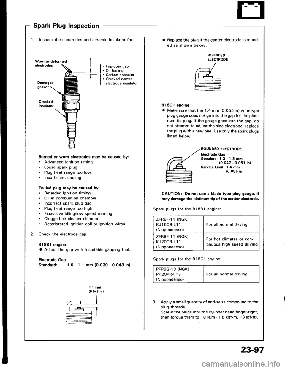
Spark Plug Inspection
1. Inspect the electrodes and ceramic insulator for:
. rmproper gap. Oil-touling. Carbon deposits. Cracked centerelectrode insulatorDamagedgask6t
Burned or worn electlodes may be caused by:. Advanced ignition timing. Loose spark plug. Plug heat range too low. Insufficient cooling
Fouled plug may be caused by:. Retarded ignition timing. Oil in combustion chamber. lncorrect spark plug gap. Plug heat range too high. txcessive idling/low speed running. Clogged air cleaner element. Deteriorated ignition coil or ignition wires
Check the electrode gap.
Bl88l engine:
a Adjust the gap with a suitable gapping tool.
Electrode Gap
Standard: 1.0-1.1 mm (O.O39-0.O43 in)
1.1 mm{0.0,$ in)
Replace the plug if the center electrode is round-
ed as shown below:
ROUNDEDELECTROOE
Bl8Cl engine:
a Make sure that the '1.4 mm (0.055 in) wire-typeplug gauge does not go into the gap for the plati-
num tip plug. lf the gauge goes into the gap, do
not attempt to adjust the side electrode; replace
the plug with a new one. Use only the spark plugs
listed below.
ROUNDEO ELECTRODE
Electrode GapStandard: 1 .2-'l .3 mm{0.047 -O.051 in)Service Limit: 1.4 mm{0.055 in)
CAUTION: Do not use a blade-type plug gaugs, it
may damage the platinum tip of the center olectrodo.
Spark plugs for the 81881 engine:
Spark plugs for the B'l8Cl engine:
PFR6G_13 (NGK) IPK2OPR-113 I For all normal driving
{Nippondenso)
3. Apply a small quantity ol anti-seize compound to the
plug threads.
Screw the plugs into the cylinder head iingef-tight,
then torque them to 18 N.m (1.8 kgf.m, 13lbf.ft).
ZFRsF-1 1 (NGK)
KJl6CR-11 1
(Nippondenso)
For all normal driving
ZFR6F-1 1 (NGK)
KJ2OCR-11 1(Nippondenso)
For hot climates or con-
tinuous high speed driving
23-97
Page 1214 of 1413
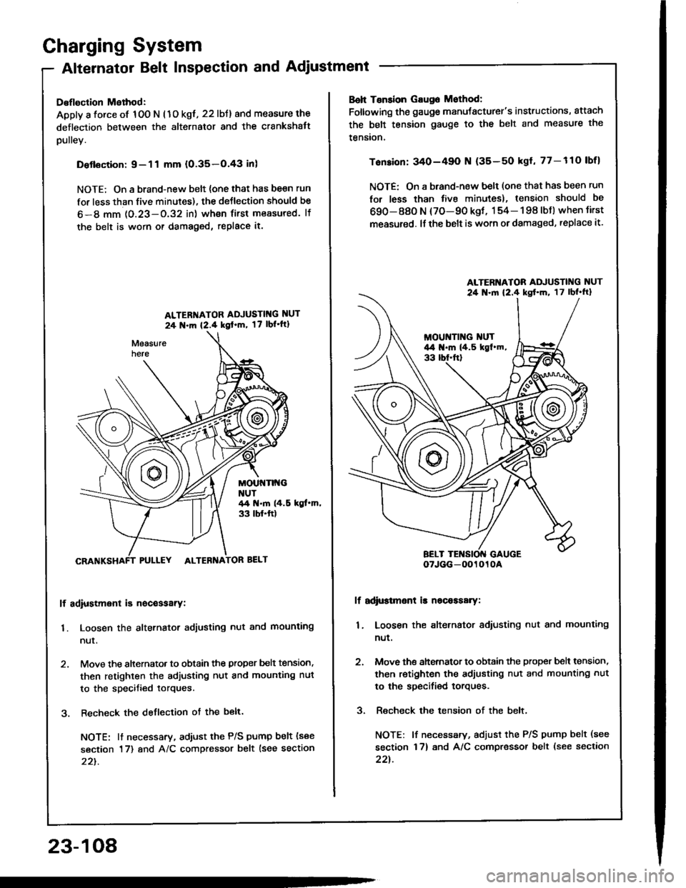
Charging System
Alternator Belt Inspection and Adjustment
Deflection Method:
Apply a force of 100 N (1o kgt, 22 lbJ) and measure the
deflection between the alternator and the crankshatt
pulley.
Detlsction:9-11 mm (0.35-O.43 inl
NOTE; On a brand-new belt {one that has be€n run
for less than five minutes), the deJlection should be
6-8 mm 1O.23-O.32 in) wh€n first measured. lf
the belt is worn or damaged, replace it.
ALTER'{ATOR ADJUSTIT{G NUT
24 N.m {2.4 kgl'm, 17 lbl'ft1
MOUt{Tlt{GNUT44 t{.m (4.5 kgt.m,33 tbf.ft)
PULLEY ALTEBNA
lf adiustment is nocessarY:
1. Loosen the alternator adjusting nut and mounting
nur.
2. Move the alternator to obtain the proper belt tension,
then retighten the adjusting nut and mounting nut
to the specified torques.
3. Recheck the deflection ot the belt.
NOTE: lt necessary, adiust the P/S pump belt (see
section 17) and A/C compressor belt lsee section
22t.
23-108
Boh Tsnsion Gaug6 Mothod:
Foltowing the gauge manuJacturer's instructions, attach
the belt tension gauge to the belt and measure the
tension.
Tension: 340-49O N (35-50 kgl, 77-110 lbfl
NOTE: On a brand-new belt (one that has been run
for less than tive minutes), tension should be
690-880 N (70-90 kgt, 154- 198 lbJ) when tirst
measured. lf the belt is worn or damaged, replace it.
lf adi$tmsnt is nscaasary:
1. Loosen the alternator adiusting nut and mounting
nut.
2. Move ths ahernator to obtain the proper bslt tension,
then retighten the adjusting nut and mounting nut
to the specified torques.
3. Recheck the tension of the belt,
NOTE: lf necessary, adjust the P/S pump belt (see
section 17) and A/C compressor belt (see section
22t.
ALTERI{ATOR ADJUSTING NUT
24 .ln 12.4 kst'm, 17lbl'ft}
oTJGG-0O1010A