Ax belt HONDA INTEGRA 1994 4.G Repair Manual
[x] Cancel search | Manufacturer: HONDA, Model Year: 1994, Model line: INTEGRA, Model: HONDA INTEGRA 1994 4.GPages: 1413, PDF Size: 37.94 MB
Page 987 of 1413
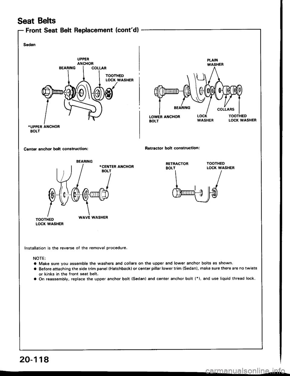
Front Seat Belt Replacement (cont'd)
Seat Belts
Sodan
.UPPER ANCHORBOLT
Canter anchor bolt consttuction:Rotractor bolt conslruction:
WAVE WASHER
Installation is the reverse ot the removal procedure.
NOTE:
a Make sure you assemble the washers and collars on the upper and lower anchor bolts as shown.
a Before attaching the side trim panel (Hatchbackl or center pillar lower trim (Sedan l. make sure the.e are no twists
or kinks in the front seat belt.
a On reassembly, replace the upper anchor bolt {Sedanl and center anchor bolt (*), and use liquid thread lock.
20-118
BEARING
Page 988 of 1413
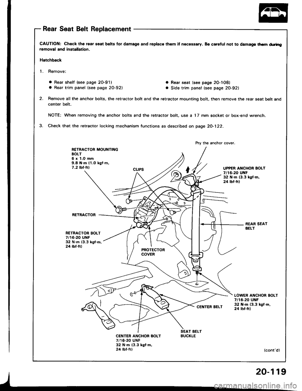
Rear Seat Belt Replacement
CAUTION: Check lhs roar saat bslts tor damago and ioplaca them it necassary. 86 careful not to damago thcm d.rheromoval and imtallation.
Hatchback
1. Remove:
o Rear shelf {see page 20-911
a Rear trim panel (see page 20-921
. R€ar seat (see page 20-1081
a Side trim panel (see page 20-921
Remove all the anchor bolts, the retractor bolt and the retractor mounting bolt, then remove the rear seat belt and
center belt.
NOTE: When removing the ancho. bolts and the retractor bolt, use a 17 mm socket or box-end wrench.
Check that the retractor locking mechanism functions as described on page 2O-122.
RETRACTOR MOUNTINGBOLT6xl.Omm9.8 N.m {'l.O kgf.m,7 .2 tbt.ttlUPPER ANCHOR BOLT7/16-20 Ul{F32 N.m (3.3 kgt.m,24 tbt.ft)
RETRACTOB
NETRACTOR BOLT7/16-20 UNF32 N.m (3.3 kgl.m,24 tbt.fr)
REAR SEATAELT
LOWER ANCHOR BOLT7 t16-20 UNF32 N'm 13.3 kgf.m,24 tbt.ftl
CENTER ANCHOR BOLT7/16-20 UNF32 N.m {3.3 kgl m,24 lbf.ft)
Pry the anchor cover.
BUCKLE
(cont'd)
Page 989 of 1413
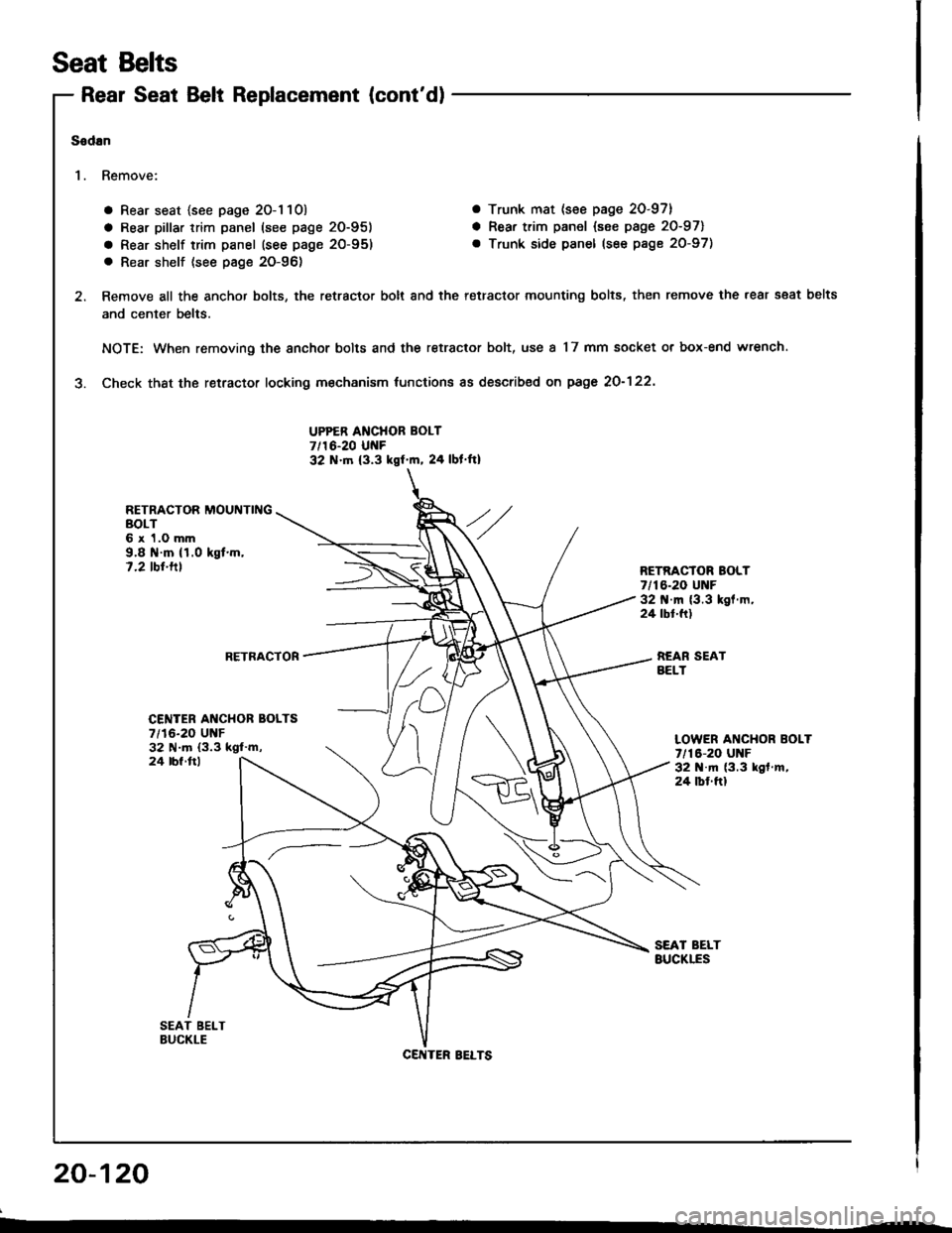
Rear Seat Belt Replacement (cont'd)
a Rear seat {see page 20-1 10) a Trunk mat (see page 20-97}
a Rear pillar trim panel (see page 20-951 a Rear trim panel {see page 20-971
a Rear shelf trim panel (see page 20-95) . Trunk side panel (see page 20-97)
. Rear shelf (see pag€ 20-96)
Remove all the anchor bolts, the retractor bolt and the retractor mounting bolts, then remove the rear s€at belts
and center belts.
NOTE: When removing the anchor bolts and the retractor bolt, use a 17 mm socket or box-end wrench.
Check thst the retractor locking m€chanism tunctions as described on page 2O-122'
UPPER ANCHOR BOLT7/16-20 UNF32 N.tn (3.3 kgf'm, 24 lbl ft)
RETRACTOR MOUNTINGBOLT6 x 1.0 mm9.8 il.m (1.0 kgt.m,7.2 tbt.tllRETRACTOR BOLT7/16-20 UNF32 .m (3.3 kgl.m,24 tbt.ft)
RETRACTORREAR SEATBELT
Seat Belts
Sodan
'I . Remove:
20-120
CENTER AI{CHOR BOLTS7/16-20 UNF32 N.m (3.3 ksl'm,LOWER ANCHOR BOLT7/16-20 UNF32 N.m (3.3 kgf .m,
24 tbf.ftl
24 lbl ftl
CENTER BELTS
Page 990 of 1413
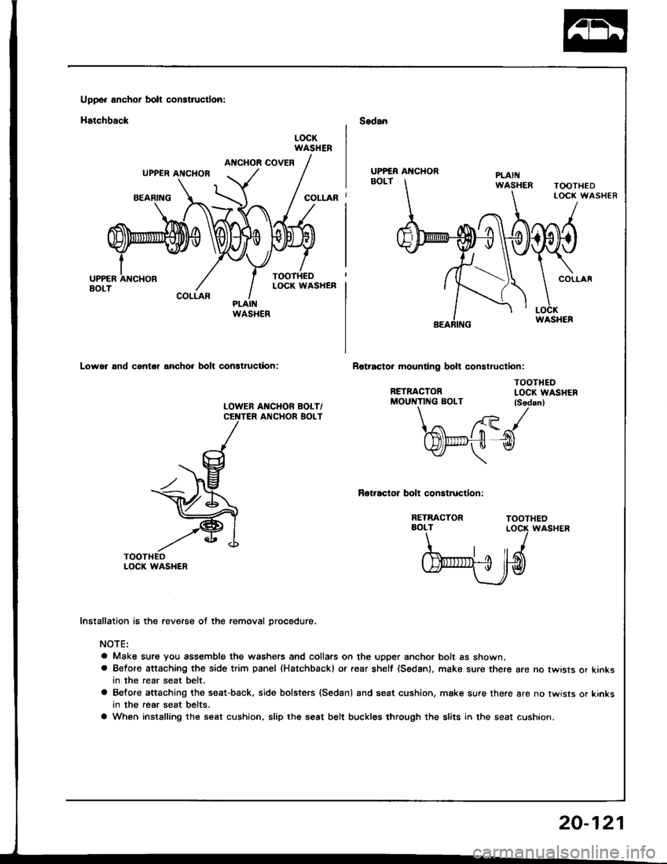
Uppo. anchor bolt construction:
Hatchback
ANCHOR COVERUPPER ANCHOB
BEARING
COLLAR
Lower and cantol ancho. bolt conatluction:
LOWEB AI{CHOR BOLT/ANCHOR BOLT
Sedan
Rotracto. mounting bolt construclion:
RETRACTOR
LOCKWASHER
COLLAR
TOOTHEDLOCK WASHEN
TOOTHEDLOCK WASHER
TOOTHEDLOCK WASHER
TOOTHEOLOCK WASHER
UPPER AI{CHOR
WASHER
MOUNTING BOLT {Sedanl\/ /{- tr- J
l$t".,-,fu l-n(tYlf- u tY
\
Rotractor bolt construction:
RETRACTORAOLT
b'ryd
Installation is the reverse of the removal procedure.
NOTE:
a Make sure you assemble the washers and collars on the upper anchor bolt as shown.a Before attaching the side trim panel (Hatchbackl or rear shelf (Sedan), make sure there are no twists or kinksin the rear seat belt.
a Before attaching the seat-back, side bolsters {Sedan) and seat cushion, make sure there are no twisls or kinksin the rear seat belts.
a When instslling the seat cushion, slip the seat belt buckles through the slits in the seat cushion.
20-121
Page 991 of 1413
Seat Belts
lnspection
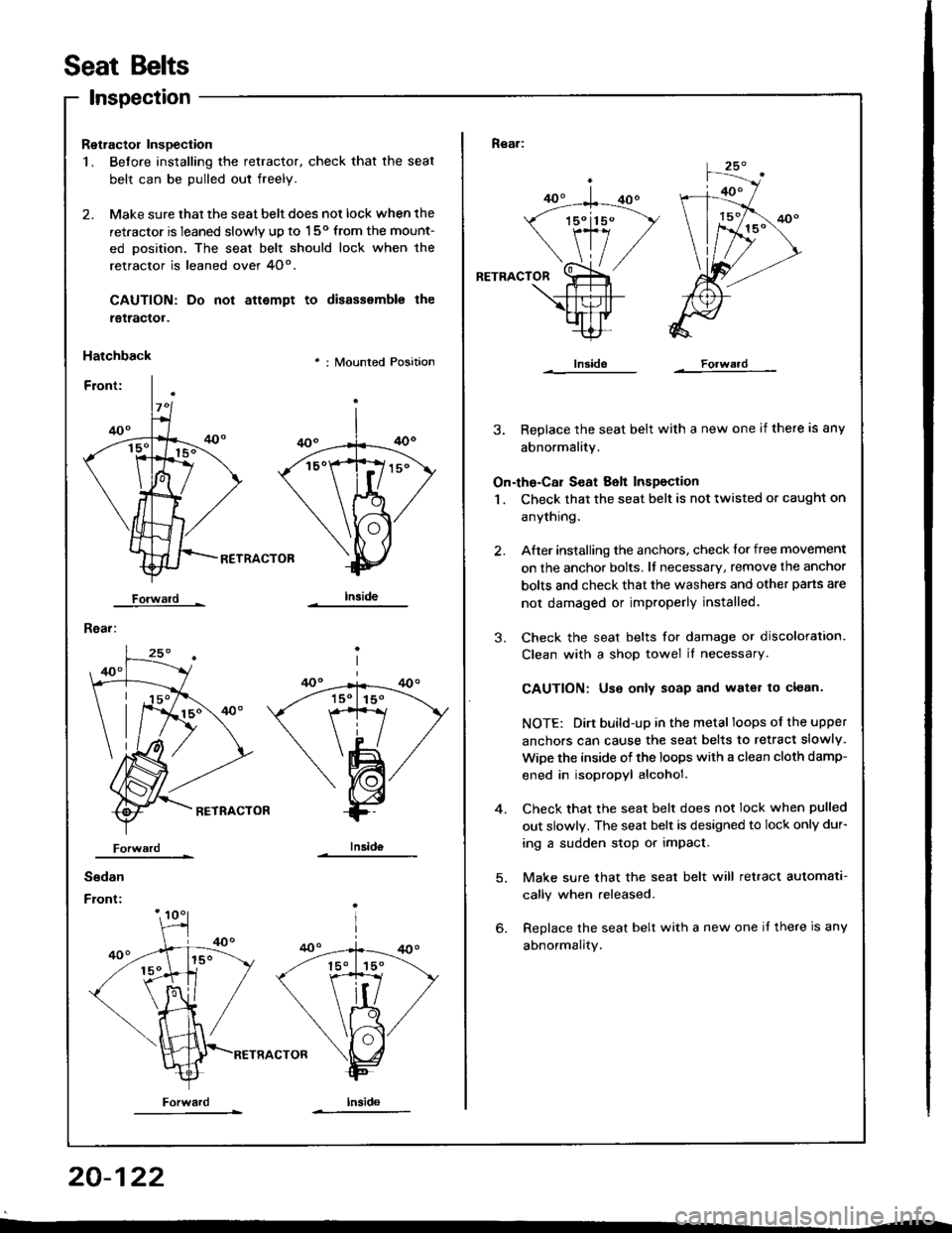
Retractol InsDection
1. Before installing the retractor, check that the seat
belt can be pulled out freely.
2. Make sure that the seat belt does not lock when the
retractor is leaned slowly up to 150 from the mount-
ed oosition. The seal belt should lock when the
retractor is leaned over 4O".
CAUTION: Do
tgtractol.
Hatchback
Forwald -
Rear:
not attempt to disassemble the
' : Mounted Position
RETRACTOB
Iniid6
Sedan
Front:
Forwardlnsido
Forward
Rear:
RETRACTOR
3. Replace the seat belt with a new one if there is any
abnormality.
On-the-Cal S€at Belt Inspection
1 . Check that the seat belt is not twisted or caught on
anythrng.
After installing the anchors, check lor free movement
on the anchor bolts. lf necessary, remove the anchor
bolts and check that the washers and other pans are
not damaged or improperly installed.
Check the seat belts for damage or discoloration.
Clean with a shop towel iI necessary.
CAUTION: Use only soap and water to clean.
NOTE: Dirt build-up in the metal loops of the upper
anchors can cause the seat belts to retract slowly.
WiDe the inside of the loops with a clean cloth damp-
ened in isopropyl alcohol.
Check that the seat belt does not lock when pulled
out slowly. The seat belt is designed to lock only dur-
ing a sudden stop or impact.
Make sure that the seat belt will retract automata-
cally when released.
Replace the seat belt with a new one it there is any
abnormality.
2.
3.
4.
20-122
Page 993 of 1413
Garpet
Replacement
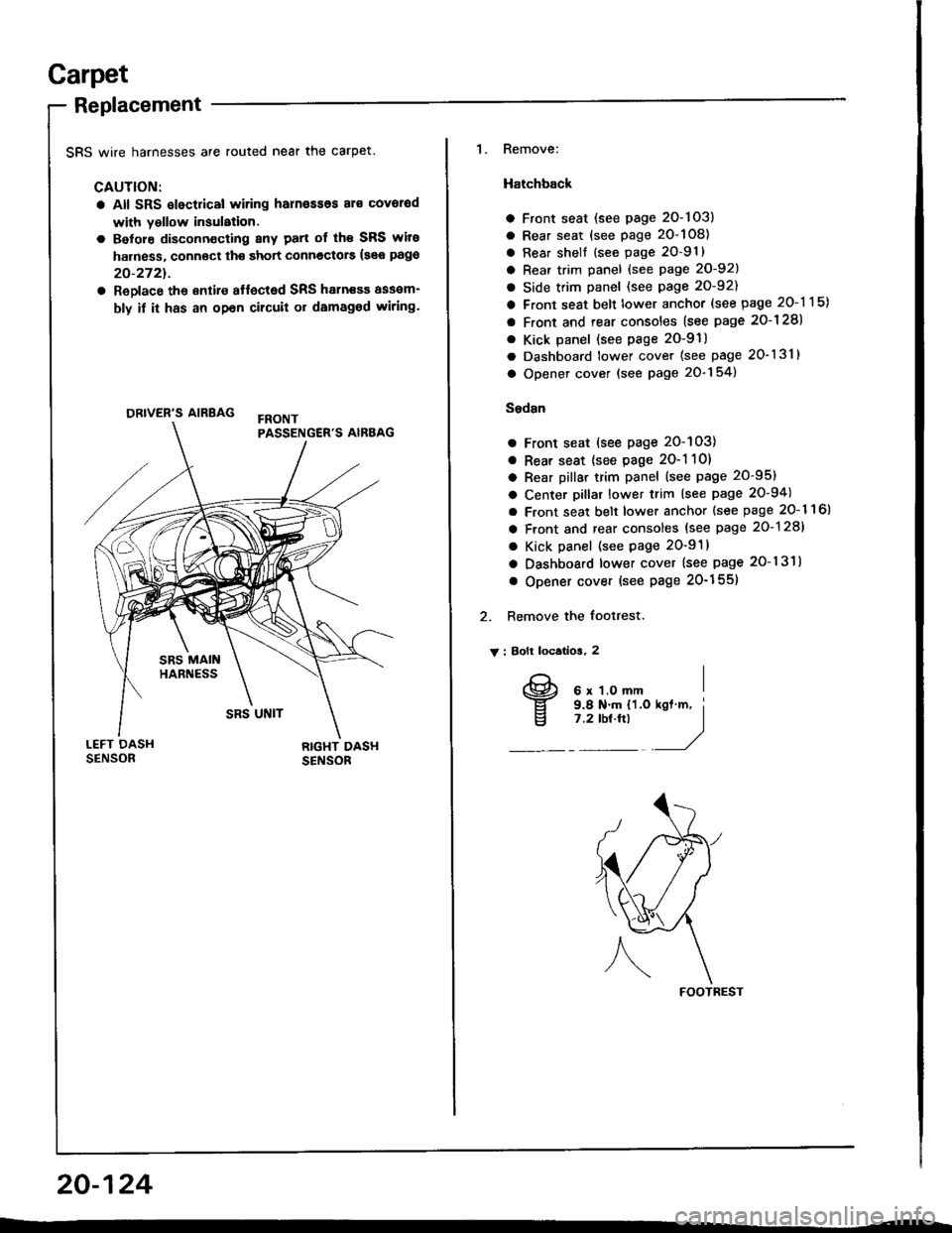
SRS wire harnesses are routed near the carpet.
CAUTION:
a All SRS slectrical wiring harn€ssos al€ covorod
with yollow insulation.
a Belore disconn€cting 8ny patt of th€ SRS wite
harness, connoct th€ short connectors {see pago
20-2721.
a ReDlace the €ntire affected SRS haln€sa assam-
bly if it has an opan cilcuit or damaged wiring.
ORIVER'S AIRBAG
1. Remove:
Hatchback
a Front seat (see page 2O-103)
a Rear seat (see page 20-108)
a Rear shell {see page 2O-91}
a Rear trim panel {see Page 20-921
a Side trim panel (see page 20-92)
a Front seat belt lower anchor (see page 20-115)
a Front and rear consoles (see page 2o-128)
. Kick panel (see page 2O-91)
a Dashboard lower cover (see page 20-131)
a Opener cover (see page 20-154)
Sedsn
a Front seat (see page 20-103)
a Rear seat {see page 2O-1 10)
a Rear pillar trim panel (see page 20-95)
a Center pillar lower trim (see page 20-94)
a Front seat belt lower anchor {see page 20- 1 1 6l
a Front and rear consoles (see page 20-128)
a Kick panel (see page 20-91)
a Dashboard lower cover (see page 20-131)
o Opener cover (see Page 20-155)
2. Remove the footrest.
V : Bolt locatios, 2
FOOTREST
20-124
I
v
6 x 1.O mm9.8 N.m {'l.o7 .2 tbt.ftl
Page 1016 of 1413
8.
o.
7.
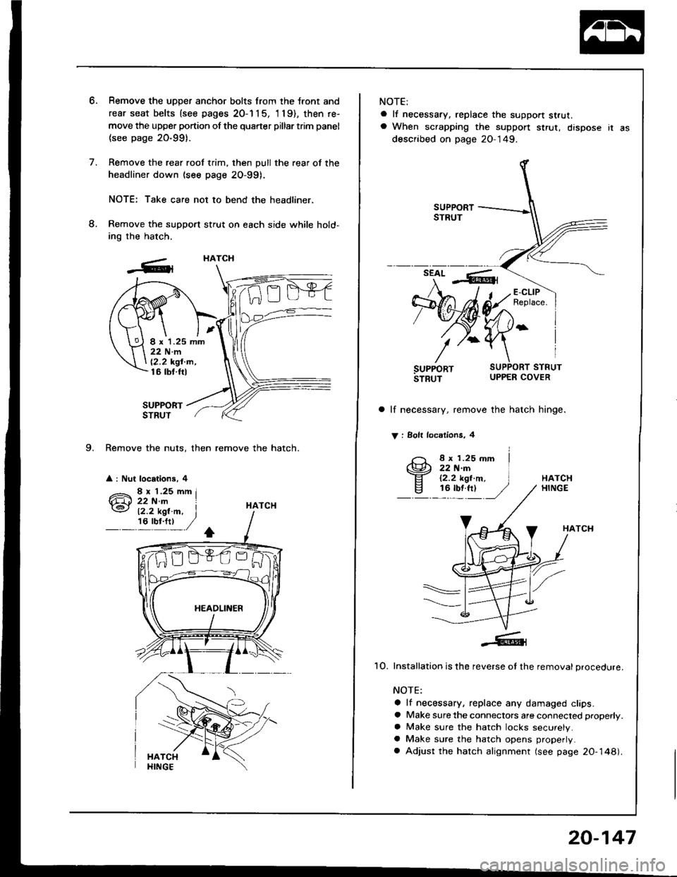
9. Remove the nuts, then remove the hatch.
a : Nut locations, 4
Remove the uDDer anchor bolts from the tront and
rear seat belts {see pages 20-1 1 5, 'l 19), then re-
move the upper portion of the quarter pillar trim panel
(see page 20-991.
Remove the rear roof trim, then pull the rear of the
headliner down (see page 2O-99).
NOTE: Take care not to bend the headliner,
Remove the support stfut on each side while hold-
ing the hatch.
SUPPORTSTRUT
HATCH
HATCH
I x 1.25 mm22Nm
12,2 kgt'm,16 tbt.ftl
12.2 kgl.m, I,6'y!:t ,/
NOTE:
a lf necessary, replace the support strut.a When scrapping the suppon $rut, dispose ir as
described on page 20-149.
a lf necessary, remove the hatch hinge.
V : Solt locdlions, 4
8 x 1.25 mm22 N.rn12.2 kgt.m,16 tbf.ft)HATCHHINGE
HATCH
1O. Installation is the reverse ot the removal procedure.
NOTE:
a lf necessary, replace any damaged clips.a Make sure the connectors are connected properly.
a Make sure the hatch locks securely.a Make sure the hatch opens properly.
a Adjust the hatch alignment (see page 20-148).
20-147
Page 1069 of 1413
Air Conditioning
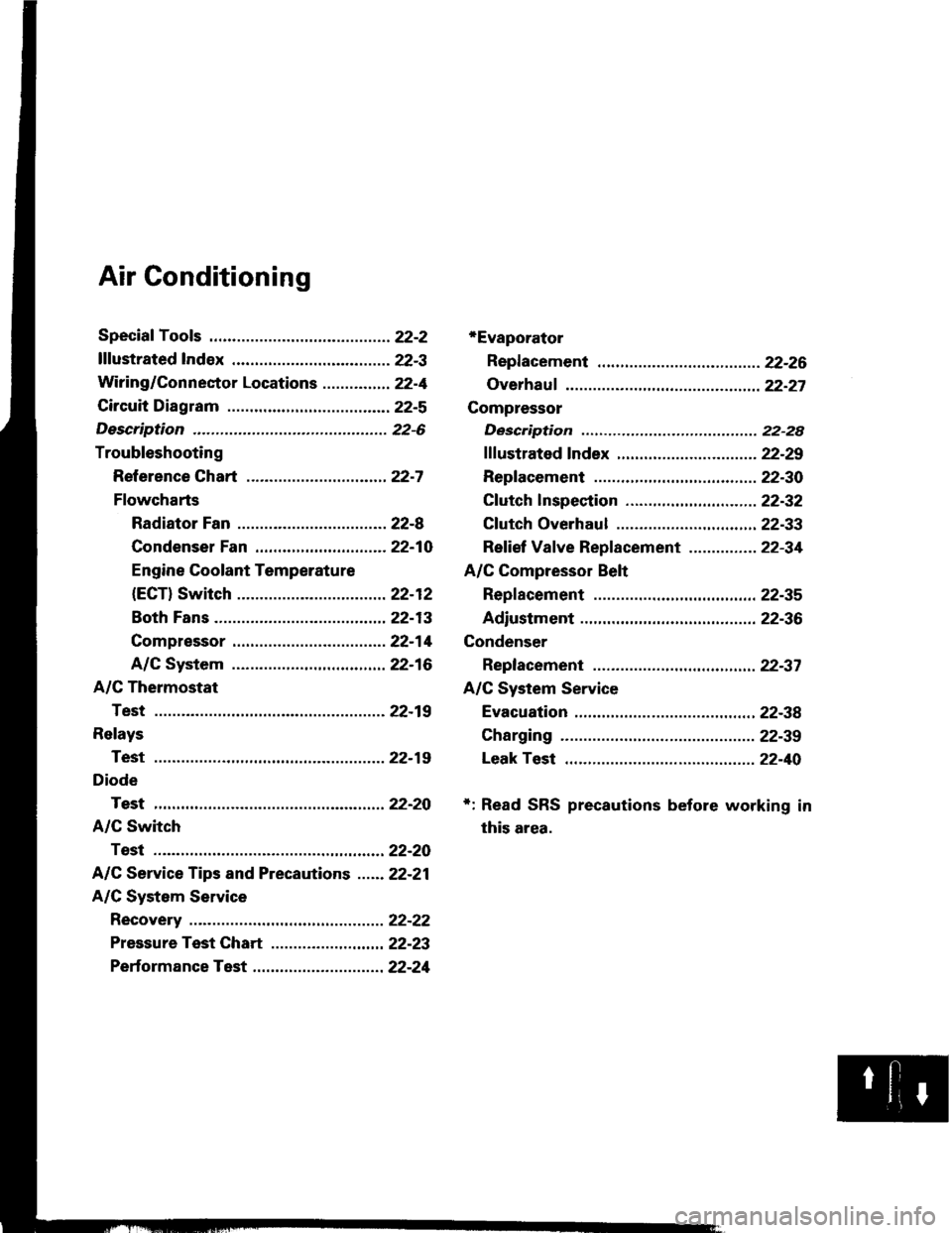
*Evaporator
Repf acement .........22-26
Overhauf ................ 22-27
Compressor
Description ............ 22-28
fffustrated fndex ............................... 22-29
Replacement .........22-30
Cf utch lnspection ....................... ...... 22-32
Cf utch Overhaul ............................... 22-33
Ref ief Vaf ve Replacement ............... 22-34
A/C Compressor Belt
Repf acement .........22-35
Adiustment ............22-36
Condenser
Replacement ......... 22-37
A/C System Service
Evacuation ....,.......,22-38
Charging ................ 22-39
Leak Test ...............22-40
+: Read SRS precautions before working in
this area.
Page 1070 of 1413
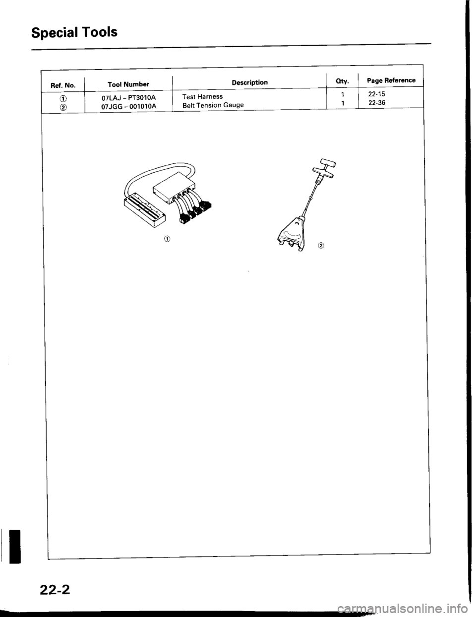
Special Tools
Ref. No. I Tool Numbel
Test Harness
Belt Tension GaugeOTLAJ - PT3O1OA
07JGG - 001010A
I
22-2
Page 1101 of 1413
A/C Compressor Belt
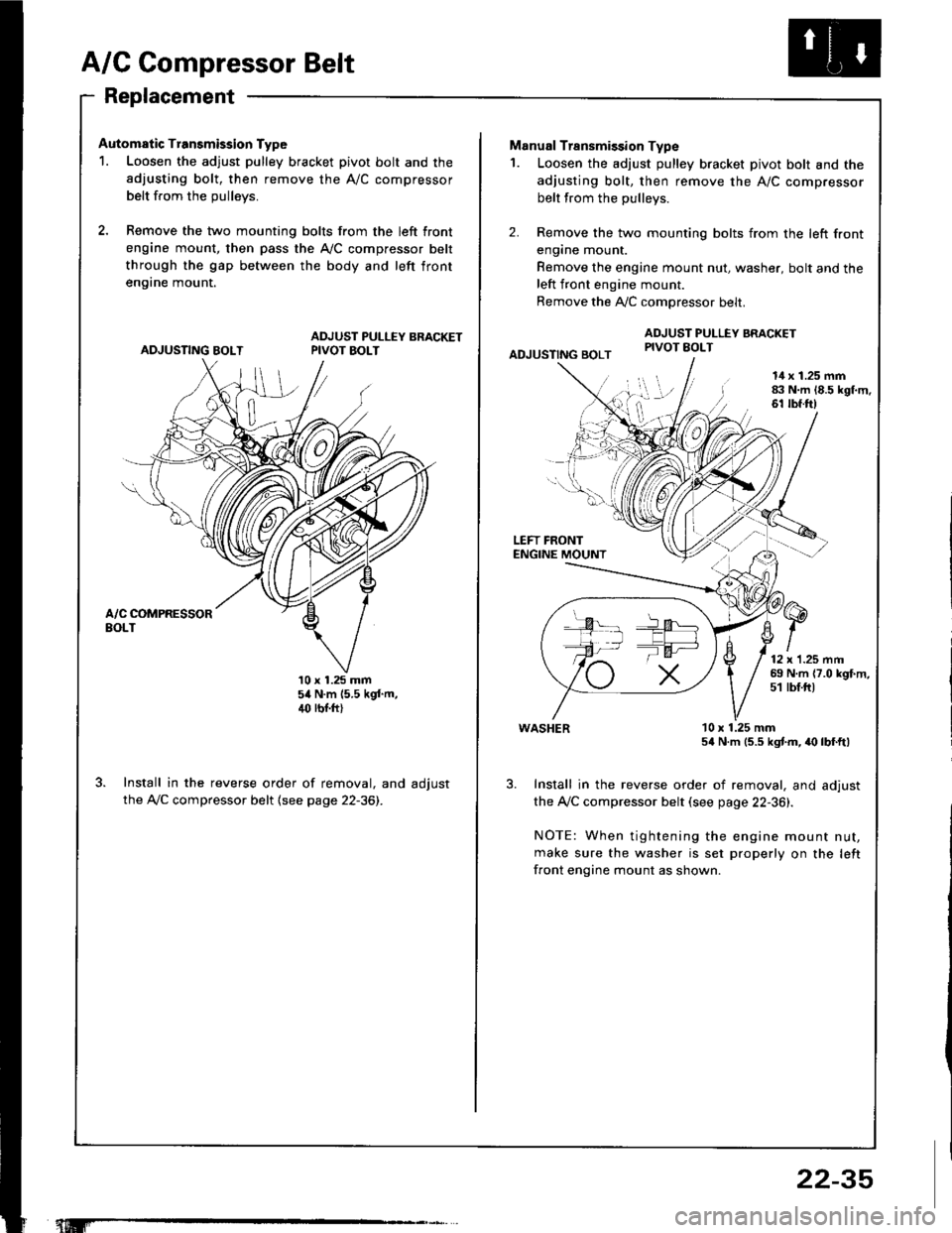
Replacement
Automatic Transmission Type
1. Loosen the adjust pulley bracket pivot bolt and the
adjusting bolt, then remove the A/C compressor
belt from the oullevs.
2, Remove the two mounting bolts from the left front
engine mount, then pass the A,/C compressor belt
through the gap between the body and left front
en9rne mount.
ADJUSTING BOLTADJUST PULLEY BRACKETPIVOT BOLT
10 x 1.25 mm54 N.m (5.5 kgf.m,4(' rbr.ft)
Install in the reverse order of removal, and adjust
the A,/C compressor belt (see page 22-36).
"t.M'
22-35
-la ar-
Manual Transmission Type
1. Loosen the adjust pulley bracket pivot bolt and the
adjusting bolt, then remove the A/C compressor
belt from the pullevs.
2. Remove the two mounting bolts from the left front
engane mount.
Remove the engine mount nut, washer, bolt and theleft front engine mount.
Remove the A,./C comoressor belt.
ADJUSTING BOLT
ADJUST PULLEY BRACKETPIVOT EOLT
l!l',
I
14 x 1.25 mm83 N.m 18.5 kgl.m.61 tbf.ft)
LEFT FRONTENGINE MOUNT
12 x'1.25 mm69 N.m {7.0 kgf.m,51 tbf.ftt
WASHER
Install in the reverse order of removal, and adjust
the Ay'C compressor belt (see page 22-36).
NOTE: When tightening the engine mount nut,
make sure the washer is set properly on the left
front engine mount as shown.
10 x 1.25 mm54 N.m (5.5 kgtm, irc lbf.ft)