Ax belt HONDA INTEGRA 1994 4.G Manual PDF
[x] Cancel search | Manufacturer: HONDA, Model Year: 1994, Model line: INTEGRA, Model: HONDA INTEGRA 1994 4.GPages: 1413, PDF Size: 37.94 MB
Page 1102 of 1413
A/C Compressor Belt
Adjustment
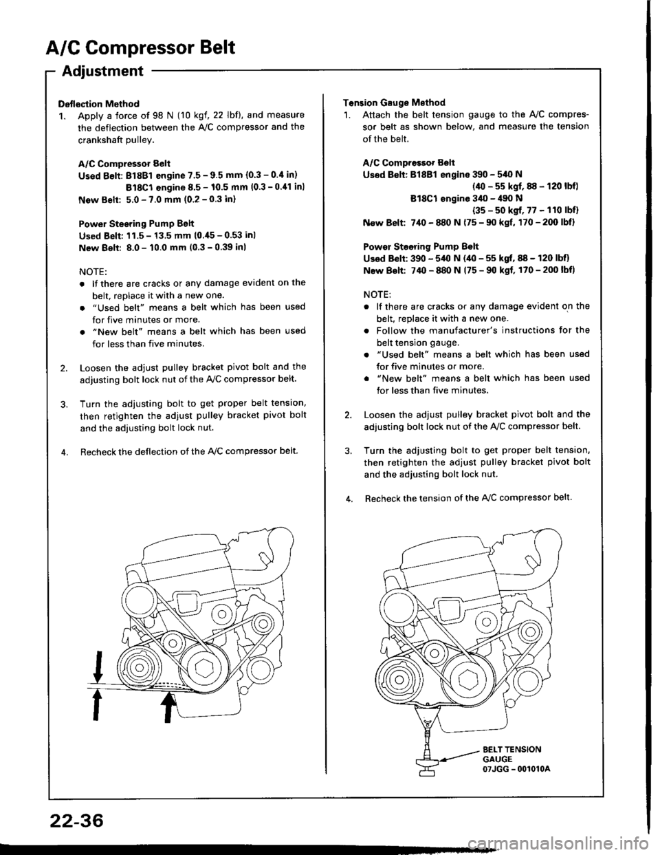
Dstlsqtion Method
1. Apply a force of 98 N (10 kgf, 22 lbf), and measure
the deflection between the A,/C compressor and the
crankshaft Dullev.
A/C Compressor Belt
Us€d Eelt: 81881 engine 7.5 - 9.5 mm (0.3 - 0.4 in)
Bl8Cl engine 8.5 - 10.5 mm (0.3 -0.11 inl
New Belt: 5.0 - 7.0 mm (0.2 - 0.3 inl
Power Stesring Pump Belt
Used Beli: 'l1.5 - 13.5 mm (0.,[5 - 0.53 inl
New 8€lt: 8.0 - 10.0 mm (0 3 - 0.39 inl
NOTE:
. lf there are cracks or any damage evident on the
belt, replace it with a new one.
. "Used belt" means a belt which has been used
for five minutes or more.
. "New belt" means a belt which has been used
for less than five minutes.
2. Loosen the adjust pulley bracket pivot bolt and the
adjusting bolt lock nut of the Ay'C compressor belt.
3. Turn the adiusting bolt to get proper belt tension,
then retighten the adjust pulley bracket pivot bolt
and the adjusting bolt lock nut.
4. Recheck the deflection of the lvc compressor belt
22-36
Tonsion Gauge Method
1. Attach the belt tension gauge to the Ay'C compres-
sor belt as shown below, and measure the tension
of the belt.
A/C Compressot Belt
Used 8€lt: Bl8Bl engine 390 - 540 N
(40 - s5 kgf, 88 - 120 lbfl
Bl8Cl ongine 3il0 - il90 N
(35 - s0 kgf, 77 - 110 lbfl
N€w Belt 7,10 - 880 N {75 - 90 kgf, 170-200lbl}
Powor Steoring Pump Belt
Used Belt: 390 - 5,{l N (40 - 55 kgf, 88 - 120 lbll
N6w Bolt: 74O - 880 N 175 - 90 kgf, 170-200lbt)
NOTE:
. lf there are cracks or any damage evident on the
belt, replace it with a new one.
. Follow the manufacturer's instructions for the
belt tension gauge.
. "Used belt" means a belt which has been used
for five minutes or more.
. "New belt" means a belt which has been used
tor less than five minutes,
2. Loosen the adjust pulley bracket pivot bolt and the
adjusting bolt lock nut of the AVC compressor belt.
3, Turn the adjusting bolt to get proper belt tension,
then retighten the adjust pulley bracket pivot bolt
and the adjusting bolt lock nut.
4. Recheck the tension of the A{/C compressor belt.
Page 1107 of 1413

Electrical
Special Tools
Troubleshooting
Tips and Precautions ................................ 23-3Five-stop Tloubleshooting ..............,...-..-... Z3-sSchematic Symbols ................................_. 23-6wire Color Cod€s ..................................... 23-6Relay and Control Unit Locations
Engine Compartment .........,............ ... --. 23-7Dsshboard and Door ..,,......................... 23-gDashboard and Floor ............................. 23-t OOuaner Panel .....-.....23-12Connector ldentification and WireHarness Routing ........ 23-i 3
Index to Circuits and Systems
Airbag ............... ...-..-... 2g-26sAir Conditioning ....,.. Section 2lAltelnator ......_.............. 23-99Anti-lock Brake Systsm (ABS) Section 19Automatic Transmission Section 14Battery .............. .......... 23-66Chafging System ........... 23-98rCigalstte Lighter .....................-...-......-..-.. Z3-2O4Cfock ................. ..........23-197rcruise Controf .......--..-... 23-242Distributor .................... 23-87Fan Controls ................. 23-1ogFuel and Emissions ... Section 1i*Fuses
Under-dash Fuse/Relay Box ................... 23-48Undor-hood ABS Fuse/Retay Box ............ 23-51Under-hood Fuse/Relay Box,.................. 23-52rGauges
Engine Coolant Temperature {ECT)Gauge ................ ..23-126Fuef cauge ............... 2g-123'Gauge Assembly ....--.23-113Speedometer .....-...,,. 23-114Tachometer .....,.....-.. 23-114Ground Distribution ........ 23-60Heater ,,,........,.... ..... Section 2lrHorn ................. ........... 23-199*fgnition Switch ............. 23-70fgnition Syst6m .......-..-.. 23-A7lgnition Timing .............. 23-89Indicator Lights"A/T Gear Position .............. ................... 23-1 32B1ak6 System ...,..,..-.23-127Engine Oil Pressura .............................. _ 23-1 51Low Fuel ............ ......23-125Malfunction Indicator Lamp {MlL} ...,,. Section I l
tfnteglated Control Unit ...29-144*lnterlock System ...................................... 23-1 3gLights, Exteriol
Back-up Lights ........... 23-179Brake Lights .............. 23-t8ltDaytime Running Lights {Csnada} ........... 23-156Front Palking Lights ............................. 23-1 65Flont Side Marker Lights ....................... 23-165Front Turn Signal Lights ........................ 23-1 65*Hazard Warning Lights .........................- 2g-1A4Headlights ................. 23-t6tLicense Plate Lights .............................. 23-1 69Taillights(Harchback) .......... 23-166
{Sedan) .............. .. 23-167Lights. Inteliol
Cargo Area Light {Hatchback) ...... -.. -.. -... 23-177Ceifing Light ........-..-.23-175
Dash Lights Blightness Controt .............. 23-t70Glove Box Lighr ................................... 23-1 69Spotfighr ............ ....-.23-174Trunk Light (Sedanl ............... .............. - 23.-177*Lighting Sysrem .......-.-... 23-152:Moonroof ,,.,.......,..,,,,,.-.23-211PGM-FI Systom ........ S€crion 11Power Distribution .,.-..--..23-54Power Door Locks .............,,..................... 23-233Power Mirors ..,..,....-...- 23-216Power Relays ...........,..... 23-68Power Windows ............ 29-222*Rear Window Defogger ........,... ..........,..... - 23-20,6Reminder Systems
Key-in Remindel System ....,.............,.... 23-1 50Lights-on Reminder System ................... 23-l 5f*Maintenance Reminder system ..,,.... -.. - -. 23-.1 2gSeat Belt Reminder System ..................- 23-125*Side Markel/Turn Signal/Hazard
Ffasher System .,..,..-.23.-1A4Spark Pfugs .........-...-..... 23-97Starting System ....,,.....-. 23-73*Stereo Sound System ...,.......................,,.. 23-l gg
Supplemental Restraint System {SRS} ......... 23-265Vehicfe Speed Sensor {VSS) .............--..-.... 23-122*Wiper/Washer Systom ...............--.........-..- Zg-254
rRead SRS pi€cautions on Page 23-271 betore workingin these areas.
-+
Page 1108 of 1413
Special Tools
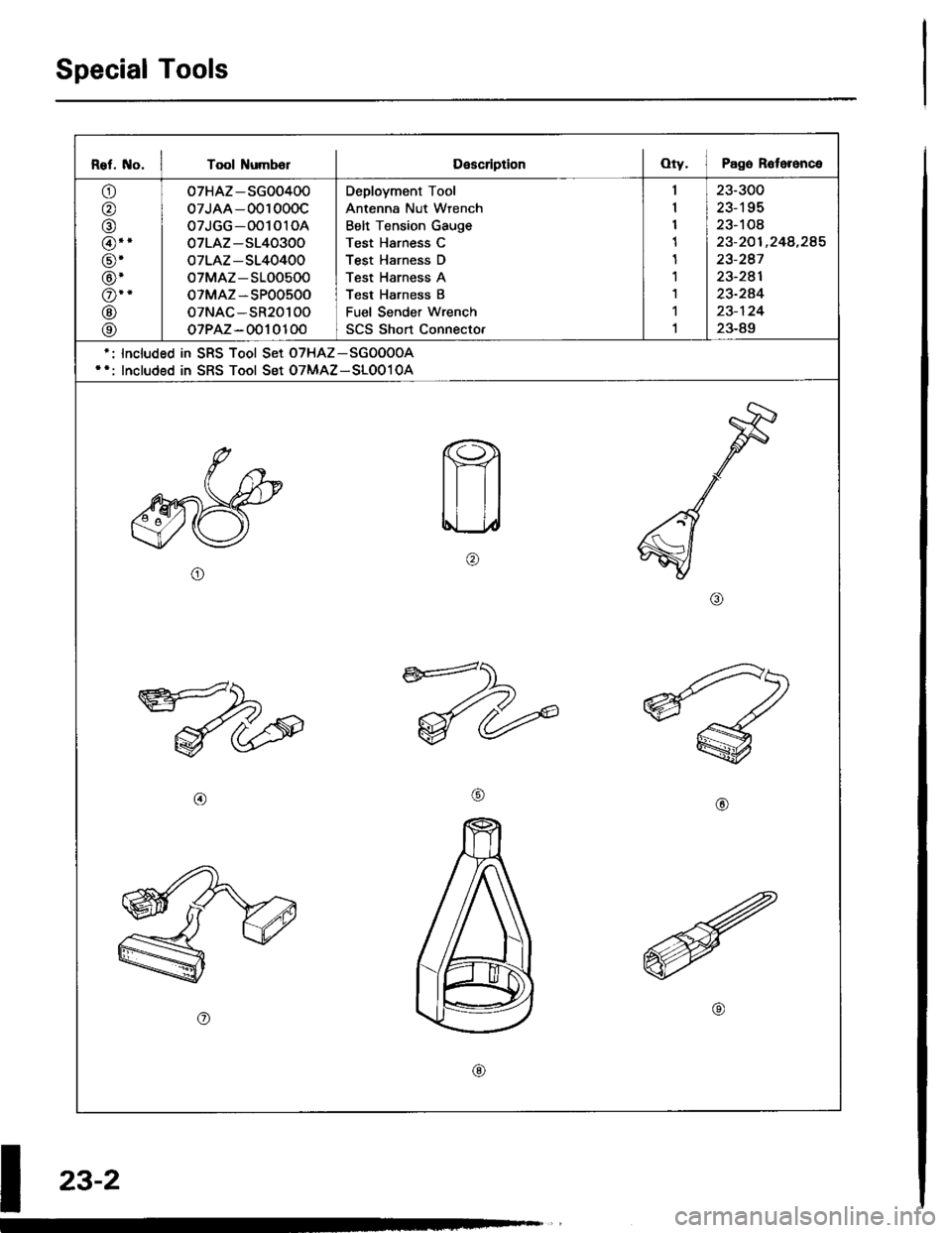
Rel. No. I Tool NumbolDescriptionOty. I Pago R6toronce
o
o
@
@.'
@'
@'
o--
@
@
07HAZ-SG00400
07JAA-001000c
07JGG-001010A
07LAZ-S140300
oTLAZ-S140400
oTMAZ-S100500
oTMAZ-SP00500
oTNAC-SR20100
oTPAZ-0010100
Deployment Tool
Antenna Nut Wrench
Belt Tension Gauge
Test Harness C
Test Harness D
Test Harness A
Test Harness B
Fuel Sender wrench
SCS Short Connecto.
23-300
23-195
23-108
23-201 ,248,285
23-247
23-241
23-244
23-124
23-89
lncluded in SRS Tool Set oTHAz-SGoOooA
Included in SRS Tool Set OTMAZ-SLOo10A
o
@@
o
@
I
z3-2
Page 1109 of 1413
Troubleshooting
Tips and Precautions
Before Troubloshooting
a Check applicable fuses in the appropriate fuse/relay
DOX.
a Check the battery for damage, state of charge, and
clean and tight connections.a Check the alternator belt tension.
CAUTION:
a Do not quick-charg€ a battery unless the batteryground cabla has be€n disconnoctsd. oth€rwisoyou will damage the alternator diodss.a Do not att6mpt to crank the engine with the bat-tery ground cable loosely connectsd or you will se-vorsly damag€ tho widng.
a The original radio has a codod thatt plotection ci.-cuit. Be sul€ to got tho customor's code numbet
before- disconnecting th€ battery.- lomoving tho No. 32 (7.5 Al tuso f.om the
under-hood tuse/lelay box.- removing tho radio.
Aflor s€lvic€. reconn€ct powet to tho radio and
turn it on. Whon the word "CODE" is displayed,
€nt€l the customer'E s-digit codo to .astore ladio
operation.
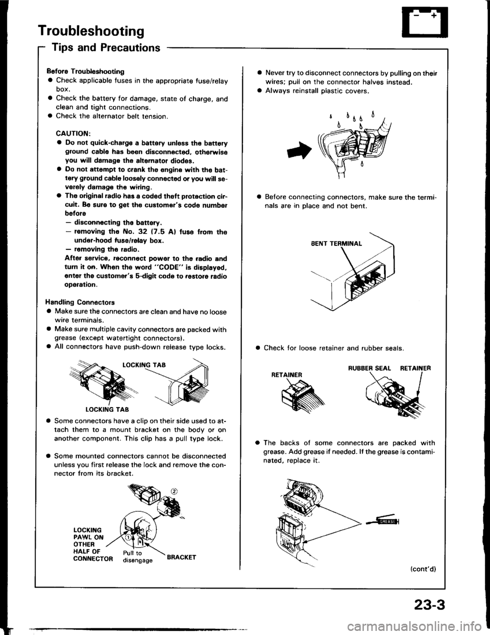
Handling Connectors
a Make sure the connectors are clean and have no loose
wire terminals.
a Make sure multiple cavity connectots are packed withgrease (except watertight connectors).a All connectors have push-down release type locks.
LOCKII{G TAA
LOCKING TAB
a Some connectors have a clio on their side used to at-
tach them to a mount bracket on the body or on
another component. This clip has a pull type lock.
a Some mounted connectors cannot be disconnected
unless you first release the lock and remove the con-
nector from its bracket.
LOCKINGPAWL ONOTHERHALF OFPull toorsengageCONNECTORBRACKET
23-3
a Never try to disconnect connectors by pulling on thei.
wires; pull on the connector halves instead.
a Always reinstall plastic covers.
Belore connecting connectors, make sure the lermi-
nals are in Dlace and not bent.
a Check tor loose retainer and rubber seals.
RETAINER
a The backs of some connectors are oacked with
grease. Add grease if needed. It the grease is contami-
nated, reDlace it.
(cont'd)
Page 1134 of 1413
Connector ldentification and Wire Harness Routing
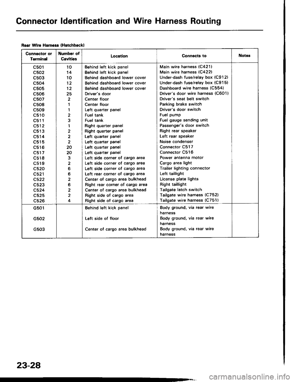
Roar wiro Harn$s (Hatchbsckl
Connector or
Torminal
Numbor of
CavitiosLocationConnecta tollotos
c501
c502
c503
c504
c505
c506
c507
c508
c509
LStt
c51 1
c512
c513
c514
c515
c516
c517
c5r 8
c519
c520
c521
c522
c523
c524
c525
c526
10'14
10
12
25
2
1
1
2
I
2
20
20
2
6
b
2
2
2
4
Behind left kick panel
Behind left kick panel
Behind dashboard lower cover
Behind dashboard lower cover
Behind dashboard lower cover
Driver's door
Center tloor
Center lloor
Left qusrter panel
Fuel tank
Fuel tsnk
Right quarter panel
Right quarter panel
Left quarter panel
Left quarter panel
Left quarter panel
Left quarter panel
Left side corner of cargo area
L€ft side corner of cargo area
Left side corner of cargo area
Left rear corner of cargo area
Center ot cargo area bulkhead
Right rear cornor oJ cargo area
Center of cargo area bulkhsad
Right side of cargo area
Right side of cargo area
Main wire harness (C4211
Main wire harness (C422)
Under-dash fuse/relay box (C912)
Under-dash fuse/relay box (C91 5)
Dashboard wire harness (C554)
Driver's door wire harness {C6011
Driver's seat belt switch
Palking brake switch
Driver's door switch
Fuel pump
Fuel gauge sending unit
Passenger's door switch
Right rear speaket
Left rear speaker
Noise condenser
Connector C517
Connector C516
Power antenna motor
Cargo area light
Traile. lighting connector
LeJt taillight
License plate lights
Right taillight
Tailgate latch switch
Tailgate wire harness (C752)
Tailgate wire harness (C751)
G501
G502
G503
Behind left kick psnel
Left side of Jloor
Center ot cargo area bulkhead
Body ground, via rear wire
harness
Body ground, via rear wire
harness
Body ground, via rear wire
harness
23-28
Page 1136 of 1413
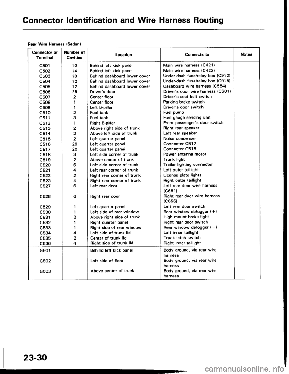
Connector ldentification and Wire Harness Routing
Rear Wire HamsEs (S6danl
Connector ol
Torminal
Number ot
Caviti6sLocaiionConnocts toNotos
c501
c503
c504
c505
c506
c507
c508
c509
c510aEt t
c512
L9 IJ
c514
c515
c516
c517
c518
c519
c520
c521
c522
c523
c527
c52A
LCZY
c530
c531
c532
c533
c534
c535
c536
6
1,|
2
1
I
4
4
10
10
12
25
'I
1
a
1
2
2
20
20
2
6
4
4
6
Behind left kick panel
Behind left kick panel
Behind dashboard lower cover
Behind dashboard lower cover
Behind dashboard lowe, cover
Driver's door
Center floor
Center floor
Left B-pillar
Fuel tank
Fuel tank
Right B'pillar
Above right side of trunk
Above left side ot trunk
Left quarter panel
Left quarter panel
Left quarter panel
Left side corner of trunk
Above center of trunk
Left side corner of trunk
Left rear corner of trunk
Right rear corner of trunk
Right rear corner of trunk
Left ,ear door
Right rear door
LeJt quarter panel
LeJt side oJ rear window
Above right side of trunk
Right quarter panel
Right side of rear window
Left side ot trunk lid
Center ot trunk lid
Right side ot trunk lid
Main wire harness (C421)
Main wire harness (C422)
Under-dash tuse/relay box {C912}
Under-dash fuse/relay box (C915)
Dashboard wire harness (C554)
Driver's door wire harness (C6O l )
Driver's seat belt switch
Parking brake switch
Driver's door switch
Fuel pump
Fuel gauge sending unil
Front passenger's door switch
Right rear speaker
Left rear speaker
Noise condenser
Connector C517
Connector C516
Power antenna motor
Trunk light
Trailer lighting conneclor
Left outer taillighr
License plate lights
Right outer taillighr
Left rear door wire harness
(c651)
Right rear door wire harness
(c656)
Lett rear door switch
Rear window delogget (+ )
High mount btake light
Right rear door switch
Rear window defogger (- )
Left inner taillight
T,unk latch switch
Right inner taillight
G501
G502
G503
Behind lett kick panel
Left side of floor
Above center of trunk
Body ground, via rear wire
narness
Body ground, via rear wire
narness
Body ground, via rear wire
narness
23-30
Page 1195 of 1413
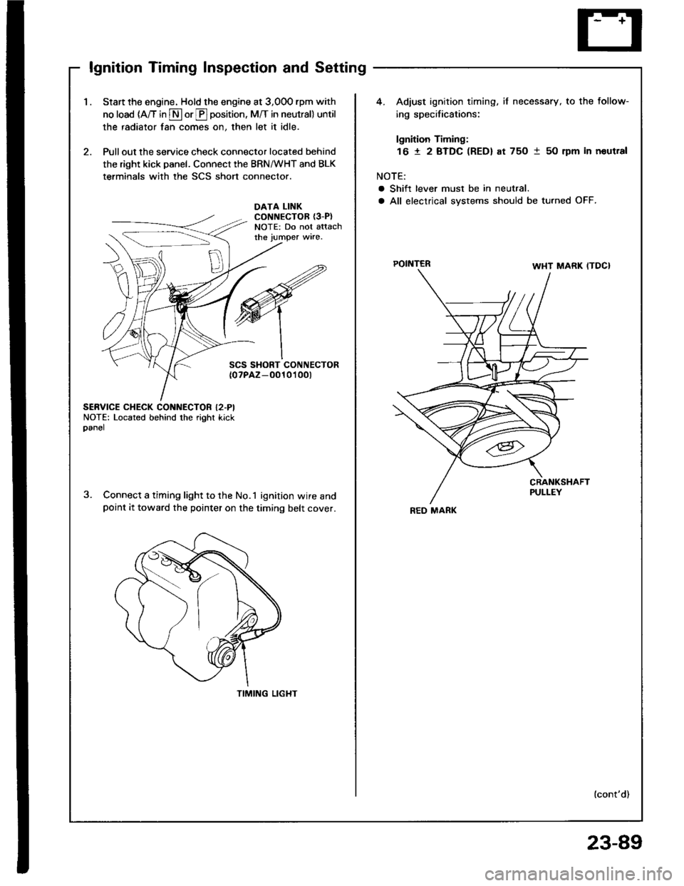
lgnition Timing Inspection and Setting
1.Start the engine. Hold the engine at 3,00O rpm with
no load (A/T in S or E position, M/T in neutral) until
the radiator fan comes on, then let it idle.
Pull out the service check connector located behind
the right kick panel. Connect the BRN/WHT and BLK
terminals with the SCS short connector.
4. Adiust ignition timing, if necessary, to the follow-
ing specifications:
lgnition Timing:
16 t 2 BTDC (RED) at 75O 1 50 rpm in noutral
NOTE:
a Shift lever must be in neutral.
a All electrical systems should be turned OFF.DATA LINKCONNECTOR {3-P}NOTE: Do not attachthe jumper wire.
POINTER
SCS SHORT CONNECTOR{0?PAZ-O010't 00t
SERVICE CHECK CONNECTOR I2.PINOTE: Located behind the right kickoanel
Connect a timing light to the No.1 ignition wire andpoint it toward the pointer on the timing belt cover.
TIMING LIGHT
lcont'd)
REO MARK
23-89
Page 1204 of 1413
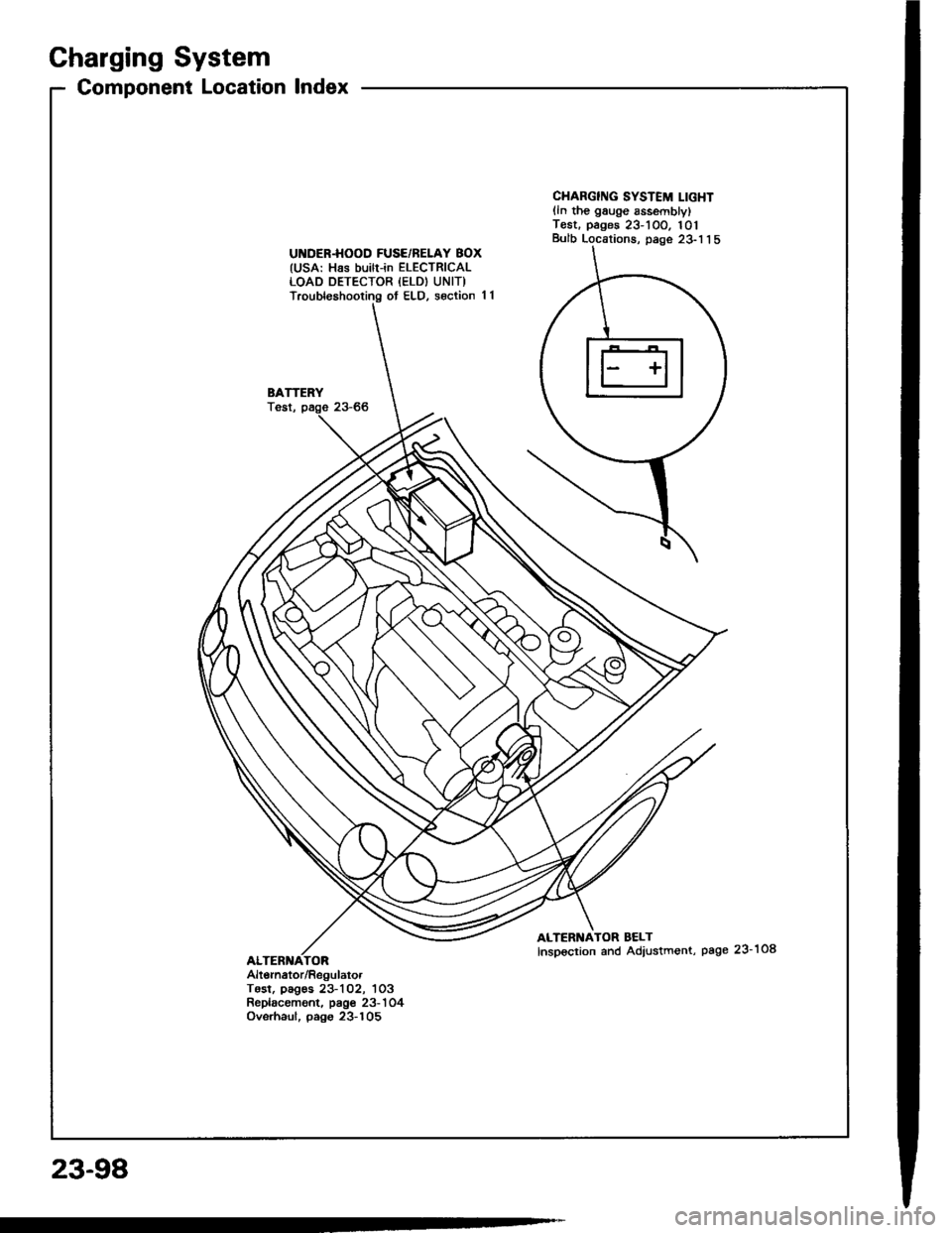
Charging System
Component Location lndex
UI{DER.HOOD FUSE/BELAY BOX(USA: Has builr-in ELECTRICALLOAD DETECTOR {ELD) UNIT)Troubleshooting ot ELD, s€ction 11
BATTERYTost,
CHARGING SYSTEM LIGHTlln the gauge sssemblylT€st. pages 23-1OO. 101Bulb Locations, page 23-1 1 5
ALTERNATOR BELTInspoction and Adiustment, page 23-108
Alt6rnator/RegulatorTosl, pag€s 23-102, 1O3Replacament. page 23-'l 04Ovsrhaul, pago 23-105
23-98
Page 1206 of 1413
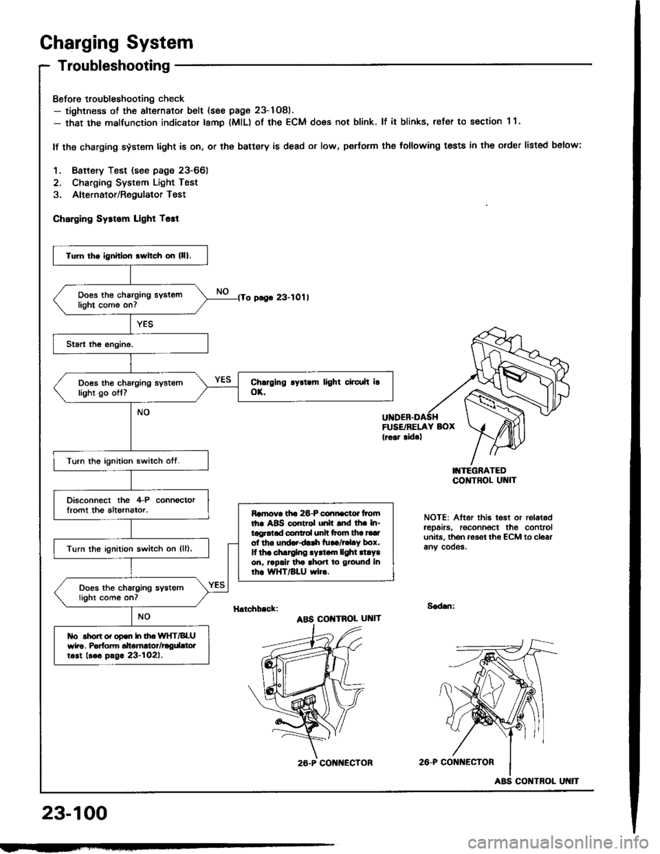
Charging System
Troubleshooting
Bofore troubleshooting check- tightness of the alternator belt (see page 23-1Og).- that the malfunction indicator tamp lMlL) of the ECM does not blink. lf it blinks, refer to section 1 1.
lf the charging system light is on, or th€ battery is dead or low, p€rtorm the following tests in the order listed below:
1. Baftery Test (see page 23-66)
2. Charging System Light Test
3. Alternator/RegulatorTest
ChErging Sysrom Light T6tt
o pago 23-1011
FUSE/RELAY BOX(r..r tid.)
I'{TEGRATEDCO]TTROL UI{IT
NOTE: After this test or relaledrep6irs, roconnoct the controlunits. th6n aoset th€ ECM to cloarany cooos.
H.tchb.ck:Sad.n:
ABS COI{TROL UNIT
2A-P CONi{ECTOR
23-100
Tu]n tho ignhlon srvitch on (lll.
Does th€ charging syslemlight come on7
Does tho charging systemlight go ott?
Turn the ignition switch otf.
Disconnect the 4-P connoctorlromt th€ altornator.Ramova tfto 26-P connactd tromth. ABS control unh snd lh. in-tggrotad conrol unh ttoln tha tadol tho und..dlrh tu!a/r.l.y box.It thr .hlrglng .yrtom lighl .l.Y.on, rrpalr tho ahon to ground Inrhr WHT/BLU wi...
Turn the ignition switch on {ll),
Does the charging systemlight come on?
tlo rhon o. opon h ih. WIfT/BLUwho. Porfom dtomrtor/rogdttolrost beo pag. 23-l02l.
26.P CON ECTOR
ABS CONTROL
Page 1210 of 1413
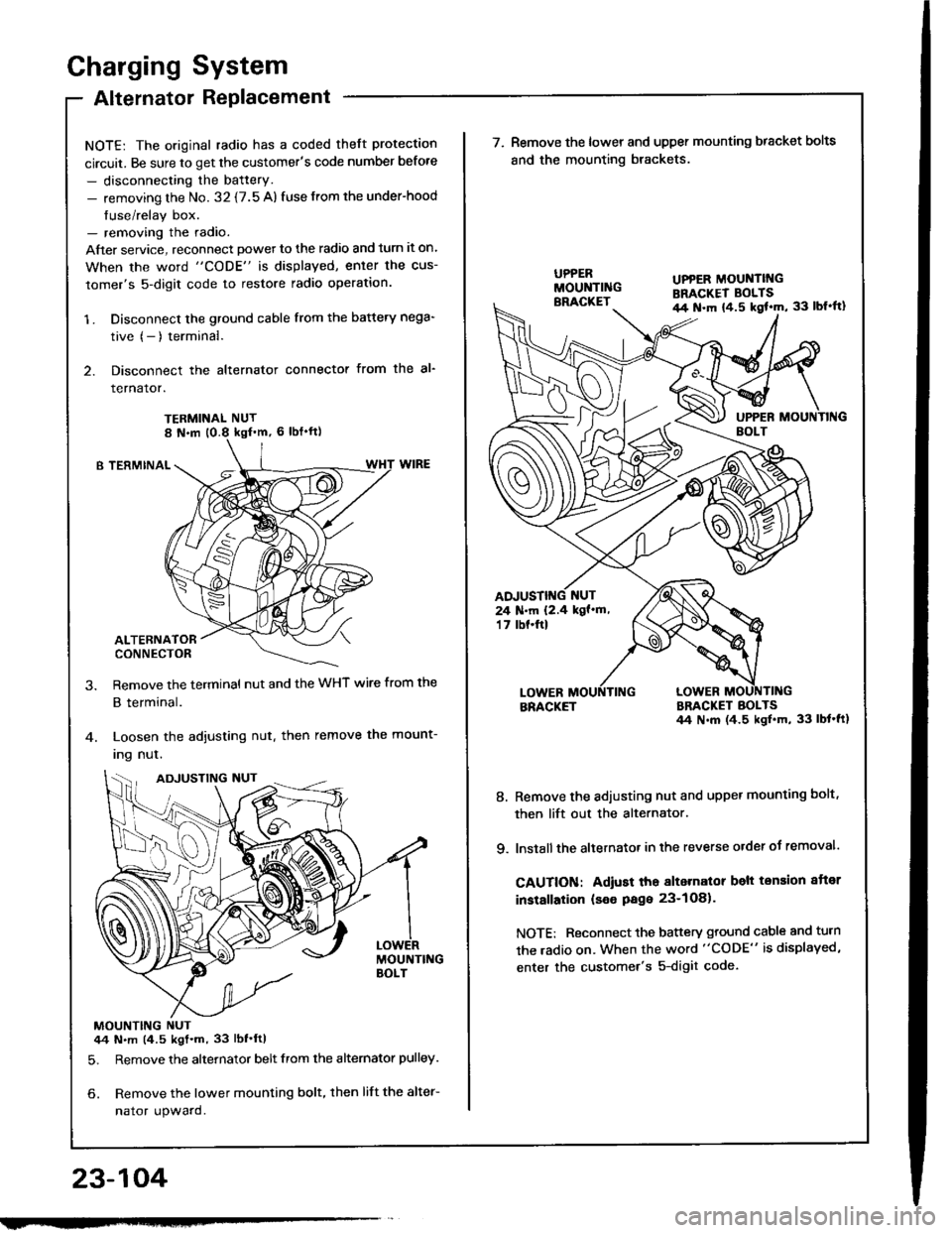
Charging System
Alternator Replacement
NOTE: The original radio has a coded theft protection
circuit. Be sure to get the customer's code number before
- disconnecting the battery.- removing the No. 32 {7.5 A) fuse from the under-hood
fuse/relay box.- removing the radio.
After service, reconnect powet to the radio and turn it on.
When the word "CODE" is displayed, enler the cus-
tomer's 5-digit code to restore radio operation.
1 . Disconnect the ground cable from the battery nega-
tive (- ) terminal.
2. Disconnect the alternator connector from the al-
rernaror.
TERMINAL NUT
B TERMINAL
ALTERNATORCONNECTOR
Remove the terminal nut and the WHT wire from the
B terminal.
Loosen the adjusting nut. then remove the mount-
Ing nul.
MOUNTING NUT44 N.m (4.5 kgt.m, 33 lbf'ftl
5. Remove the alternator belt from the alternator pulley.
6. Remove the lower mounting bolt, then lift the alter-
nator upward.
23-104
ADJUSTING NUT
w
UPPER MOUNTII{GBRACKET BOLTSil4 N.m {4.5 kgl'm, 33 lbl'ft}
24 N.m 12.4 kgf'm,'t 7 tbf.ftl
\ (^,-(\
\-/ I
7. Remove the lower and upper mounting bracket bolts
and the mounting brackets.
BRACKETBRACKET BOLTS44 N.m (4.5 ksl.m, 33 lbt'ft1
8. Remove the adiusting nut and upper mounting bolt,
then lift out the alternator.
9. lnstall the altetnator in the reverse order of removal.
CAUTION: Adiust tho alternalor belt tension aftor
installation (seo Page 23-1O81.
NOTE: Reconnect the battery ground cable and turn
the radio on. When the word "CODE" is displayed,
enter the customer's 5-digit code.