battery harness HONDA INTEGRA 1994 4.G Workshop Manual
[x] Cancel search | Manufacturer: HONDA, Model Year: 1994, Model line: INTEGRA, Model: HONDA INTEGRA 1994 4.GPages: 1413, PDF Size: 37.94 MB
Page 241 of 1413
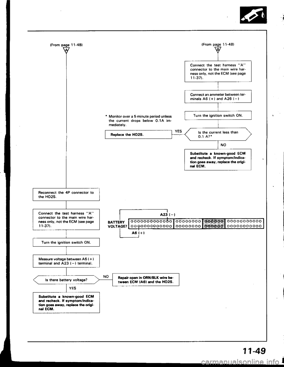
* Monitor over a 5 minute Deriod unl6ssthe current drops below O.1A im-mediatelv.
BATTERYVOLTAGE?
L-E;
o ooooooooo ooo I ooooo oooooooooooooo
oo Qoooooooooo I oooooo ooooooooooooo
Connect the test harness "A"
connector to the main wire harness only, not the ECM (see page
1 1-371.
Connect an ammetet between ter-minals A6 {+ ) and 426 (- )
Turn the ignition switch ON.
ls the current less than0.1 A?.
Subrtitulo s known-good ECM.nd r.ch6ck. lf symptom/indica-tion goes away. roplaco tho origi-n.l ECM.
Connoct the test harn€ss "A"
connector to the main wire har-n6ss only. not th€ €CM {seo page't't-37).
Turn the ignition switch ON.
Measwe vohage bstween A6 {+ }tg.minal and A23 {-)terminal.
Ropsii op6n in ORN/BLK wiro bo-tw..n ECM {A6l and tho HO2S.
Subrtiluto s known{ood ECMlnd Echock. ll .ympiom/indic{-tirn god !way, '.pLc! f|e origl-h.l ECM.
11-49
Page 281 of 1413
ldle Gontrol System
Startel Switch Signal
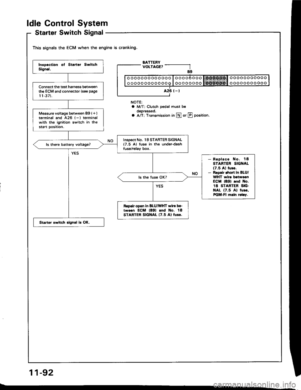
This signals the ECM when the engine is cranking.
BATTERYVOLTAGE?
NOTE:a M/T: Clutch pedal must beoeprgsseo.a A/T: Trsnsmission in lll or LIJ position.
11-92
ooooooooooooo
oooooooooooo
A26 {-}Connect the lest harness botweenthe ECM and connector (see page
11,37).
Measure voltage between 89 (+)
terminal and 426 (-) terminalwith the ignition switch in thestart position.
Inspect No. 18 STARTER SIGNAL{7.5 A) fuse in the under-dashfuse/relav box.ls there batterv voltage?
- Roplac. No. 18STARTER SIG AL(7.5 A) lurc,- Rrpsir lhort In BLU/WHT wir. batwccnECM (89) .nd No.18 STARTER SIG.t{AL {7.5 Al 1u..,PiGM-Fl fi.ln rol.y.
R.palr opon in BLU/WHT wir6 b6-tw€.n ECM lB9l and t{o, 18STARTER SIGNAL 17.5 Al lu.o.
Startor .witch .ign.l is OK.
Page 299 of 1413
Fuel Supply System
Fuel Pump (cont'dl
Tc.ting
@E o" not smoko during tho tesr. Koop openflrmo away fiom your work area.
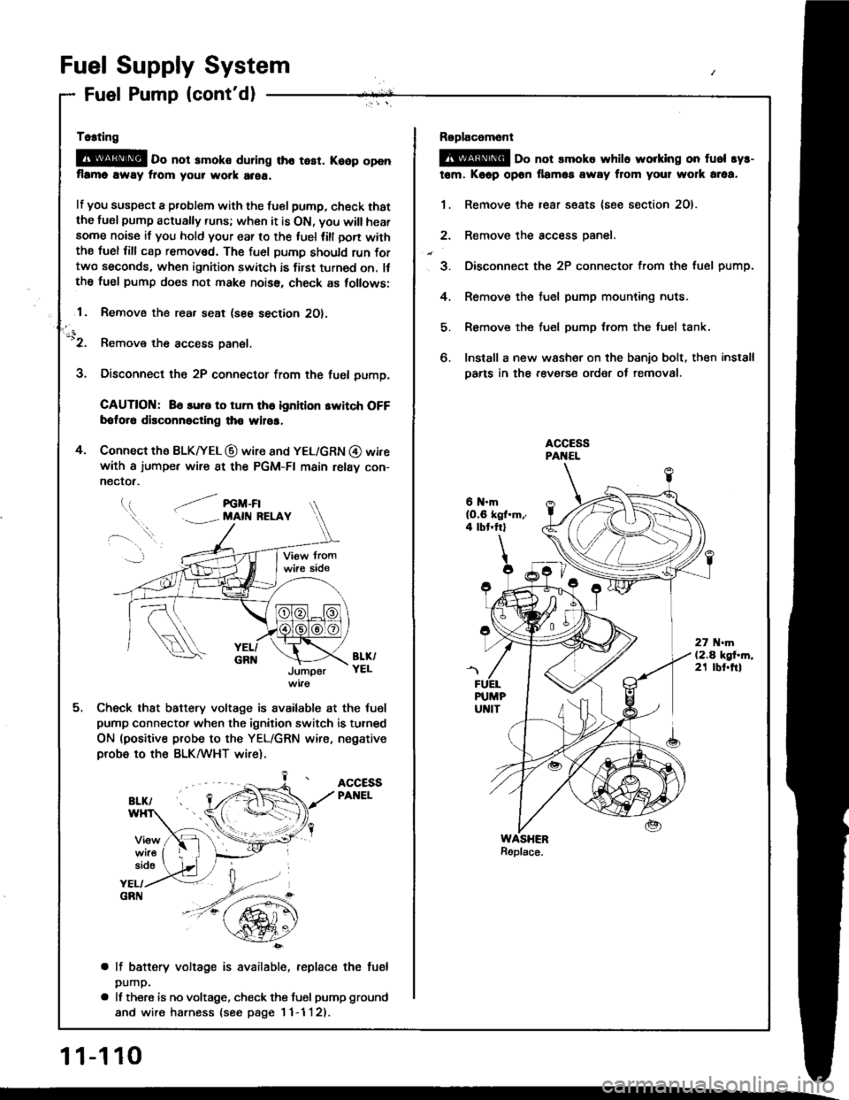
lf you susp€ct a problem with the tuel pump, check thatthe lusl pump actually runs; when it is ON, you will hearsome noise if you hold your ear to the luel lill oon withthe fuel fill cap remov6d. The fuel pumD should run fortwo seconds, when ignition switch is first turned on. llthe fuel pump does not make noiss, check as tollows;
1. Removo the rear seat (see section 2O).
-'2. Remove the access panel.
3. Disconnect the 2P connector from the fuel pump.
CAUTION: 86 lure to tum th6 ignition switch OFFbotor6 disconnoctlng th€ wilos,
4. Connect the BLK|yEL @ wire 8nd YEL/GRN @ wirewith a iumpe. wire 8t the PGM-FI main relav con-
nectot.
l.t, .--/ re -Fl. . MAll{ RELAY
BL&YELJumper
Check that battery voltage is available at the tuel
pump connector when the ignition switch is turned
ON (positive probe to the YEL/GRN wire, negativeprobe to ths BLK/WHT wire).
ACCESSPANEL
side
YEL/GRN
a lf battery voltage is available, replace the fuel
pump.
a It there is no voltage, check the tusl pump ground
and wire harness {see page I 1-1 l2).
11-110
Roplacomont
@ oo not smoks whilo worklng on fuel syr-
tem. Kaop opon llamos away from your wolk araa.
1. Remove the rear ssats {soe section 2O).
2. Remove the access oanel.
3. Disconnect the 2P connector from the fuel pump.
4. Remove the fuel pump mounting nuts.
5. Remove the fuel pump trom the luel tank.
6. Install a new washer on the banio bolt, then install
Darts in the revers€ order of removal.
6 N.mlO.6 kgl.m,.4 tbt.ftl
27 .m(2.4 kgt.m,21 tbt.ftl
Page 314 of 1413
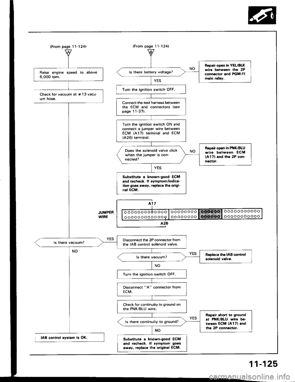
(From page 1 1-124)
Raise engine speed to above6,000 rpm.
Disconnect the 2P connector tromthe IAB control solenoid valve.
Turn the ignition switch OFF.
Check for continuity to ground onthe PNK/BLU wire.
Ropair short to g.ound
at PNK/BLU wiro bo-two6n ECM {A17) andtho 2P connector.
ls there continuity to ground?
Substituto a known-good ECMand racheck. It symptom goos
swsy, roplace tho original ECM.
{From pago 1 1-124}
Repsir op6n in YEL/BLKwiro botwoon tho 2Pconnector and FGM-FImain relaY.
ls there battery voltage?
Turn the ignition swirch OFF.
Connect lhe test harness betweenthe ECM and connectors lseepage 11-37).
Turn the ignition switch ON andconnect a lumper wke betweenECM (A17) terminal and ECM
{A26) terminal.
Ropaiiopon inP K/BLUwiao botwoen ECM
lAl7l and tho 2P con-nectot.
Ooes the solenoid valve clickwhen the jumper is con-nected?
Sub3titute a known-good ECMand rechock. lf symptom/indica-tion goos away, r6place tho origi-nal ECM.
Check lor vacuum at #'l3 vacu-um hose.
IAB control syst6m is OK.
11-125
Page 346 of 1413
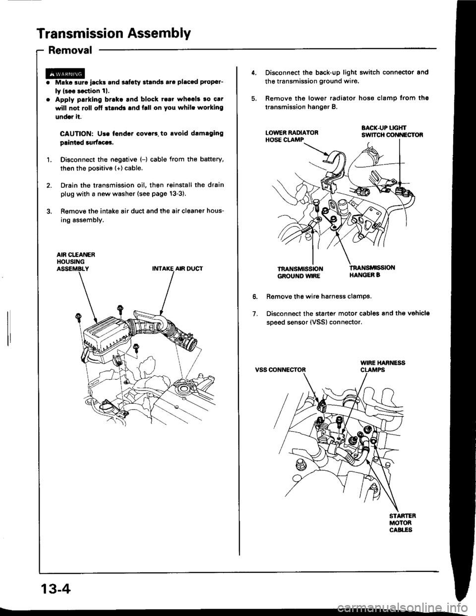
Transmission Assembly
Removal
Mskc aurs iack! and safoty Etands aro placod proper-
ly lsl8 saqtion 1|.
Apply parking brake tnd block rear whccl! to car
will not roll ofl stand3 and f.ll on you while wotking
undrr it.
CAUTION: Use tondcr coyar3. to avoid drmlging
plintsd 3qrfaca3,
Disconn€ct the negative {-) cable from the battery,
then the positive (+) cable.
Drain the transmission oil, then reinstall the drain
plug with a new washer (see page 13-3),
Remove the intake air duct and the air cleaner hous-
ing assembly,
AIR CITANERHOUSING
13-4
4. Disconnect the back-up light switch connoctor and
the transmission ground wir€.
5, Remove the lower radiator hose clamp trom ths
transmission hanger B.
BACK.UP LGHTsuTcH cot{t{EcToR
lnaNsMttistoNGROUND WIRE
tnaNsi ssloNHANGEB B
o.
1.
R€move the wire harness clamPs.
Disconnect the stsrt€r motor cables and the vahicla
soeed sensor (VSS) connector.
VSS OONNECTOR
Page 391 of 1413
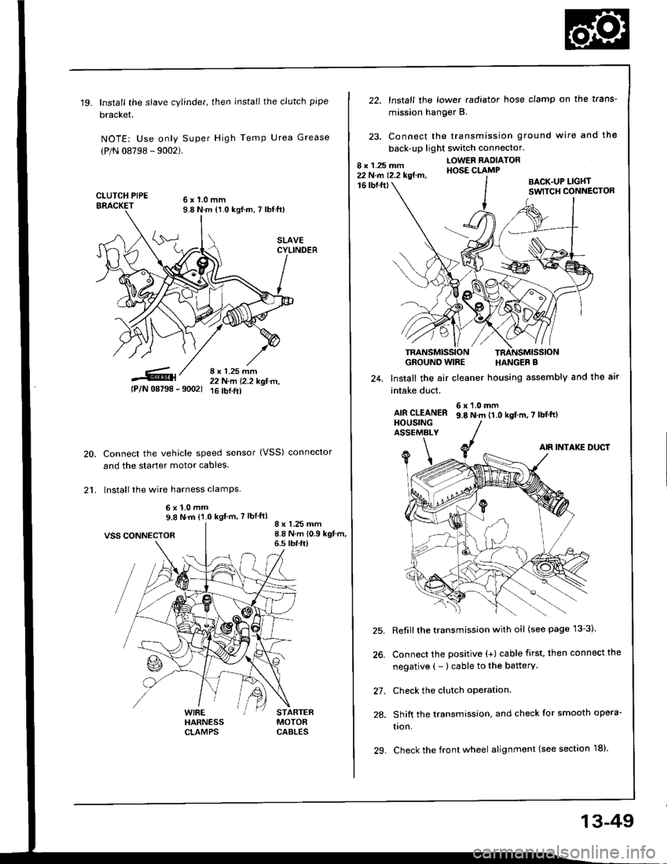
'19.Install the slave cylinder, then install the clutch pipe
bracket.
NOTE: Use only Super High Temp Urea Grease
(P/N 08798 - 9002).
CLUTCH PIPE6x1.0mm9.8 N.m {1.0 kgf.m, 7 lbf ft)
8 x 1.25 mm22 N-m 12.2 kgl.tr't,16 rbf.ftl
20.
21.
tPlN 08798 - 90021
VSS CONNECTOR
Connect the vehicle speed sensor (VSS) conneclor
and the starter motor cables.
Install the wire harness clamPs.
6x1.0mm9.8 N.m (1.0 kgt m,7 lbf ftl
WIREHARNESSCLAMPS
8 x 1.25 mm8.8 N.m 10.9 kgf.m,6.s tbf.ft)
STARTERMOTORCABLES
22, lnstall the lower radiator hose clamp on the trans-
mission hang€r B.
23. Connect the transmission ground wire and the
back-up light switch connector.
16 tbf.fttBACK.UP LIGI{TSWITCH CONNECTOR
GROUND WIRE HANGER B
Install the air cleaner housing assembly and the air24.
intake duct.
AIR CLEANERHOUSINGASSEMALY
6x1.0mm9.8 N.m 11.0 kgt'm,7 lbtftl
AIR INTAKE DUCT
Refill the transmission with oil (see page 13-3).
Connect the positive (+) cable first, then connect the
negative ( - ) cable to the battery.
Check the clutch operation.
Shift the transmission. and check for smooth opera-
tron.
29. Check the front wheel alignment (see section 18).
9\
\<
27.
28.
13-49
Page 450 of 1413
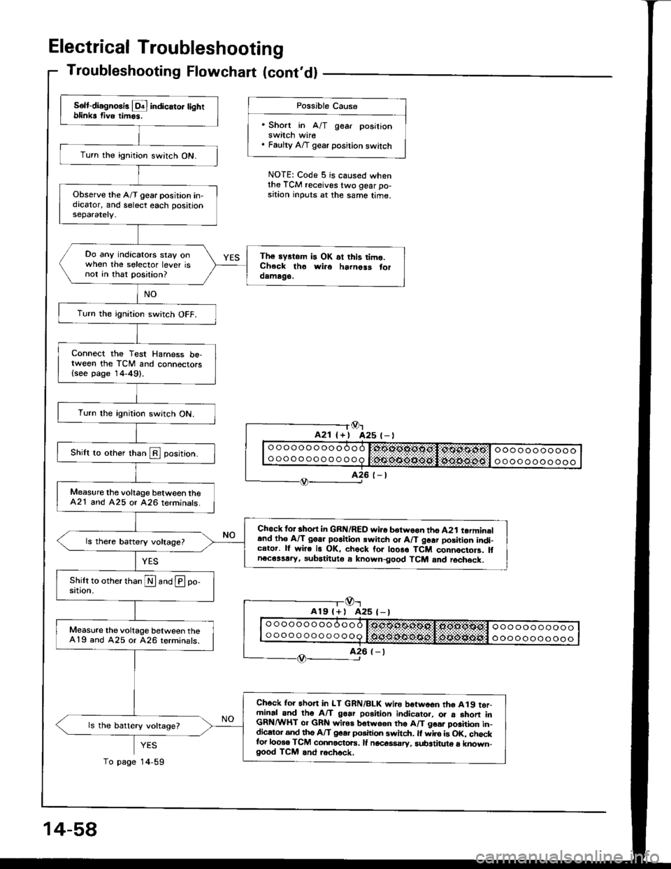
Electrical Troubleshooting
Troubleshooting Flowchart lcont'dl
Possible Cause
'Short in A/T gear posilionswitch wire. Faulty A/T gear position switch
NOTE: Code 5 is caused whenthe TCM receives two gear po-sition inputs at the same time.
Or425 t- |
-l@r
A19l+) A25 (-)
YES
14,59
Solt-diagno8is l!4 indicato. tightblinks fiv6 timos.
Turn the ignition switch ON.
Observe the A/T gear position in-dicator, and select each positionseparately.
Do any indicators stay onwhen the selector lever isnot in that position?
The systom is OK ai this timo.Ch.ck tho wiro ha|noss toroamago.
Turn the ignition switch OFF.
Connect the Test Harness be,tween the TCM and connectors{see page 14-49}.
Turn the rgnition switch ON.
Shilt to other than E position.
Measure the voltage b€tween theA21 and A25 or 426 terminats.
Chock for short in GRN/RED wi.o botwoon tho A2t torminaland th6 A/T goar po6ition swirch or A/T 96ar posirion indi-cator. lf wire is OK, chock for loo8o TCM connocioF. lfnecassary, subatituto a known-good TCM and rochsck.
Measure the voltage between the419 and A25 or 426 terminals.
Ch6ck for 6hon in LT GRN/BLK wi.e borwoon tho A19 tor-minal and tho A/T goar position indicato., o. a shon inGRN/WHT or GRN wiros botwson tho A/T goa. position in-dicato. and tho A/T goa. position swhch. ll wire is OK. chockfor looso TCM connactoE. lf nocos$sry, substituto a known-good TCM and .ech6ck,
ls the battery voltage?
14-58
To page
Page 473 of 1413
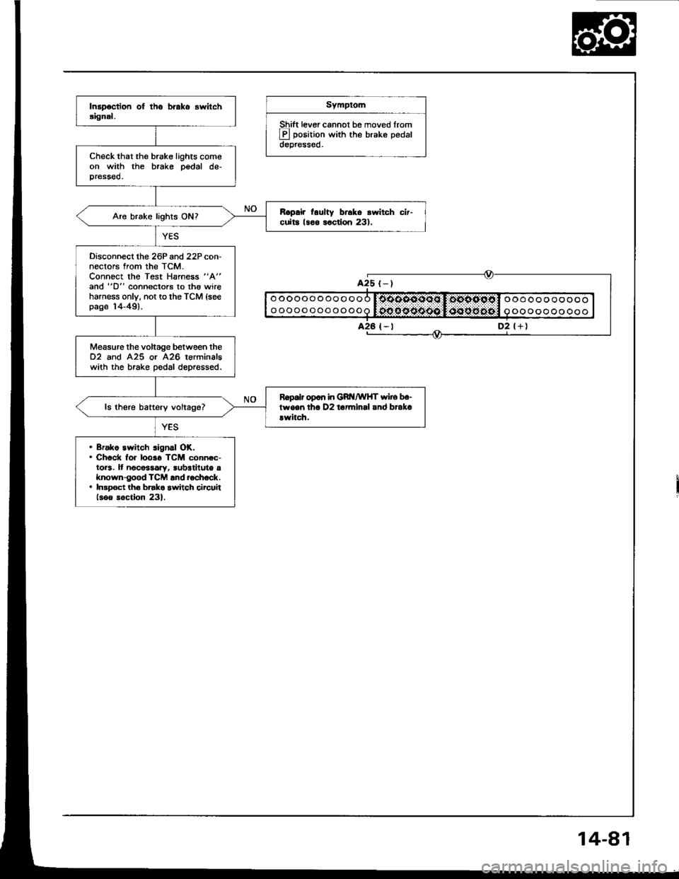
Symptom
Shift lever cannot be moved lrom
E position with the brake pedaldepressed.
Check thar the brake lights comeon with the brake pedal de-pressed.
R.prir l.ulty br6ko rwitch cir-cuita 18o6 lactlon 231.Aro brake lights ON?
Disconnecl lhe 26P and 22P con-nectors from the TCM.Connoct the Test Harness "A"
and "D" coonectors to th€ wireharness only, not to the TCM {seepage 14-49).
Measure the voltage between the02 and 425 or A26 terminalswith the brake pedal dopressed.
Ropalr op6n in GRt{/wHT wiro b.-tween tho D2 to7minsl and brak.!witch.ls there battery voltage?
. Bfako switch signal OK.. Check for 10036 TCM connec-tors. It noco$ary, sub3tiluto aknown-good TCM and ioch6ck.. Insp6ct tho brako switch circuiilsoo soction 23).
oooooooooooo
oooooooooooo
ooooooooooo
oooooooooo
A25 t-)
D2 l+)
Page 491 of 1413
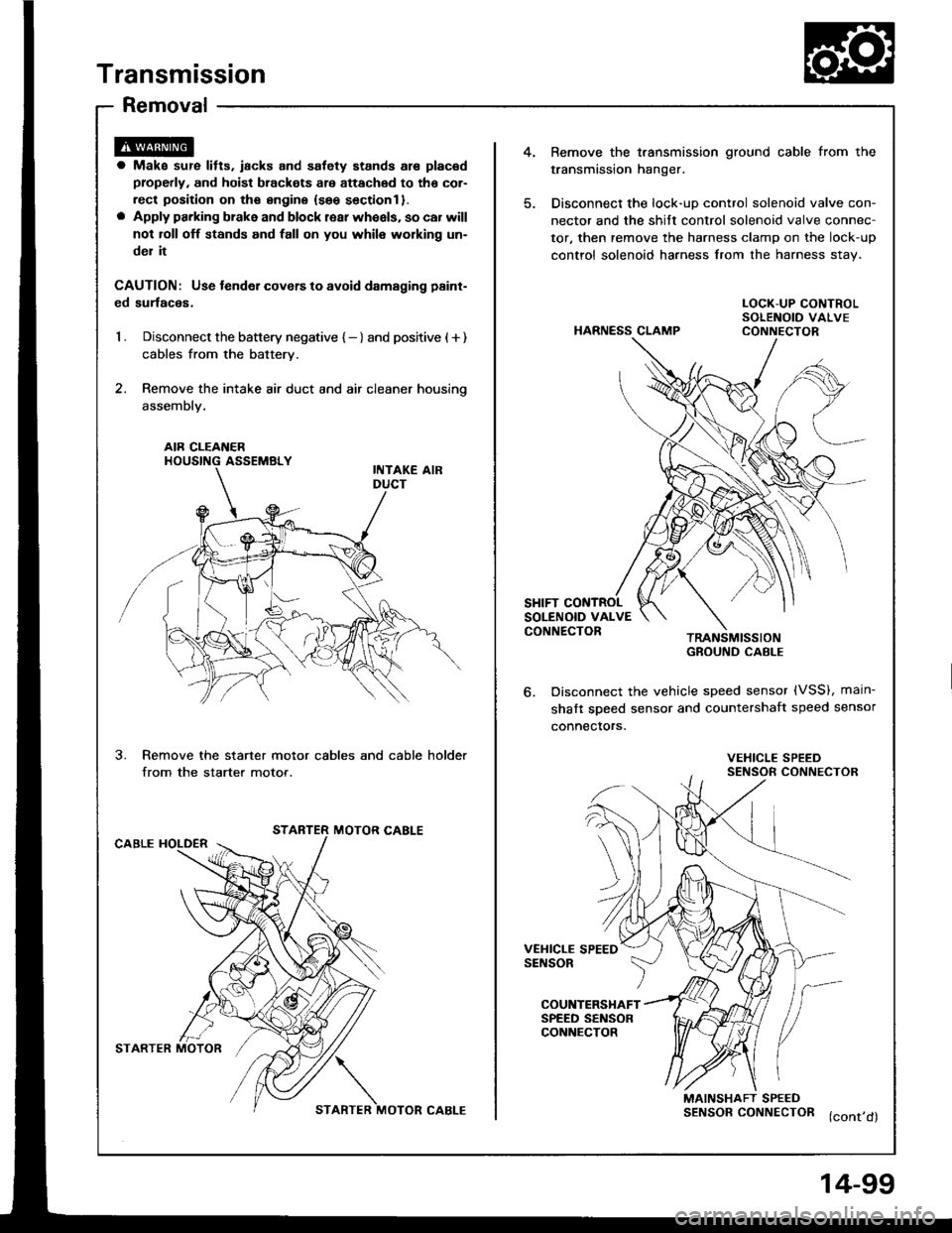
Transmission
Removal
4.Bemove the t.ansmission ground cable from the
transmission hanger.
Disconnect the lock-uD control solenoid valve con-
nector and the shitt control solenoid valve connec-
tor, then remove the harness clamp on the lock-up
control solenoid harness from the harness stav.
a Make sur€ lifts. iacks and safety stands are placad
properly, and hoist brackots are attachod to tho cor-
rect position on ths sngine {seo sectionl }.o Apply parking brake and block rear wheels, so car will
not roll off stands and fall on you whil6 working un-
del it
CAUTION: Use tender covers to avoid damsging paint-
ed surlaces,
1 . Disconnect the battery negative { - } and positive ( + )
cables from the battery.
2. Remove the intake air duct and air cleaner housino
assembly.
HARNESS CLAMP
LOCK-UP CONTROLSOLENOID VALVECONNECTOR
AIR CLEAI{ERHOUSING ASSEMBLY
SHIFT CONTROLSOLENOID VALVECONNECTORTRANSMISSIONGROUND CABI-E
Disconnect the vehicle speed sensor (VSS), main-
shaft sDeed sensor and countershaft speed sensor
connectors.
3.Remove the starter motor cables and cable holder
from the starter motor.VEHICLE SPEEDSENSOR CONNECTOR
STARTER MOTOR CABLECABLE HOLDER
VEHICLE SPEEDSENSOR
COUNTERSHAFTSPEED SENSORCONNECTOR
MAINSHAFT SPEEDSENSORCONNECTOR (cont,d)
STARTER MOTOR?/\
STARTER MOTOR CABLE
4-99
Page 557 of 1413
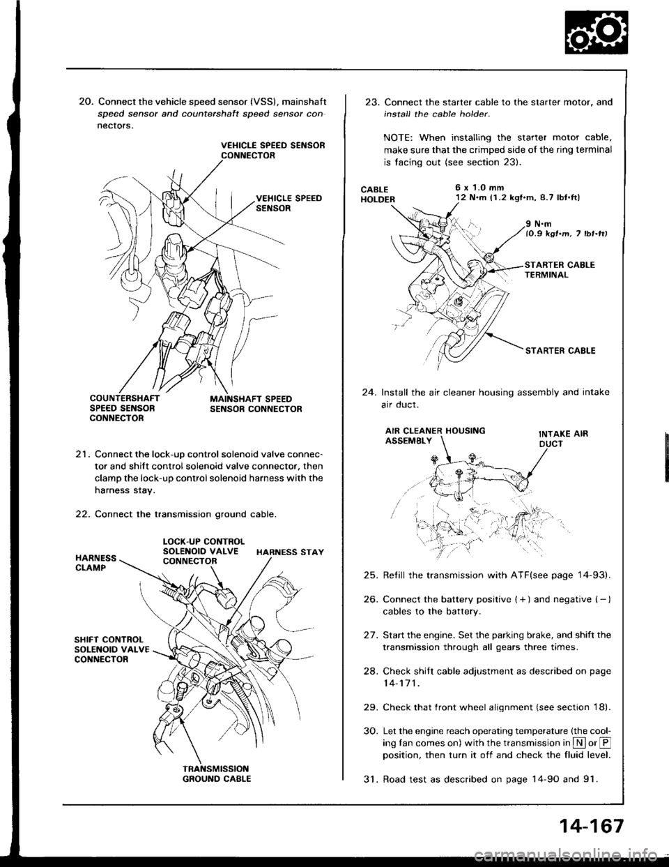
20. Connect the vehicle speed sensor (VSS), mainshatt
speed sensor and counterchalt speed sensor con
nectors.
VEHICLE SPEED SEiISORCONNECTOR
21. Connect the lock-uD control solenoid valve connec-
tor and shift control solenoid valve connector. then
clamp the lock-up control solenoid harness with the
harness stay.
22. Connect the transmission ground cable.
LOCK-UP CONTROLSOLENOID VALVE HARNESS STAY
23. Connect the starter cable to the starter motor, and
install the cable holder.
NOTE: When installing the starter motor cable,
make sure that the crimped side of the ring terminal
is facing out (see section 23).
CABLEHOLDER
6x 1.0 mm'12 N.m (1.2 kgf'm,8.7 lbt.tl)
24.
N.mlO.9 ksr.m, 7 tbr-rtt
STARTER CAELE
Install the air cleaner housing assembly and intake
arr oucl.
AIR CLEANER HOUSINGASSEMBLYINTAKE AIRDUCT
25.
26.
24.
29.
30.
Retill the transmission with ATF(see page '14-93).
Connect the battery positive ( + ) and negative ( - )
cables to the battery.
Start the engine. Set the parking brake, and shift the
transmission through all gears three times.
Check shitr cable adjustment as described on page
14-171 .
Check that front wheel alignment (see section 18).
Let the engine reach operating temperature (the cool-
ing tan comes on) with the transmission in S or @position, then turn it off and check the fluid level.
31. Road test as described on page 14-9o and 91.
14-167