battery replacement HONDA INTEGRA 1994 4.G Workshop Manual
[x] Cancel search | Manufacturer: HONDA, Model Year: 1994, Model line: INTEGRA, Model: HONDA INTEGRA 1994 4.GPages: 1413, PDF Size: 37.94 MB
Page 474 of 1413
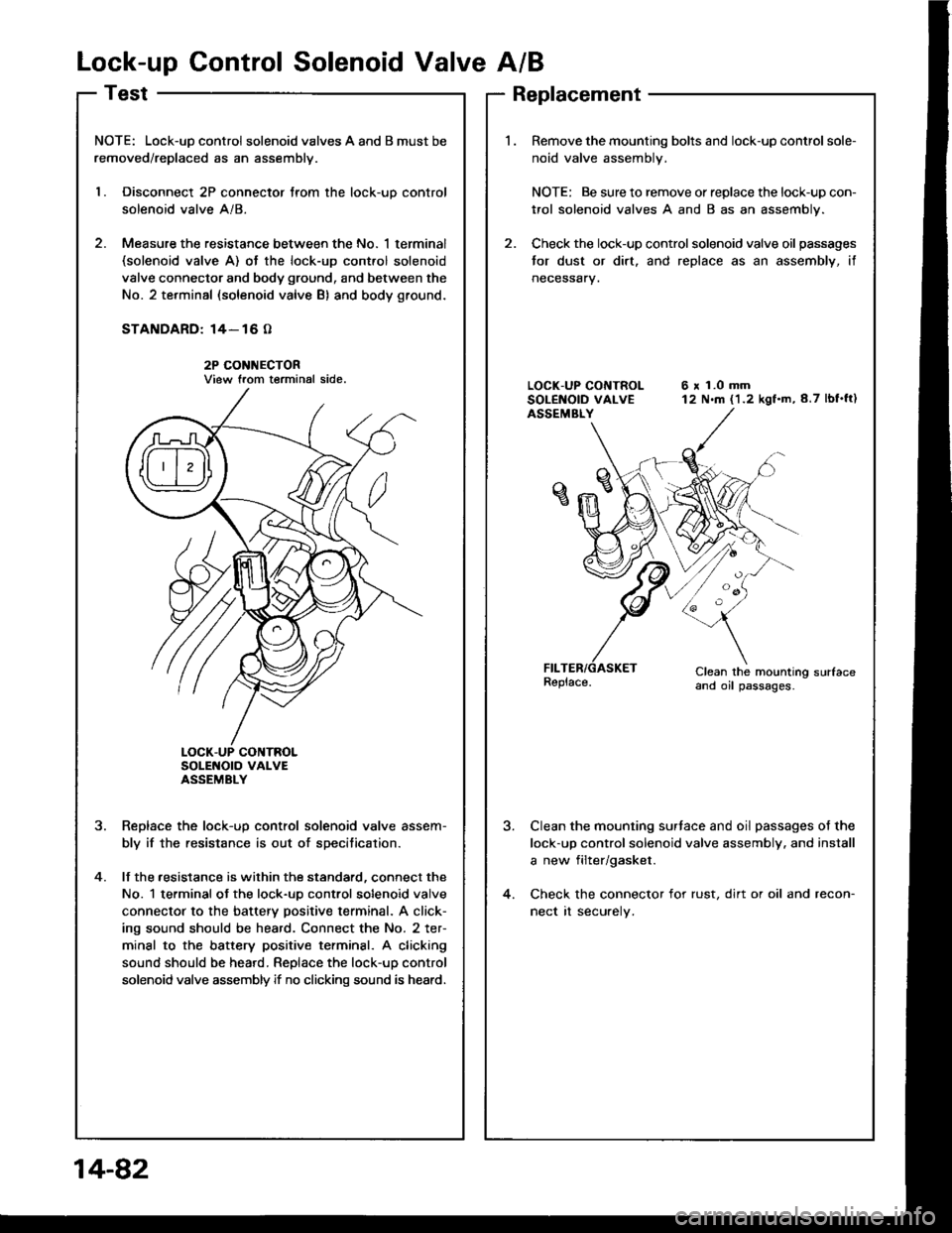
Lock-up Control Solenoid Valve A/B
NOTE: Lock-uD control solenoid valves A and B must be
removed/replaced as an assemblv.
l. Disconnect 2P connector trom the lock-uo control
solenoid valve A/8.
2. Measure the resistance between the No. 1 terminal(solenoid valve A) ot the lock-up cont.ol solenoid
valve connector and body ground, and between the
No. 2 terminal (solenoid valve B) and body ground.
STANDARD: 14- 16 O
2P CONI{ECTORView trom terminal side.
SoLENOTO VAI-VEASSEMBLY
Reolace the lock-uo control solenoid valve assem-
bly if the resistance is out of specitication.
lf the .esistance is within the standard, connect the
No. 1 terminal ot the lock-uo control solenoid valve
connector to the battery positive terminal. A click-
ing sound should be heard. Connect the No. 2 ter-
minal to the battery positive terminsl. A clicking
sound should be heard. Replace the lock-up control
solenoid valve assembly if no clicking sound is heard.
?
4.
Replacement
Remove the mounting bolts and lock-up control sole-
noid valve assembly.
NOTE: Be sure to remove or replace the lock-up con-
trol solenoid valves A and B as an assembly.
Check the lock-up control solenoid valve oil passages
tor dust or dirt. and replace as an assembly, if
neceSsary.
6 x 1.0 mm12 N.m (1.2 kgf.m,8.7 lbf'ft)
Clean the mounting sudaceand oil passages.
Clean the mounting surtace and oil passages of the
lock-up control solenoid valve assembly. and install
a new filter/gasket.
Check the connector for rust, dirt or oil and recon-
nect rt securely.
14-82
Page 608 of 1413
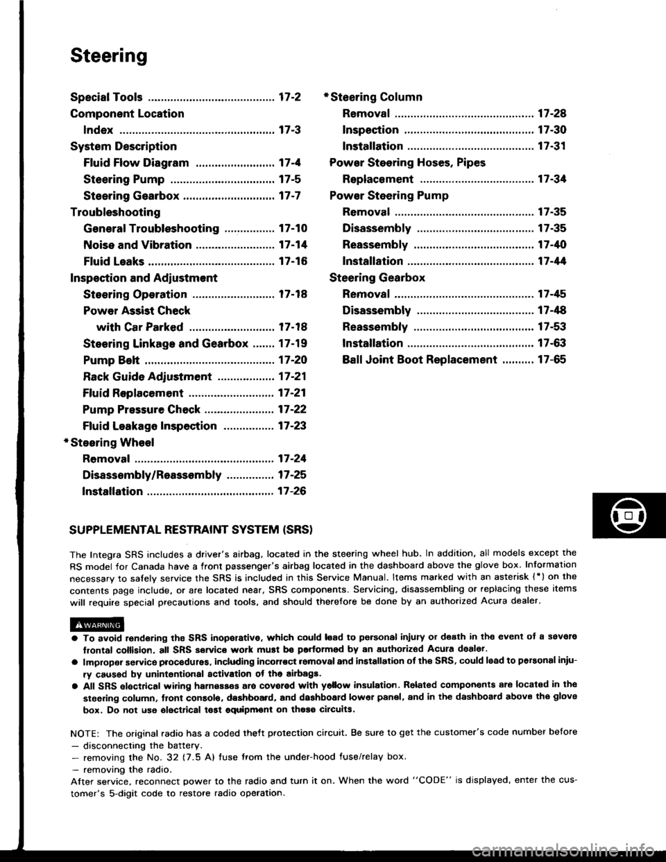
Steering
Special Tools ............. 17-2
Component Location
lndex ................ ...... 17-3
System Description
Ff uid Flow Diagram ......................... 17 -1
Steering Pump ................................. 17-5
Steering Gearbox ............................. 17-7
Troubleshooting
General Troubleshooting ................ 17-10
Noise and Vibration ......................... 17-14
Fluid Leaks ............. 17-16
Inspection and Adiustment
Steoring Operation .......................... 17 -14
Power Assist Check
with Car Parked ........................... 17-18
Steering Linkage and Gearbox ....... 17-19
Pump Beh .............. 17-20
Rack Guide Adjustment ............. ..... 17-21
Ff uid Replacement ...................... ..... 17 -21
Pump Pressure Check .................. .... 17 -22
Ffuid Leakage lnspection ................ 17-23
+ Steering Wheel
Removal ..,,,,,,,........ 17-24
Disassembly/Reassembly ............... 17 -25
fnstallation ,......,,,,,. 17-26
* Steering Column
Removaf .................17-28
Inspection .............. 17-30
Installation ............. 17-31
Power Steering Hoses. Pipes
Replacemont ......... 17-3tl
Power Steering Pump
Removal ................. 17-35
Disassembly .......... 17-35
Reassembly ........... 17-'10
lnstallation ........,..., l7-tltl
Steering Gearbox
Removaf .,.,............. 17-45
Disassembly .......... 17-/E
Reassembly ........... 17-53
lnstallation ............. 17-63
Ball Joint Boot Replacement .......... 17-65
SUPPLEMENTAL RESTRAINT SYSTEM {SRSI
The Integra SRS includes a driver's airbag. located in the steering wheel hub, In addition, all models except the
RS model for Canada have a front passenger's airbag located in the dashboard above the glove box. Information
necessarv to safely service the SRS is included in this Service Manual. ltems marked with an asterisk {') on the
contents page include, or are located near, SRS components. Servicing. disassembling or replacing these items
will require special precautions and tools, and should therefore be done by an authorized Acura dealer.
a To avoid rsndering ths SRS inoporative, which could load to po.sonal iniury 01 d€ath in th€ event ot a ssvare
lrontal collision, all SRS service work muat be performod by an authorizod Acura deal6t.
a lmploper service procodules. including incorloct romoval and installation of the SRS, could lead to personal iniu-
ry caused by unintontional activation ot the airbags.
a All SRS elsctdcal wiring harnesses ara covorod with ysllow insulation. Rolalod compon€nts 8re locatsd in tho
stse ng column, tront console, dashboard, and dashboard lower panel, and in the dashboard above the glove
box. Do not use oloctrical tost equipmoni on thosa cilcuits.
NOTE: The original radio has a coded thett protection circuit. Be sure to get the customer's code number before
- disconnecting the battery.- removing the No. 32 (7.5 A) tuse from the under-hood fuse/relay box.
- removing the radio.
Alter service, reconnect power to the radio and turn it on. When the word "CODE" is displayed' enter the cus-
tomer's 5-digit code to restore radio operation.
Page 1005 of 1413
Dashboard
Replacement Precautions
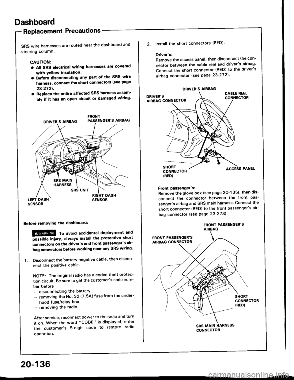
SRS wife harnesses are routed near the dashboard and
steering column.
CAUTION:
a Alt SRS olectrical wiling harness€s ale covorad
with Yollow insulation.
a Botore disconnecting any part ot the SRS wiro
harness, connect ths short connscto6 (see page
23-2721.
a Roplac6 ih€ entiro aflectod SRS halnoss assem-
bly il it has an opon cilcuit or damagod wiling'
LEFT DASHSENSOR
Bstora lomoving the dashboaid:
!@@ To avord accioenlal dsployment and
""iUU inir.v, always install the plotoctive short
;onnectors on the driver's and tlont pass€ngel's air-
bag connectors bolors working near any SRS wiring'
1. Disconnect the battery negative cable, then discon-
necl the positive cable.
NOTE: The original radio has a coded theft protec
tion circuit. Be sure to get the customer's code num-
ber before- disconnecting the battery.
- removing the No 32 (7.5A) Iuse from the under-
hood fuse/relaY box'- removing the radio.
After service, reconnect power to the radio and turn
it on. When the word "CODE" is displayed, enter
the customer's 5 digit code to restore radlo
ooeration.
DRIVER'S AIREAG
SRS UNIT
20-136
DRIVER'S AIRBAG
2.lnstall the short connectors (RED)
Ddvar's:
Remove the access panel, then disconnect the con-
nector between the cable reel and driver's airbag'
Connect the short connector (RED) to the driver's
airbag connector lsee page 23-27 2l'
DRIVER'SAIRBAG CONNECTOB
CABLE REELCONNECTOR
SHORTCONNECTOR(RED)
Front passongor's:
Remove the glove box {see page 20-135}, then dis-
connect the connector between the tront pas'
senger's airbag and SRS main harness Connect the
short connector (RED) to the front passenger's air-
bag connector (see Page 23-273).
FROf{T PASSENGER'SAIRBAG
ACCESS PAI{EL
FRONT PASSET{GER'SAIRBAG CONNECTON
SHORTCONNECTOR(REDI
SBS MAIN HARNESS
CONNECTOR
Page 1039 of 1413
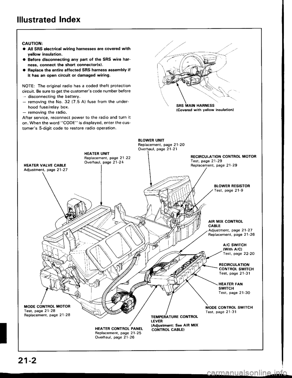
lllustrated Index
CAUTION:
a All SRS electrical wiling harnesses are covered with
y€llow insulation.
a Bafore disconnecting any pan of the SRS wile har-
ness. connect the sholt connectorlsl.
a Replace the sntire aflected SRS halness assembly if
it has an open circuit or damaged wiring.
NOTE: The original radio has a coded thelt protection
circuit. Be sure to get the customer's code number before- disconnecting the battery.- removing the No. 32 (7.5 Al fuse lrom the under-
hood fuse/relav box.- removing the radio.
After service, reconnect power to the radio and turn it
on. when the word "CODE" is displayed, enter the cus-
tomer's 5-digit code to restore radio operation.
BLOWER UNITReplacement, page 21-2OOverhaul, page 21-21HEATER UNITRepfacement, page 2l 22Overhaul, page 21-24
RECIRCULATION CONTROL MOTORTest, page 21-29Replacement, page 21 29I{EATER VAIVE CABLEAdjustment, page 21-27
BLOWEN RESISTORTest, page 21-9
AIR MIX CONTROLCABLEAd,ustment, page 21-27Replacement. page 21-26
a/c swrTcH(wirh A/clTest, page 22-20
RECIRCULATIONCONTROL SWITCHTest, page 21-31
HEATER FANswtTcHTest, page 2'l-3O
MODE CONTROL MOTORTest, page 21-28Repfacement, page 21'28
MODE CONTROL SWITCHTest, page 21'31
HEATER CONTROL PANELRepf acement, page 21 -25
Overhaul, page 21-26
TEMPERATURE CONTROLLEVER(Adjustmonl: See AIR MIXCONTROL CABLE}
SRS MAIN HARNESS
W,
21-2
I
Page 1065 of 1413
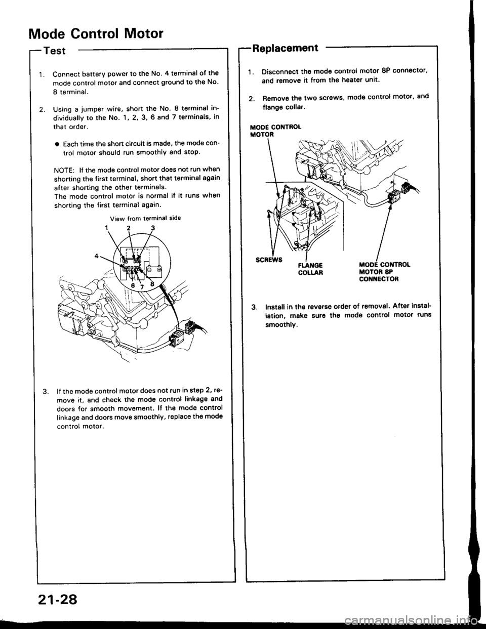
Mode Control Motor
Test
Connect batterY power to the No. 4 terminsl of the
mode control motor and connect ground to the No'
8 terminal.
Using a jumper wire, short the No. 8 terminsl in-
dividually to the No. 1, 2, 3. 6 and 7 terminals, in
that order.
a Each time the short circuit is mad€, the mode con-
trol motor should run smoothly and stop.
NOTE: ll the mode control motor does not run when
shorting the tirst terminsl, short that t€rminal again
after shorting the other terminals.
The mode control motor is no.mal it it runs when
shorting the tirst terminal again.
lf the mode control motor does not run in step 2, re'
move it, and check ths mode control linkage 8nd
doors for smooth movement. It the mod€ control
linkage and doors move smoothly, replace th€ mod€
control motor.
Disconnoct ths mode control motot 8P connector,
and remove it from lhe heater unit.
Remove the two sclsws, mode control motot, and
flango coll8,.
MODE CONTROLiioroR
3. lnst8ll in tho rsvsrse order of removal. After inst8l-
lstion, make sur€ the modo control motor runs
smoothlv.
Replacement
21-28
Page 1071 of 1413
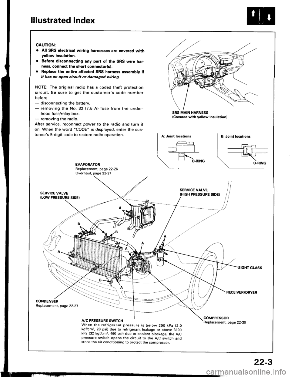
lllustrated Index
CAUTION:
. All SRS electrical wiring harnossos are cover€d withyellow insulation.
. B€fors disconnacting any part of the SRS wire har-ness, connsct the 3hort connsctor(s).. Replace the entirs affscted SRS harness assembly itit has an open circuit or damaged wiring.
NOTE; The original radio has a coded theft protection
circuit. Be sure to get the customer's code number
before- disconnecting the battery.- removing the No.32 (7.5 A) fuse from the under-
hood fuse/relay box.- removing the radio.
After service, reconnect Dower to the radio and turn it
on. When the word "CODE" is displayed, enter the cus-
tomer's 5-digit code to restore radio operation.
SRS MAIN HARNESSlcover€d with yellow insulationl
EVAPORATORReplacement, page 22-26Ovethaul. Oase 22.27
SERVICE VALVE(LOW PRESSURE SIDEI
SERVICE VALVEIHIGH PRESSURE SIDE)
RECEIVER/DRYER
CONDENSERReplacement, page 22,37
A/C PRESSURE SWITCHCOMPRESSORReplacement, page 22-30When the refrigerant pressure is below 200 kpa (2.0kqflcm,,28 psi) due to refrigerant leakage or above 3]OOkPa (32 kgf/cm,, 460 psi) due to coolant btockage, the A,/Cpressure switch opens the circuit to the A"/C switch andstops the air conditionang to protect the compressor.
22-3
Page 1177 of 1413
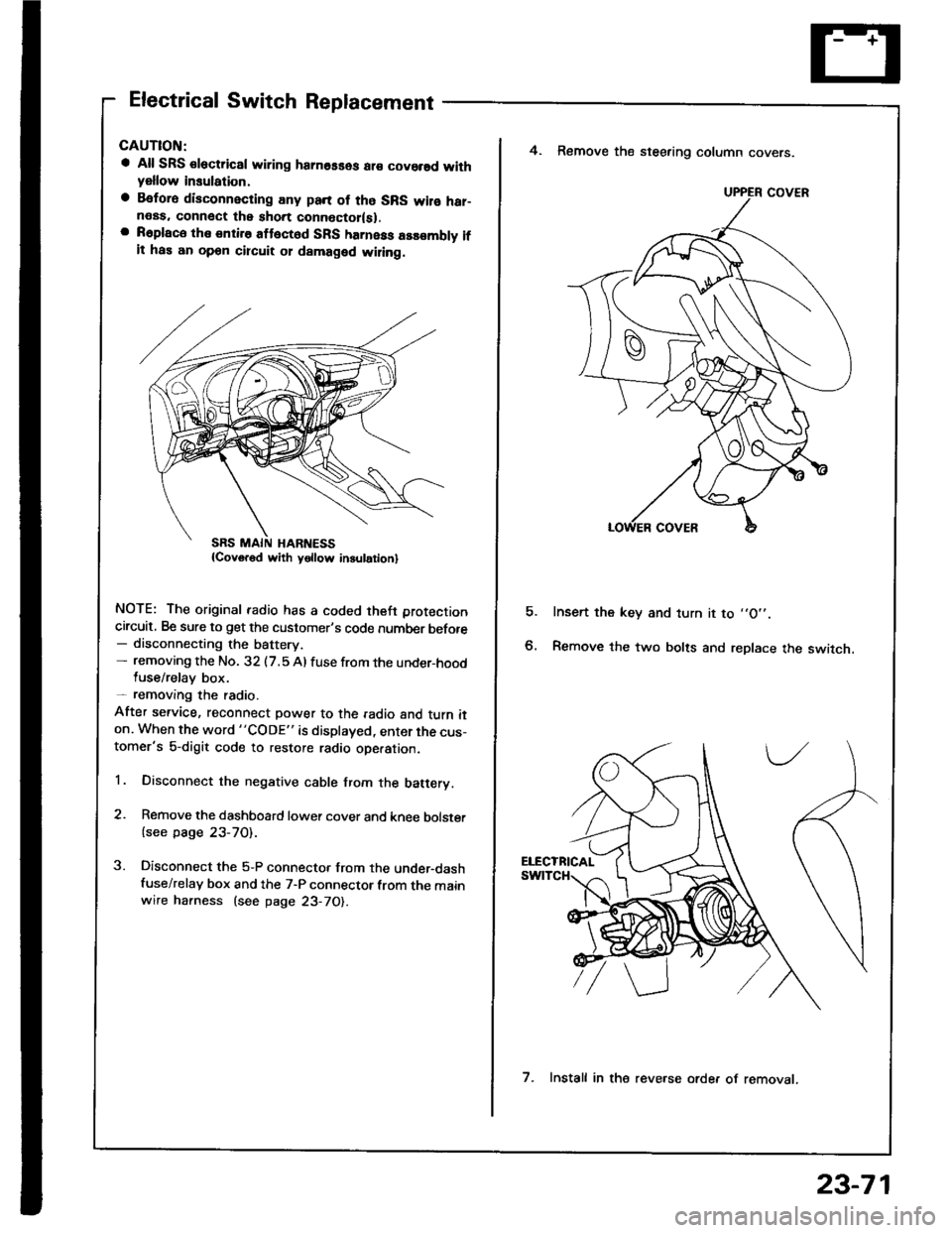
Electrical Switch Replacement
a All SRS €lectric8l wiring hamosses ar€ covorsd withyellow insulation,
a Befora disconnecting any pan of tho SRS wilo har-neas. connect the short connoctor(sl.a R6place the entire attect6d SFS harness assombly ifit has an opon circuit 01 damaged wiling.
NOTE: The original radio has a coded theft protection
circuit, Be sure to get the customer's code number before- disconnecting the battery.- removing the No. 32 (7.5 Al fuse from the under-hoodluse/relay box.- removang the radio.
After service, reconnect power to the radio and turn iton. When the word "CODE" is displayed, enter the cus-tomer's 5-digit code to restore radio ope.ation.
1. Disconnect the negative cable from the batery.
2. Remove the dashboard lower cover and knee bolster
{see page 23-70).
3. Disconnect the 5-P connector from the under-dashfuse/relay box and the 7-P connector from the mainwire harness (see page 23-70).
E
4. Remove the steering column covers.
Insert the key and turn it to ,,O',.
Remove the two bolts and replace the switch.
UPPER COVER
7. Install in the reve.se orde. of removat.
23-71
Page 1178 of 1413
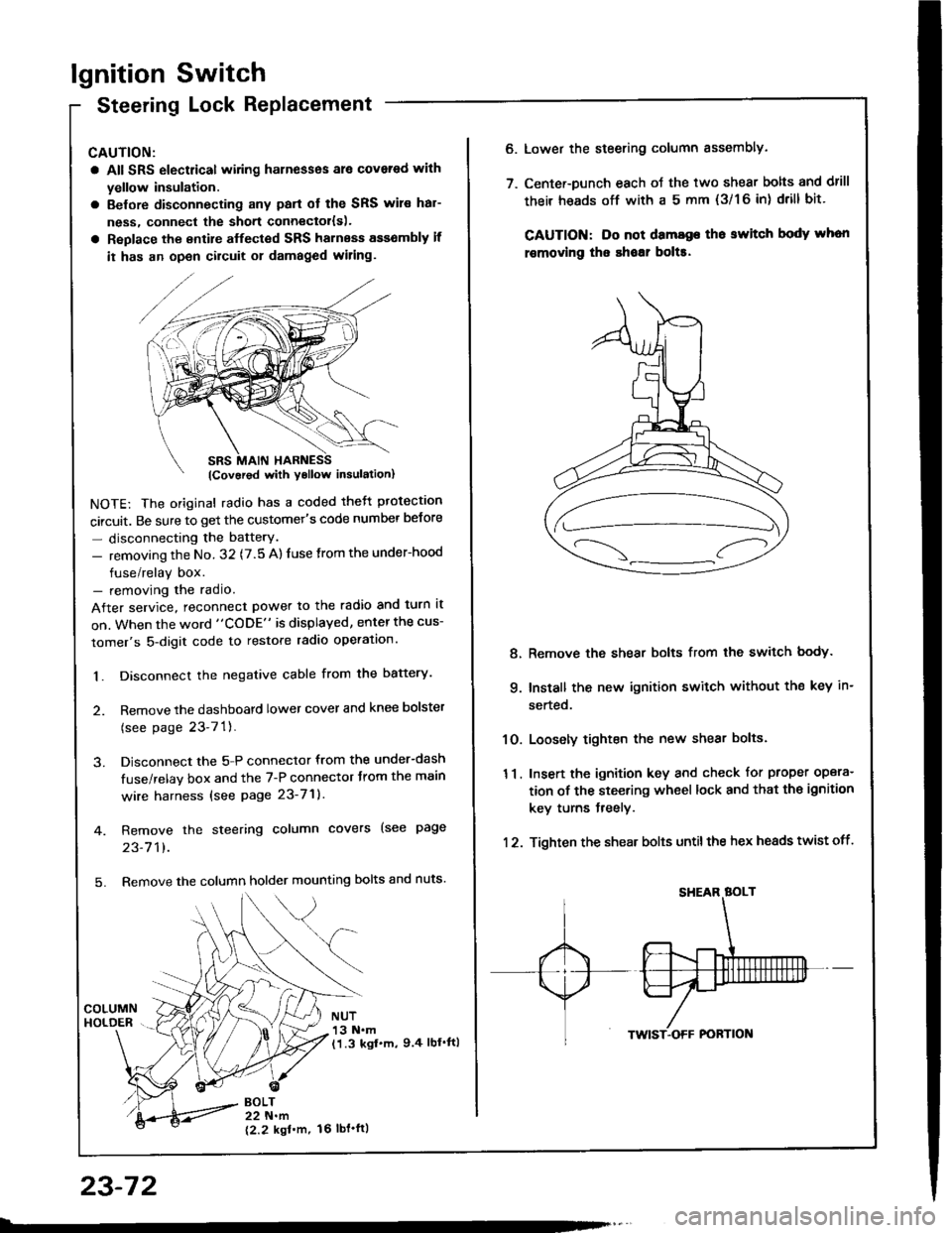
lgnition Switch
Steering Lock Replacement
CAUTION:
a All SRS electrical wiring harnesses ale covsred with
yellow insulation.
a Belore disconnecting any parl ot the SRS wir€ hal-
ness, connecl the short connector{s).
a Replace the entire alfected SRS harness a$6mbly il
it has an open circuit or damaged wiring.
NOTE: The original radio has a coded thett protection
circuit. Be sure to get the customer's code number betore
- disconnecting the batterY.
- removing the No. 32 (7.5 A) fuse from the under-hood
fuse/relay box.- removing the radio.
After service, reconnect power to the radio and turn it
on. When the word "CODE" is displayed, enter the cus-
tomer's 5-digit code to restore radio operation.
1. Disconnect the negative cable from the battery.
2. Remove the dashboald lower cover and knee bolster
(see page 23-7'l ).
3. Disconnect the 5-P connector from the under-dash
fuse/relay box and the 7-P connector trom the main
wire harness {see page 23-71).
4. Remove the steering column covers (see page
23-711.
5. Remove the column holder mounting bolts and nuts'
BOLT22 N.m
12.2 kgl'm.
NUT13 N.m(1.3 kgf.m, 9.4 lbl'ftl
23-72
16 tbt.ftl
6. Lower the steering column sssembly.
7. Center-Dunch each oJ the two shear bolts and drill
their heads off with a 5 mm {3/1 6 in) drill bit'
CAUTION: Do not dama96 tho switch body whon
r€movlng the shoar bol$.
Remove the shear bolts from the switch body.
Install the new ignition switch without the key in-
serted.
Loosely tighten the new shear bolts.
Insert the ignition key and check for proper opera-
tion of the steering wheel lock and that th€ ignition
key turns freely.
Tighten the shear bolts untilthe hex heads twist off.
8.
q
10.
11.
12.
Page 1210 of 1413
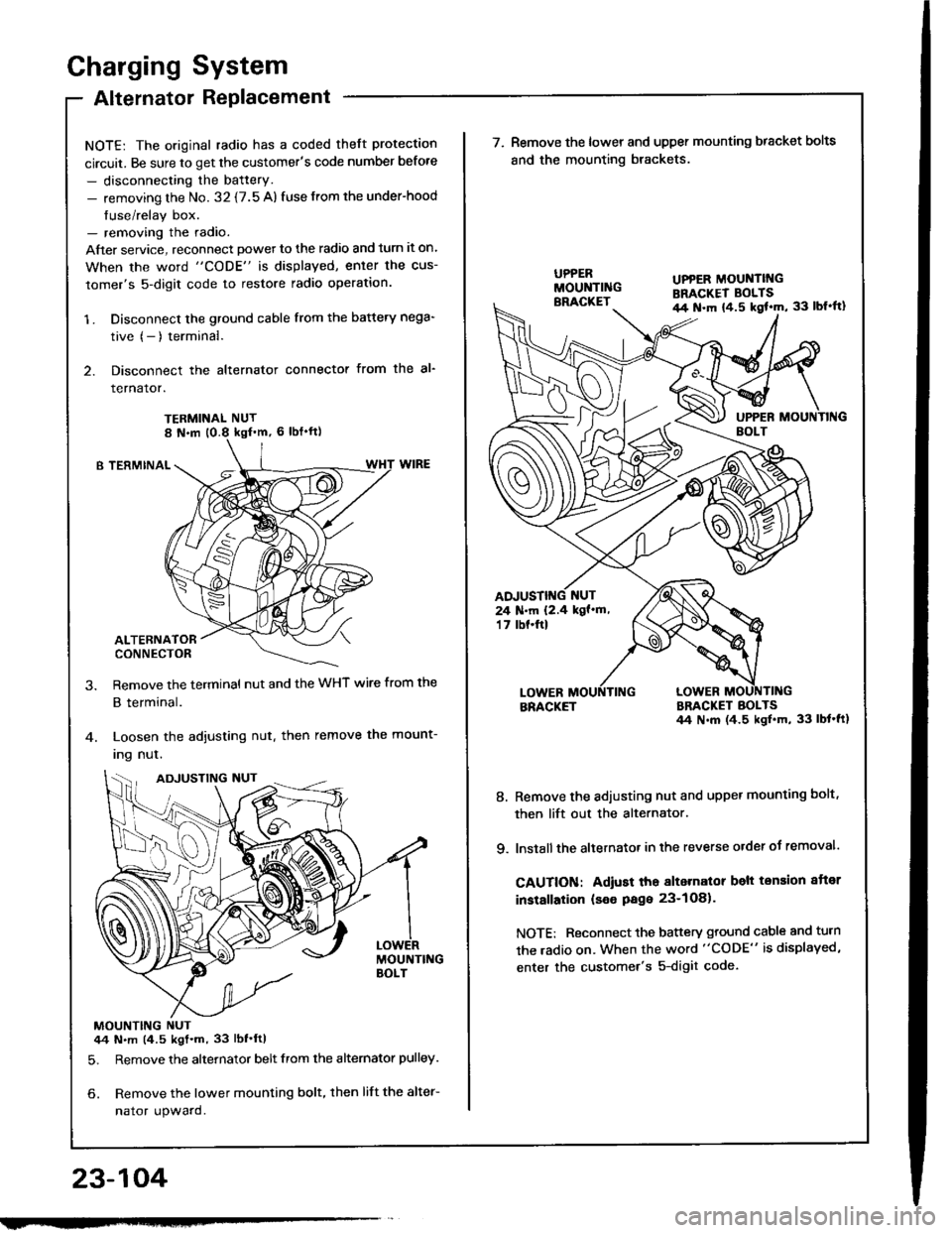
Charging System
Alternator Replacement
NOTE: The original radio has a coded theft protection
circuit. Be sure to get the customer's code number before
- disconnecting the battery.- removing the No. 32 {7.5 A) fuse from the under-hood
fuse/relay box.- removing the radio.
After service, reconnect powet to the radio and turn it on.
When the word "CODE" is displayed, enler the cus-
tomer's 5-digit code to restore radio operation.
1 . Disconnect the ground cable from the battery nega-
tive (- ) terminal.
2. Disconnect the alternator connector from the al-
rernaror.
TERMINAL NUT
B TERMINAL
ALTERNATORCONNECTOR
Remove the terminal nut and the WHT wire from the
B terminal.
Loosen the adjusting nut. then remove the mount-
Ing nul.
MOUNTING NUT44 N.m (4.5 kgt.m, 33 lbf'ftl
5. Remove the alternator belt from the alternator pulley.
6. Remove the lower mounting bolt, then lift the alter-
nator upward.
23-104
ADJUSTING NUT
w
UPPER MOUNTII{GBRACKET BOLTSil4 N.m {4.5 kgl'm, 33 lbl'ft}
24 N.m 12.4 kgf'm,'t 7 tbf.ftl
\ (^,-(\
\-/ I
7. Remove the lower and upper mounting bracket bolts
and the mounting brackets.
BRACKETBRACKET BOLTS44 N.m (4.5 ksl.m, 33 lbt'ft1
8. Remove the adiusting nut and upper mounting bolt,
then lift out the alternator.
9. lnstall the altetnator in the reverse order of removal.
CAUTION: Adiust tho alternalor belt tension aftor
installation (seo Page 23-1O81.
NOTE: Reconnect the battery ground cable and turn
the radio on. When the word "CODE" is displayed,
enter the customer's 5-digit code.
Page 1249 of 1413
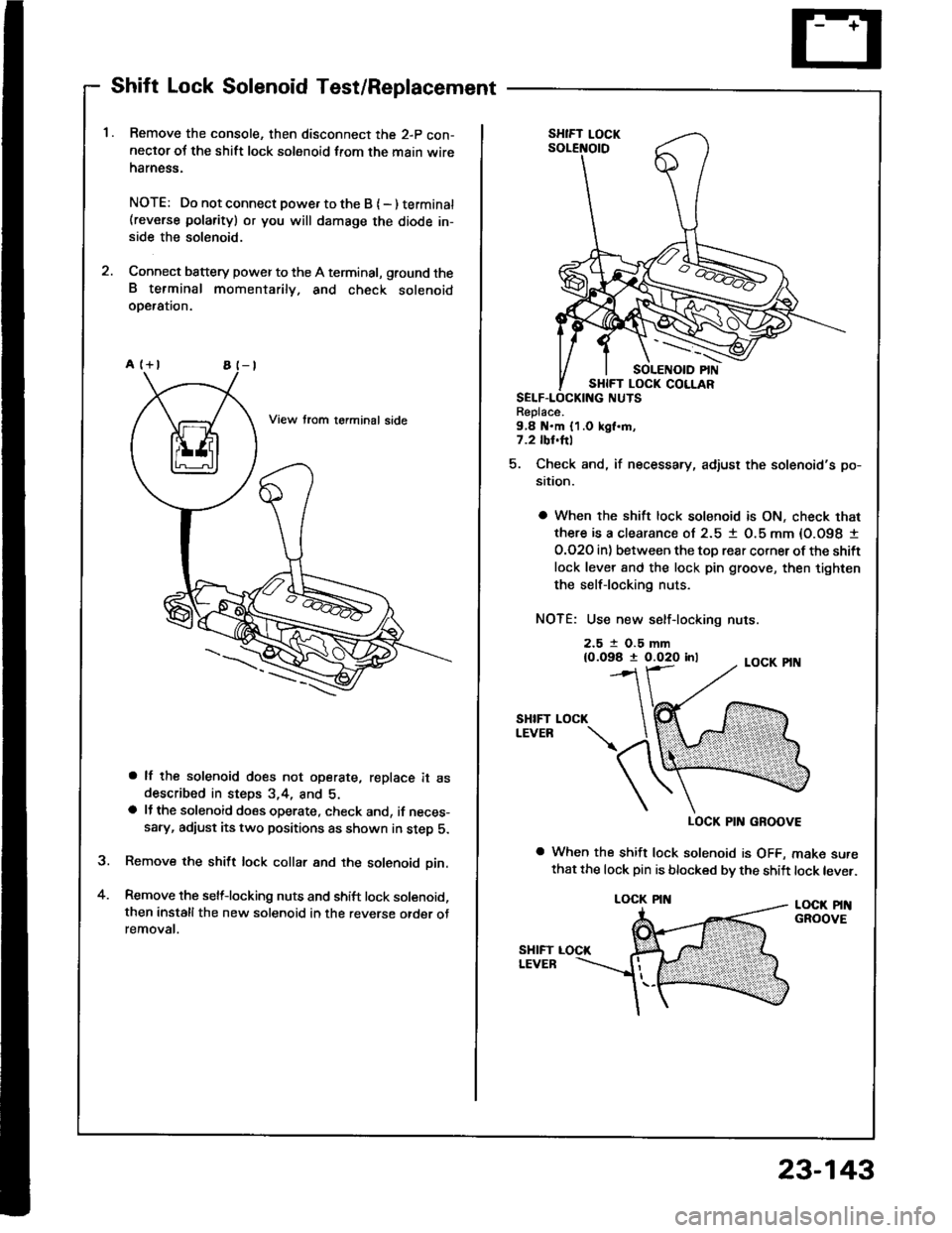
Shift Lock Solenoid Test/Replacement
Remove the console, then disconnect the 2-p con-neclor oJ the shift lock solenoid from the main wireharness.
NOTE: Do not connect powe. to the B { - ) terminat(reverse polarity) or you will damsge the diode in-side the solenoid.
Connect battery power to the A terminal, ground theB terminal momentarily. and check solenoidoDeralron.
a lf the solenoid does not operate, replace it asdescribed in steps 3,4, and 5.a lJ the solenoid does operate, check and, if neces-sary, adiust its two positions as shown in step 5.
Remove the shift lock collar and the solenoid pin.
Remove the selflocking nuts and shift lock solenoid,then installthe new solenoid in the reverse otder otremovat.
a
Replace.9,8 N.m {1.0 kgl.m,7.2 tbl.hl
5. Check and, if necessary, adjust the solenoid's po-
sition.
a When the shift lock solenoid is ON, check that
there is a clearance ol 2.5 1 O.5 mm {O.O98 I
O.O2O in) between the toD rear corner ot the shift
lock lever 8nd the lock pin groove, then tighten
the selflocking nuts.
NOTE: Use new self-locking nuts.
2.5 t O.5 mm{0.098 t 0.020 inl
SHIFTLEVEB
LOCK PIN GROOVE
a When the shift lock solenoid is OFF, make surethat the lock pin is blocked bv the shift lock lever.
LOCK PINGROOVE
LOCK
LOCK PIN
23-143