connector or terminal HONDA INTEGRA 1994 4.G Workshop Manual
[x] Cancel search | Manufacturer: HONDA, Model Year: 1994, Model line: INTEGRA, Model: HONDA INTEGRA 1994 4.GPages: 1413, PDF Size: 37.94 MB
Page 48 of 1413
Engine Removal/lnstallation
@a Make sure jacks and safety stands aro placed ploper-
ly and hoisl brackots arg attachod to the correct po-
sitions on tho engine (se€ ssction 1).
a Mak€ sure tho car willnot roll off stands and tallwhile
you are wotking under it'
CAUTION:
a Use fendet covals to avoid damaging painted
sudaces.
r Unspecified itsms alo common
a Unplug tho widng connectots carefully while holding
the couplor and tha connector portion to avoid
oamage.
a Mark all wiring and hoses to avoid misconnection.
Also, be sulo that thsy do not contact other wiring
or hoses, or interfere with oth€l parts.
NOTE: Anti-theft radios have a coded theft ptotection
circuit. Be sure to get the customer's code number beJore
- Disconnecting the batterY.
- Removing the No. 32 (7.5 A) fuse from the under-
hood tuse/relay box.- Removing the radio
Atter service, reconnect power to the radio and turn it
on. When the word "CODE" is displayed, enter the cus-
tomer's 5-digit code to restore radio operataon.
1. Remove the hood (see section 2O).
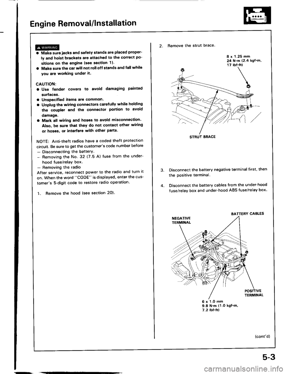
2. Remove the strut brace
8 x 1.25 mm24 N.m (2.4 kgf.m,17 rbt.ft)
Disconnect the battery negative terminal lirst. then
the positive terminal.
Disconnect the battery cables from the undel-hood
fuse/relay box and under-hood ABS fuse/relay box.
6 x l.O mm9.8 N.m (1 .O kgf'm,7.2 rbl.ftl
{cont'd)
STRUT ERACE
BATTERY CABLES
5-3
Page 98 of 1413
{From pag6 636}
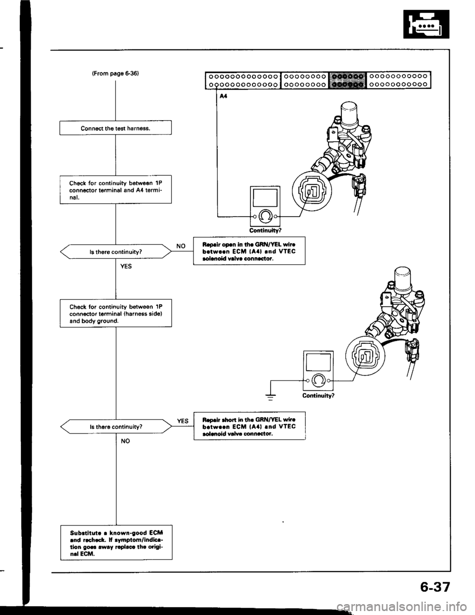
ContinuityT
ooooooooooo
ooooooooooo
ooooooooooooo
ooooooooooooo
Ch6ck for continuity botw6en 'lP
connector t€rminal and A4 termi-nal.
B.9.lr op.n in th. GRI{/YEL wircb.tw..n ECM {Aa} .od vTEcaolanoid valva connac'tor.
Ch6ck for continuity botwoon 1Pconnector terminal (harness side)and body ground.
Ro.ir .hon i|r th. GRN/VEL wirc
b.iw..n ECM (A4l .nd VTECaoldroid valv. Gonnac'tor.
Sub.titut! . krown-good ECM|r|d r.ch!ck. lt .ytnptom/indic!-tion gor3 away rrplact tha origi-n.l Ecttl,
6-37
Page 99 of 1413
wEc
6-38
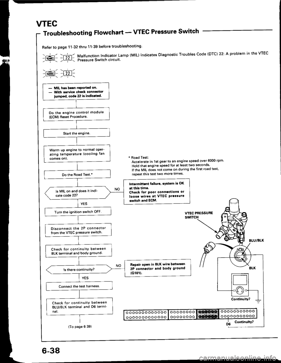
Troubleshooting Flowchart - VTEC Pressure Switch
Refer to page 11-32thru 11-39 beJore troubleshooting'
-.+- -r";-r- Malfunction Indicator Lamp (MlL) indicates Oiagnostic Troubles Code (DTC) 22: A problem in the VTEC- l{{?l- ;l ziz r: pressur€ Switch circuit.
-lr@l- |22 1-
* Road Test:Accolerato in lst gear to an engine speed over 6000 rpm
Hold that engine speed for at least two seconos'
lf the MIL does not come on during the first road test'
reoeat this test two more limes.
- MIL har bagn.oportcd on.- With t.rvic. chack connactor
iump.d, cod€ 22 it indic.t.d.
Do the engine control module(ECM)Reset Procedure.
Warm !p engine to normal oper-
ating temperstur€ (cooling fan
comes on).
Do the Boad T€st.'
Intc.mift.nt failu.o, ry3tom ia OK
at thi. tim..Chack for pool connaction3 ol
loo!. rvirat at VTEC Ptasturo3whch and ECM.
ls MIL on and does it indi'
cate code 22?
Turn lhe ignition switch OFF
Disconnect the 2P connector
lrom the VTEC Pressure switch.
Check Ior continuity between
BLK terminal and body ground.
Rcpair opcn in BLK wit. botwcon
2P connector rnd body ground
tG101l.
Check for continuity between
8LU/8LK terminal and D6 termi'
nal.
(To page 6 39)
Page 101 of 1413
VTEC
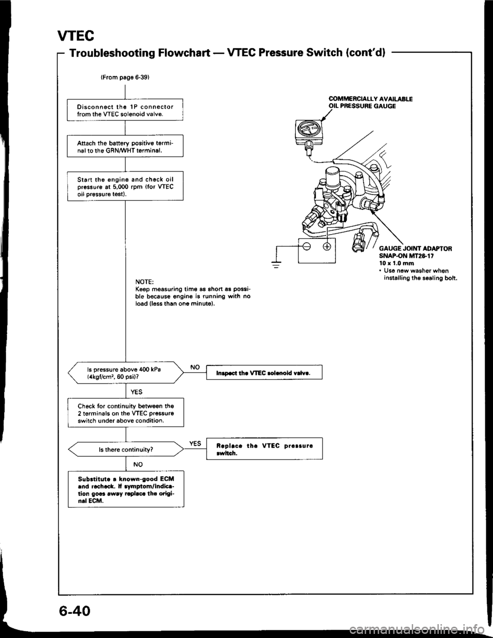
Troubleshooting FlowchartVTEC Pressure Switch (cont'dl
lFrom pag6 6-39)
Disconnsct lhe 1P connectortrom the VTEC sol6noid valve.
Attach the battery positivo torminal to the GRN/WHT terminal.
Start the engine and chgck oilpressure at 5,000 rpm (lor VTECoil pr€ssure test).
ls pressure above 400 kPa(4kgt/cm,, 60 psi)?In.p.ct th. VIEC .olrnoid v.lv..
Check tor continuity betwe6n the2 terminsls on th€ VTEC prsssure
switch !nder above condition.
Sub.titut. . klown-eood ECMand rachack. |f aymplom/indica-tion goaa away rrplaca th. o?igi-n.l ECM.
u
OOMMERCIALLY AVAILABIIOIL PRESSURE GAUGE
GAUGE JOIMf ADAPIORSNAPON MT2S1'10x 1.0 mm. Use new washer wheninstalling th6 soaling bolt.NOTE:Keep moasuring tim6 as shon 6s possi-
ble because engine i5 running with noload lless than ono minuto).
Page 102 of 1413
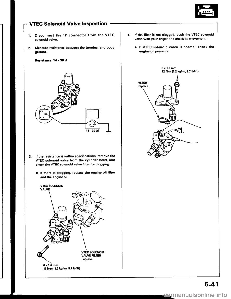
WEC Solenoid Valve Inspection
Disconnect the 1P connector trom the VTEC
solenoid valve.
M€asurs resistance between th€ terminal 8nd body
grouno.
R.3bt!nc!: 1l - 30 O
lf the resistance is within specificstions, romove the
WEC sol€noid valve from the cvlindor hsad, and
check the VTEC solenoid valve filter for clogging.
. lf there is clogging, replacs the engin€ oil filter
and the engine oil.
VTEC SOT.CNOTD
12 tTln 11.2 kg[.m,8.7 lbttt]
6-41
4. lf th6 filter is not clogged, push the VTEC solenoid
valv€ with your finger and check its movement.
. lf VTEC solsnoid valve is normal, check the
engins oil pr€ssure.
6x1.0mm
Page 213 of 1413
![HONDA INTEGRA 1994 4.G Workshop Manual E:I
I if,l.)
l;TYra-"wrrr. Ile llel/nEo II€ TcRNrwHrtlI ,ITwHr^rJl I
c214
ffi
c1
r+lrl2l
trtr
32
o
c112
rft]
IOTBLF------lla lsLx/YEL Ifo lanlr l]l
c111
6
\:-/
lI-FErwHr - l1olGuNlert l-l
cl1
3t
tr HONDA INTEGRA 1994 4.G Workshop Manual E:I
I if,l.)
l;TYra-"wrrr. Ile llel/nEo II€ TcRNrwHrtlI ,ITwHr^rJl I
c214
ffi
c1
r+lrl2l
trtr
32
o
c112
rft]
IOTBLF------lla lsLx/YEL Ifo lanlr l]l
c111
6
\:-/
lI-FErwHr - l1olGuNlert l-l
cl1
3t
tr](/img/13/6067/w960_6067-212.png)
E:I
I if,l.)
l;TYra-"wrrr. Ile llel/nEo II€ TcRNrwHrtlI ,ITwHr^rJl I
c214
ffi
c1
r+lrl2l
trtr
32
o
c112
r'ft]
IOTBLF------lla lsLx/YEL Ifo lanlr l]l
c111
6
\:-/
lI-FErwHr - l1olGuNlert l-l
cl1
3t
tr
c1c117lB18C1 engine)
/ r\
\^y
IETYEL/€Lh---llohED' ----,,
c216
^Jl
FFIN
c221
ffi
ldlcRr/vEr ---l
NOTE: a Different wires with the same color have been given a number suffix
YEL/BLK1 and YEL/BLK, are not the same).
O: Related to Fuel and Emissions System.
a - Connector of male terminals: View from terminal side- Connector of temale terminals: View from wire side
c215
r'fr]
fi'Twtl-rirllrlerrrltlerl-lfr-Twrr - lll
I@ LWHTTREO I
to distinguish them (for example,
(cont'd)
11-21
cl10
ohN/BLK l|/BL!
ALU/YEL
Page 215 of 1413

c119
A
RP
16lwHiffiN----f
l@ lwHrnco' I| 3 laL&YEr IfrlwHrEru ---
ct 20
l8lSBt.nglnrl
ET
l6TciN-6LU-----loliEo/YEi----.
cr20(Bl8Cl .ngln l
F,-f.
\?
l6-ltR,iEit----l@ IiEp/YcL I
cr33
A
.2
|o lhEo/8llJ II-T- --.-.1
NOTE: a Different wires with the same color have been given a numbe. suffix to distinguish them (for example
YEL/BLK1 and YEL/BLK, are not the same).
O: Related to Fuel and Emissions System.a - Connector of male terminals: View from terminal sid6- Connector of female terminals: Viow from wire side
24
ffi
c 123
ffi
l6'lau,-r, ---------l
IO IYEL/8LX I
c121
fr
c3t I
O
tsF
c117
lBl88l 6nginol
EI
//t\t zt
|6-I!EUBLK --'l
lO lhEo' I
c122
ffi
cl16
FI
\2
|@|iaf,-'6trlaltrlaru----1toltEUB'.f----
ct 34
,8.
\^y
f6-IPilK/BLu---lIO IYEUBL( I
11-23
Page 217 of 1413
c4't9
234578e nc
5t6 | -
aALUfYELYEL'
c423
c431lwlthcruit€coniroll
| 'lrl
lslnl
fitr G-Fil------lo ln/Hr/68n Ilo lciN,r/vHr Il-IcRY------l
c44il
riTLF-Iffi14l51617l
lO lGRt/8LU ITitfgruffir-----lktlBrKr--I o lYcL/Gnir Ilao laLx./YEL II "] IYEUBL( Iktlterwirr ---
c431(wlthout
crui!acontrol)
-tttI
t3
l6'TwHr/cnN ----'l
1ol cRN^vHr ----l
c439
rfltrrn
I'VCT,1
lETWrr;eo---ffrlwHr. --
l3l8rK II t lBLx,REo It5 |I 6 GRN/BLX If?-TFEpcFN --
c432
ffi
c444
ffir
trtr]
I6TLK^//Hr -l
L ' l!!g!!r llo lsLkrFED I|;TBLU'BLi l]l
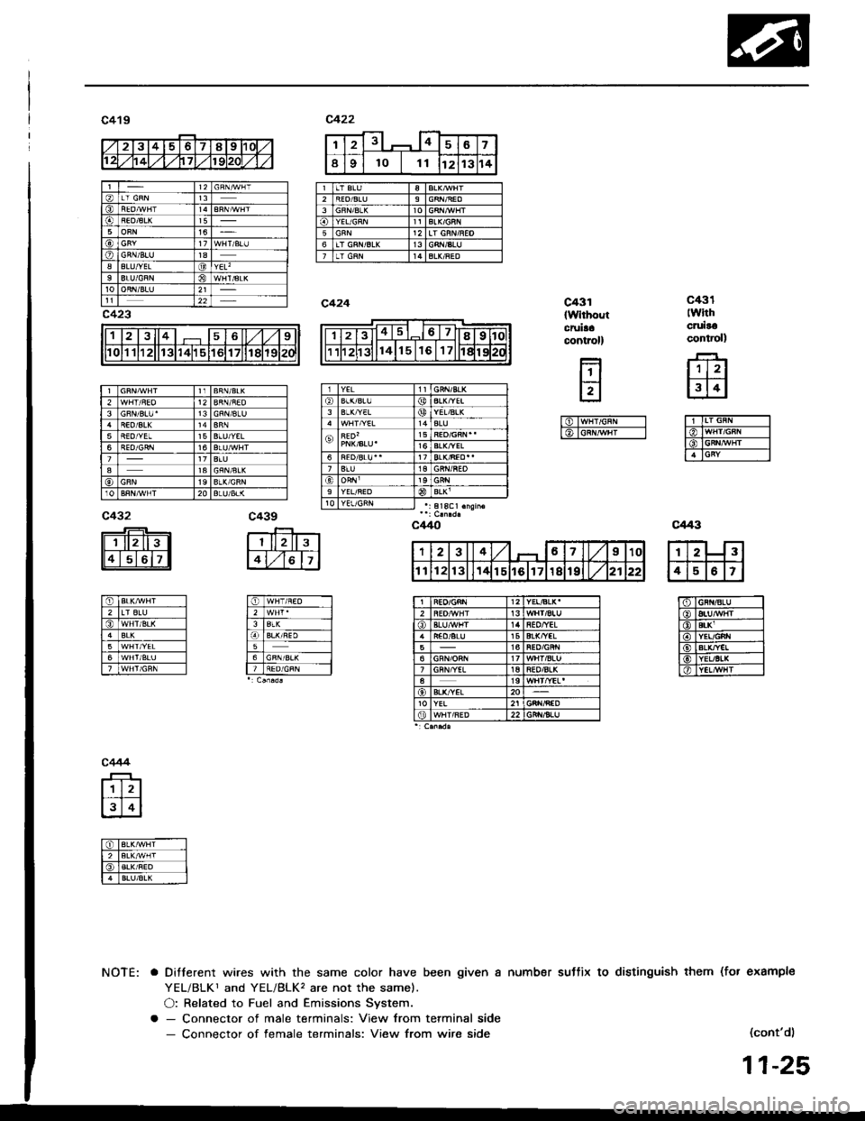
NOTE: a Ditterent wires with the same color have been given a number suttix to distinguish them (fot example
YEL/BLKr and YEL/BLK, are not the samel.
O: Related to Fuel and Emissions System.
a - Connector of male terminals: View from terminal side- Connector of female terminals: View from wire side(cont'd)
11-25
12313
5BLU/YEL6
a1a
20
YEL/BLK'2Ht/aluiEO/YIL15516't7
aBL&"/EL20YEL
Page 219 of 1413
123467
Ir0l1 11121131 114115116
gL&YELBLK/YEL212BLKGFN,YELYEL515
I
6
GFNLT GRII/SL(9GRN/BLII5
REO/6LU28RN/8LK3BLU12BLUf/€LYEL/RED136YEL16BLUYEL/6LKt6
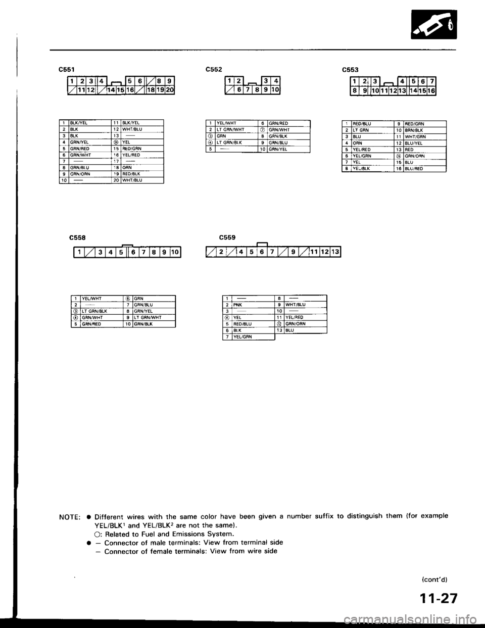
a DiJterent wires with the same color have been given a number sutfix to distinguish them (for example
YEL/BLK1 and YEL/BLK'� are not the same).
O: Related to Fuel and Emissions System.
a - Connector ot male terminals: View from terminal side- Connector of female terminals: View from wire side
{cont'd)
11-27
Page 221 of 1413
c405
fr
ffi
c406
r'tr--Jl
I6TBRN/B,L( -----l
l€, lwHr/uED -__-l
l6TLr BN--- l_l
c408 {ECM-Bl
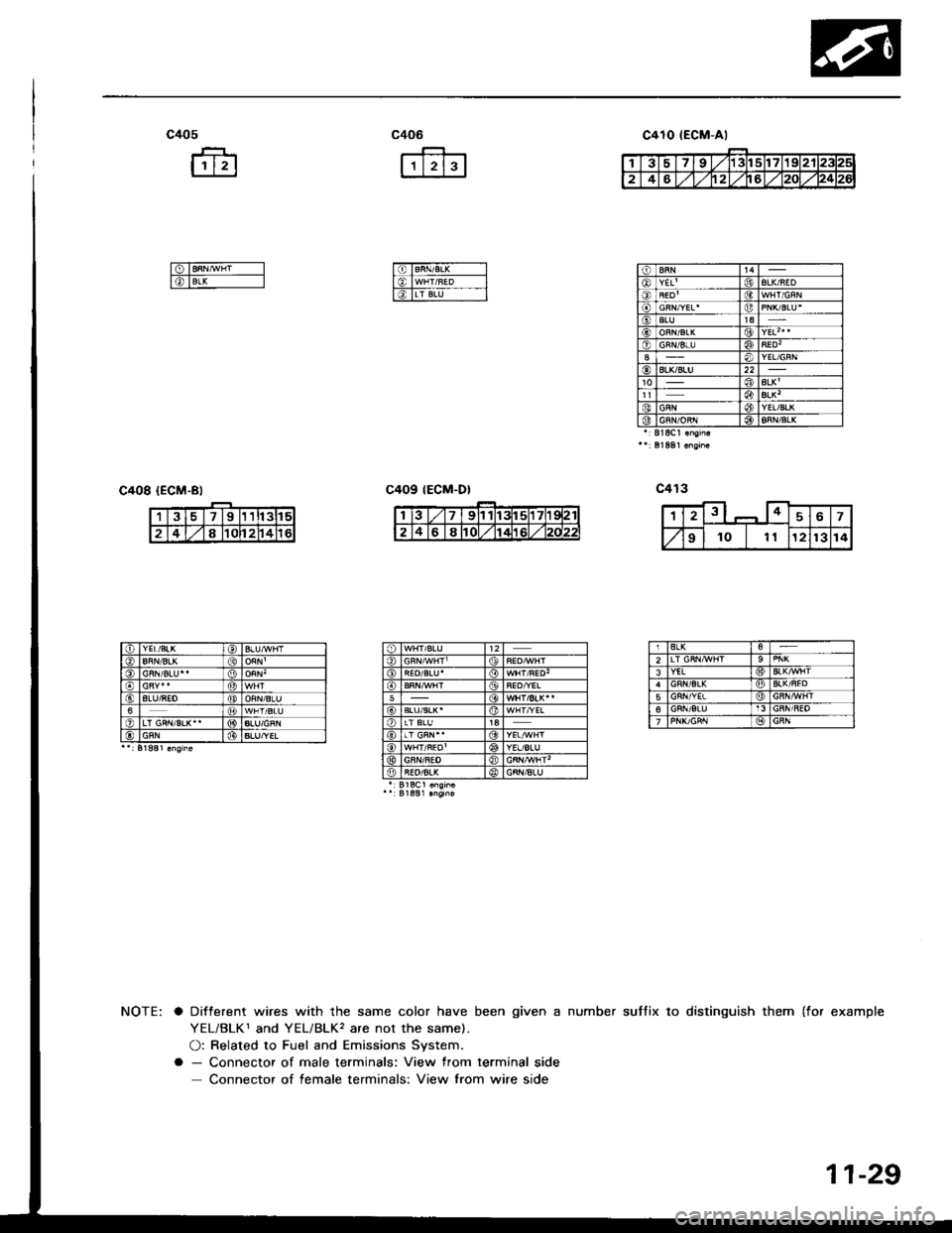
suffix to distinguish them (for examplea Different wires with the same color have been given a number
YEL/BLK1 and YEL/BLK, are not the same).
O: Related to Fuel and Emissions System.
a - Connector of male terminals: View from terminal side
Connector of female terminals: View from wire side
c410 tEGM-Al
tt4YEL'| (jtALK/AED
SLU1aALKt(9YEL| 0o)
ALK'ALK'YEL/BLKGRN/oRr l@BLK
391t3tl5
2481Cl24
IALU/REO6
ALU/YEL
BLK2YEL
56
11-29