connector or terminal HONDA INTEGRA 1994 4.G User Guide
[x] Cancel search | Manufacturer: HONDA, Model Year: 1994, Model line: INTEGRA, Model: HONDA INTEGRA 1994 4.GPages: 1413, PDF Size: 37.94 MB
Page 223 of 1413
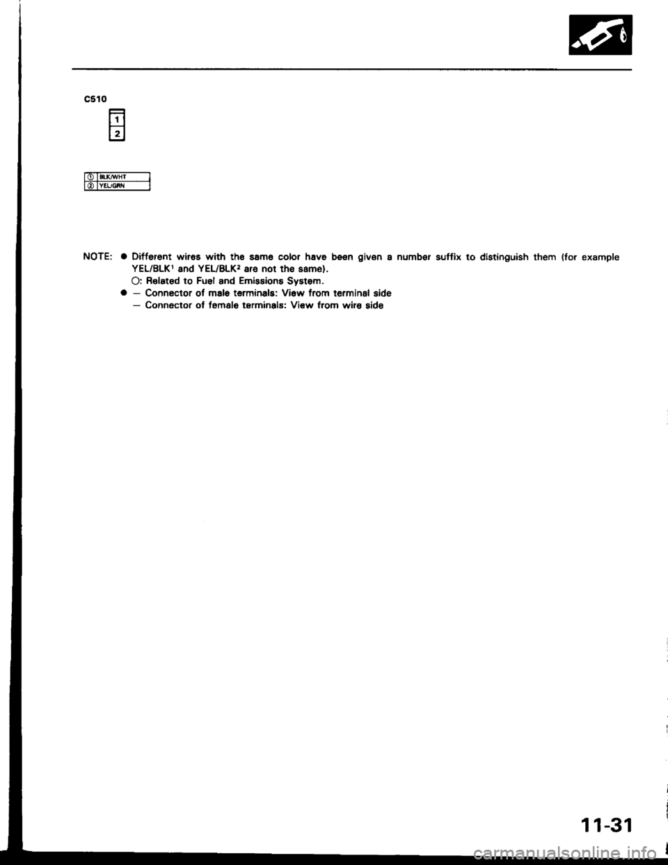
c510
NOTE: a Ditferent wiros with tho samo color hava been given a numb€r sutfix to distinguish them {for example
YEL/BLKI and YEL/BLK, are not th€ same).
O: R€lated to Fuel and Emissions Systom.
a - Connoctor ol malo tarminals: Vi6w from terminal side- Connector ol f6msl€ tarminals: Vi€w from wire sid€
11-31
Page 234 of 1413
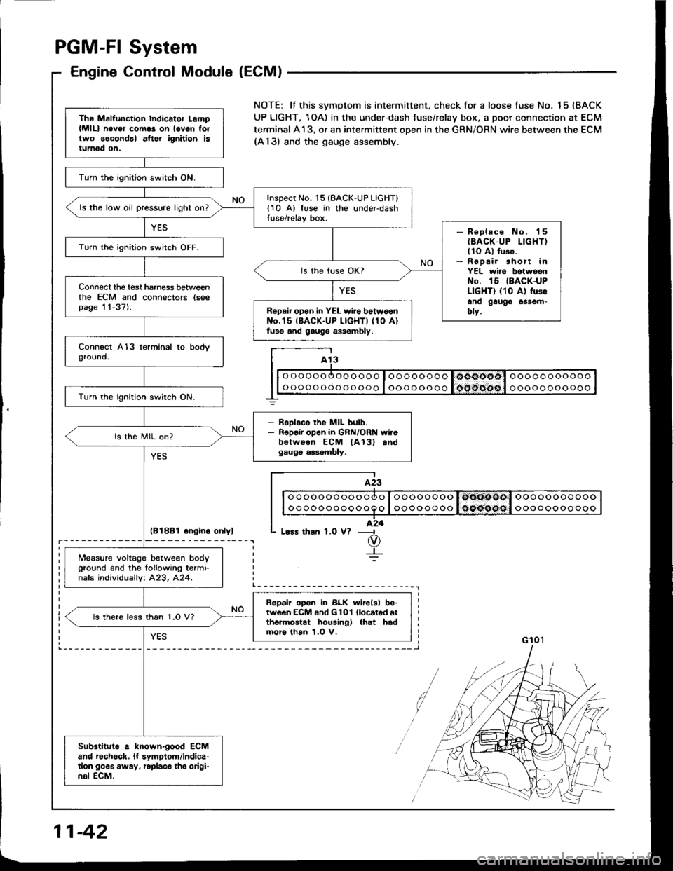
PGM-FI System
Engine Control Module (ECM)
lB18B1 ongino onlyl
The Malfunction Indicator Lamp(MlL) n6v6. com6s on lovon follwo socondal aftor ignition istumed on.
lurn the ignition switch ON.
Inspect No. 15 {BACK-UP LIGHT}l1O A) luse in the underdashtuse/relay box.ls the low oil pressure light on?
- R€placo No. 'l5
IBACK-UP LIGHT)llo Al fuso.- Ropair short inYEL wiro botwoonNo. 15 (BACK-UP
LIGHT) {10 A) fusoano gauge 6$om-blv.
Turn lhe ignition switch OFF.
ls the fuse OK?
Connecl the test harness betweenthe ECM and connectors (seepag€ 11-37).Repair opon in YEL wiio botw6onNo.'15 IBACK-UP LIGHTI 110 A)luso and gaug6 assombly.
Turn the ignition switch ON.
- RsDlaco tho MIL bulb.- Ropair opon in GRN/ORN wi.ebetwoen ECM {A13} andgaug€ a$6mbly.
ls the MIL on?
Measure voltage between body
Oround and the tollowing termi-nafs individuallv: 423, 424.
Ropah op6n in BLK wirolsl bo-tw6en ECM and GlOl llocatod atthormostat housing) that hadmoro than 1.0 V.
ls there less than 1.O V?
Substituto a known-good ECMand rochgck, lf symptom/indica-tion go€s away, roplaco tho origi-nal ECM.
NOTE: lf this svmptom is intermittent. check for a loose fuse No. 15 (BACK
UP LIGHT, 1OA) in the under-dash Juse/relay box, a poor connection at ECM
terminal A13, or an intermittent open in the GRN/ORN wire between the ECM(A13) and the gauge assembly.
I A13
I| | o oooo oooooooo I oooo oooo I ooooool ooooooooooo I
G 10'�l
11-42
Page 235 of 1413
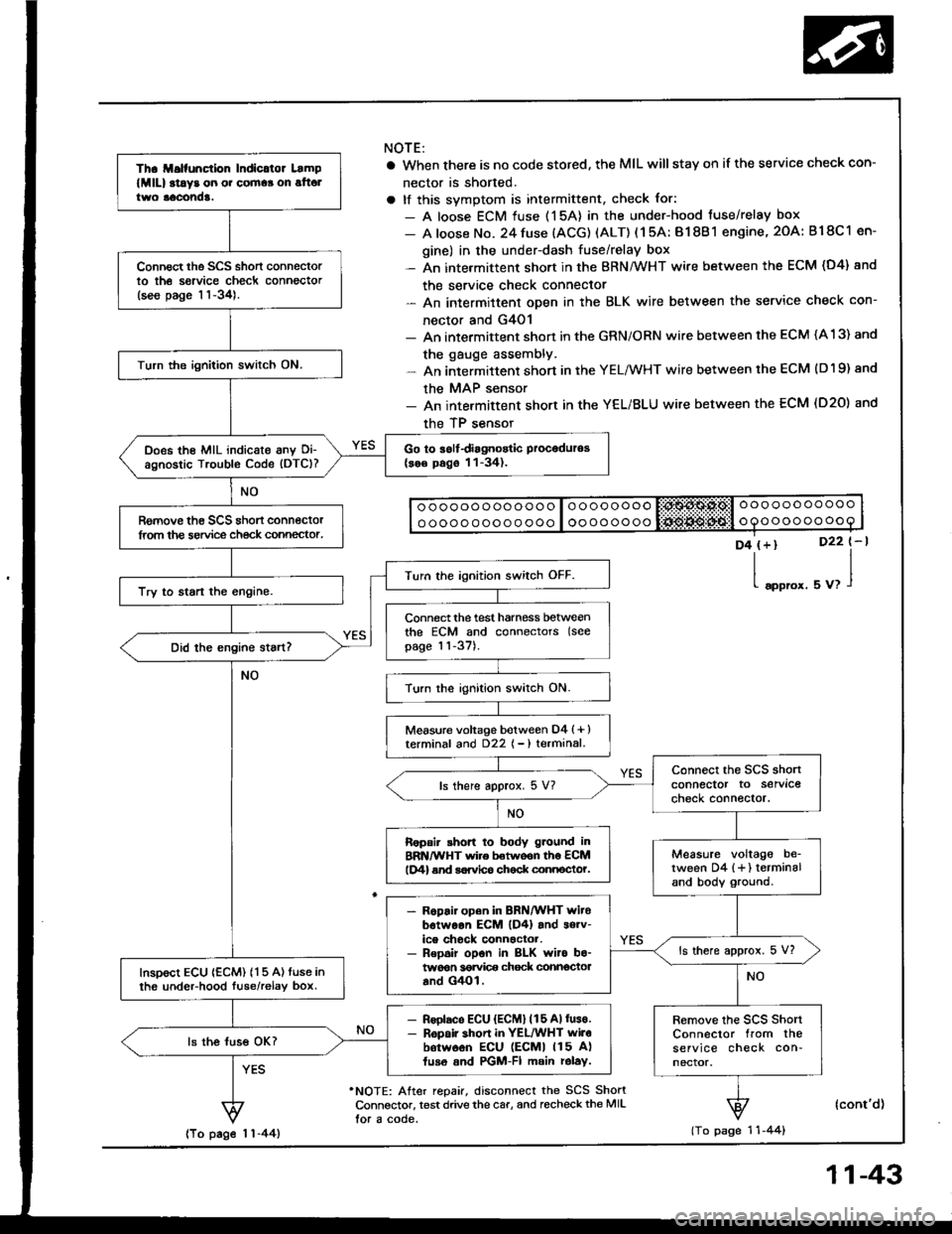
Th. ll.lfunction Indicltor Lamp
lMlll at!y3 on o. cornaa on alt6ltwo aacond!.
Connect the SCS short connectorto th6 sorvice check connector(see page 11-34).
Turn the ignition switch ON.
Go to iolfdiagnostic Proceduros(se€ pago 11-34).Does the MIL indicate anv Oi-agnostic Trouble Code (DTC)?
Romove th€ SCS shon connectorlrom the service ch€ck connector.
Turn the ignition switch OFF.
Try to start the engine.
Connect the test harness betweenthe ECM and connectors (see
page 11-37).
Turn the ignition switch ON.
Measure voltage botween D4 (+ )terminal and D22 { - ) terminal.
connect the SCS shonconnector to servlcecheck connector.ls there approx. 5 V?
Ropair shon to body g.ound inBRN/WHT wire betwoon th6 ECMlD4) end sorvlco chock connocto?.Measure voltage be_tween D4 {+} terminaland body ground.
- R6pair open in BRN/WHT witobotwoon EcM lD4) and s6rv-ice chock connactor.- Repoir opon in BLK wiro bo-twoon 36rvi@ chock connectoaand G4Ol.
ls there approx. 5 V?
InsDoct ECU {ECM) 115 A) tuse inth6 undeFhood luse/relav box.
- Rsolaco ECU {ECM} (15 Allus€.- R6pair shon in YEL/WHT wilobotw6on ECU lEcMl 115 A)fuso and PGM-FI main rolay.
Remove the scs shortConnector from theservice check con-nector.
ls the luss OK?
NOTE:
a When there is no code stored, the MIL willstay on if the service check con-
nector is shorted.
a tf this svmotom is intermittent, check for:
- A loose ECM fuse (15A) in the under-hood tuse/relay box
- A loose No. 24 fuse (ACG) (ALT) ( 1 5A: B1 8B 1 engine, 2OA: B18C 1 en-
gine) in the under-dash fuse/relay box- An intermittent short in the BRN/WHT wire between the ECM (D4) and
the service check connector- An intermittent oDen in the BLK wire between the service check con-
nector and G4O1- An intermittent shon in the GRN/ORN wire between the ECM (A 13) and
the gauge assembly.- An intermittent short in the YELMHT wire between the ECM (D19) and
the MAP sensor- An intermittent short in the YEL/BLU wire between the ECM (D20) and
the TP sensor
o ooooo ooo ooo o loooooooo liii:$A$.Ps,l o oo ooo ooooo
o oooo ooo o o ooo I oooooooooooooooooo
D4 (+)
l"oo,o'.
D22 t-l
uu,l
'NOTE: After repair, disconnect the SCS ShortConnsctor, test drive the car, and recheckthe MIL
lor a code.
(cont'd)
(To page 1 'l -44)lTo page 1 1-44)
11-43
Page 240 of 1413
YES
PGM-FI
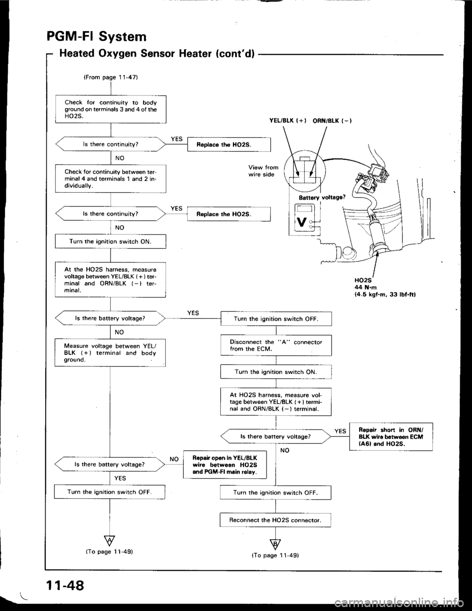
Heated
11-471
System
Oxygen Sensor Heater (cont'd)
YEL/BLK I+I ORI{/BLK (-I
wire side
HO2S44 N.m{4.5 kgt.m, 33 lbf.ft}
Check for continuity to bodyground on terminals 3 and 4of theHO2S.
Check for continuity between terminal4 and terminals 1 and 2 in-dividually.
Turn the ignition switch ON.
At the HO2S harness. measurevoltage between YEL/BLK 1f lteFminal and ORN/BLK l-) ter-mrnal.
Turn the ignition switch OFF.
Disconnect the "A" connectorfrom the ECM.Measure voltage between YEL/BLK l+) terminal and bodyground.
Turn the ignition switch ON.
At HO25 harness, measure vol-tage between YEL/8LK (+) termi-nal and ORN/BLK {-) terminal.
RoDair short in ORN/BLK wir6 b6tw6on ECM(A6l and HO2S.ls there baftery voltage?
Ropai. opon in YEL/BLKwire botwoan HO2S.nd PGM-FI main relav.
Turn the ignition switch OFF.Turn the ignition switch OFF.
11-48
{To page 11-49){To page 11-49}
Page 241 of 1413
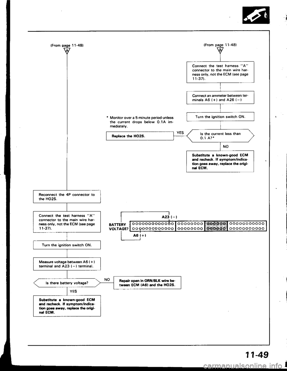
* Monitor over a 5 minute Deriod unl6ssthe current drops below O.1A im-mediatelv.
BATTERYVOLTAGE?
L-E;
o ooooooooo ooo I ooooo oooooooooooooo
oo Qoooooooooo I oooooo ooooooooooooo
Connect the test harness "A"
connector to the main wire harness only, not the ECM (see page
1 1-371.
Connect an ammetet between ter-minals A6 {+ ) and 426 (- )
Turn the ignition switch ON.
ls the current less than0.1 A?.
Subrtitulo s known-good ECM.nd r.ch6ck. lf symptom/indica-tion goes away. roplaco tho origi-n.l ECM.
Connoct the test harn€ss "A"
connector to the main wire har-n6ss only. not th€ €CM {seo page't't-37).
Turn the ignition switch ON.
Measwe vohage bstween A6 {+ }tg.minal and A23 {-)terminal.
Ropsii op6n in ORN/BLK wiro bo-tw..n ECM {A6l and tho HO2S.
Subrtiluto s known{ood ECMlnd Echock. ll .ympiom/indic{-tirn god !way, '.pLc! f|e origl-h.l ECM.
11-49
Page 245 of 1413
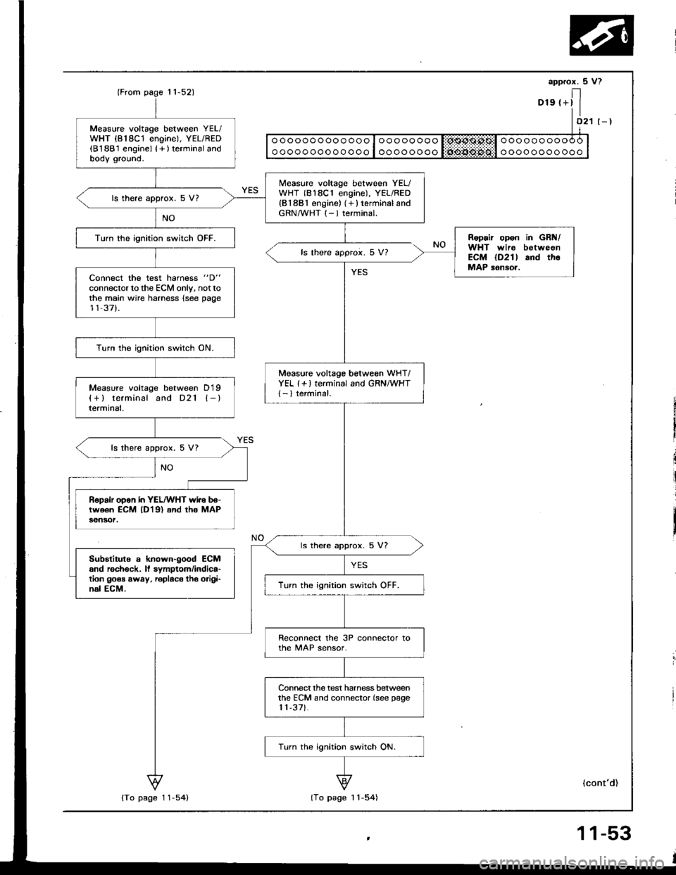
Measure voltage between YEL/WHT {818C1 engine), YEL/RED(B188'1 engine) {+ ) terminal andbodv ground.
Measure voltage between YEL/WHT (818C1 engine), YEL/RED{B1881 engine) (+ } terminal andGRN/WHT (- ) terminal.
ls there approx. 5 V?
Repair opon in GRN/WHT wir6 botweonECM lD2l l and thoMAP sonsor,
Turn the ionition switch OFF.
ls there approi. 5 V?
Connect the test harness "D"
connector to the ECM only, nottothe main wire harness {see page11,37).
Turn the ignition switch ON.
Measure voltage betweon wHT/YEL (+ ) terminal and GRN/WHT{- } terminal.Measure voltage between D19{+} terminal and D21 {-}termrnat,
ls there approx. 5 V?
Bepair open in YEL/WHT wi.e be-tw€6n ECM lD19) and tho MAPaon30t.
ls there approx. 5 V?
Substitule s known-good ECMand rechock. ll symptom/indica'tion goes away, replac€ tho oiigi'nal ECM.Turn the ignition switch OFF.
Reconnecl the 3P connector tothe MAP sensor.
Connect the test harness betweenthe ECM and connector (see page1 1-371.
Turn the ignition switch ON.
11,52)
{To page 11-54}lTo page I l-54)
(cont'd)
Page 246 of 1413
PGM-FI System
Manifold Absolute Pressure
lFrom page 11-53)
{MAPI Sensor (cont'd)
(From paqe 1 1-53)
NO
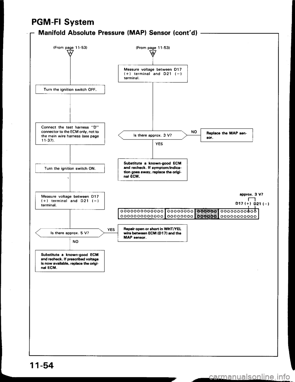
M6asure voltage between D17{+) terminal and 021 (-}terminal.
ls there approx. 3 V?
Substituto 6 known{ood ECM.nd rach.ck. It symptom/indica-tion gooa away, Eplaco tho orlgi-nrl €CM.
Turn the ignition switch OFF.
Connect the test harness "D"
connector to the ECM only. not tothe main wire harness lsee page11-37).
Turn the ignition switch ON.
Measure voltage botwson Dl7(+) terminal and D21 {-}terminal.
R.p.lr opon or ahort in WHT|rELwi?o botw.on ECM {O17) and thoMAP senso..ls there approx. 5 V?
Substitute a known{ood ECMand rochsck. It prdcribed voltrgob now availablo, rophce trie origi-nal ECM.
approx. 3 v?
-D17 til D21 (-l
ooooooooooooo I oooooooo l l5oiE€tdl ooooooo
o oooo oooooooo ! ooooooooooooooooooo
11-54
'.---.-'
Page 250 of 1413
ECT SENSOR
GRN/BLU {-}
Turn the ignition switch ON.
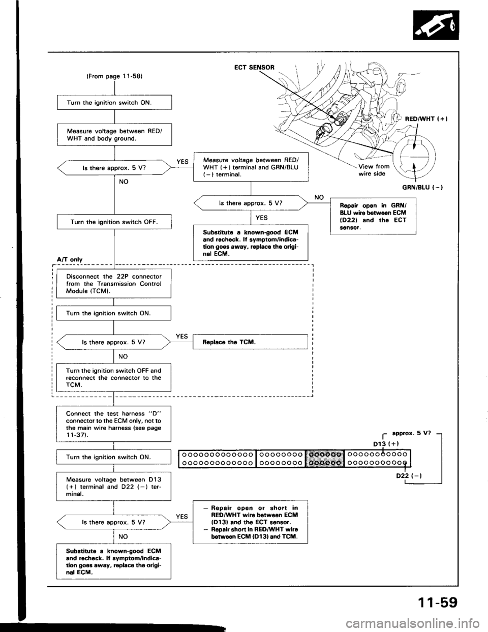
Measure voltage betweon RED/WHT and body ground.
Measure voltage between RED/WHT {+}terminal and GRN/8LU(- ) terminal.ls there approx. 5 V?
ls there approx. 5 V?Ropai. opon in GRN/BLU wiro botwoon ECM(D221 and tho ECT36n3('r.Turn the ignition switch OFF.
Sub3tituto a known-good €CMand rochock. lf 3ymptom/indica-tion go6s away, roplaco the odgi-nal ECM.
Oisconnect the 22P connectortrom the Transmission ControlModule (TCM).
Turn the ignition switch ON.
ls there approx. 5 V7
Turn the ignition switch OFF andreconnect the connector to theTCM.
Connect the test harn€ss "D"
connector to the ECM only. not tothe main wire harness {see page11-37).
Turn the ignition switch ON.
Measure voltage between D13(+) terminal and D22 (-l ter-mlnal.
Repair opoa or shon inREO/WHT wiro botwoen ECMlDl3l and th6 ECT sonsor.R6pair shon in REO/WHT YYi..b6tw66n ECM {D131and TCM.
ls the.e approx. 5 V?
Substiluto a known-good ECMand rochock. ll lymptom/indica-tion goea 6wsy, replaco tho o.igi-n6l ECM,
A/T only
I
_i
11-59
Page 251 of 1413
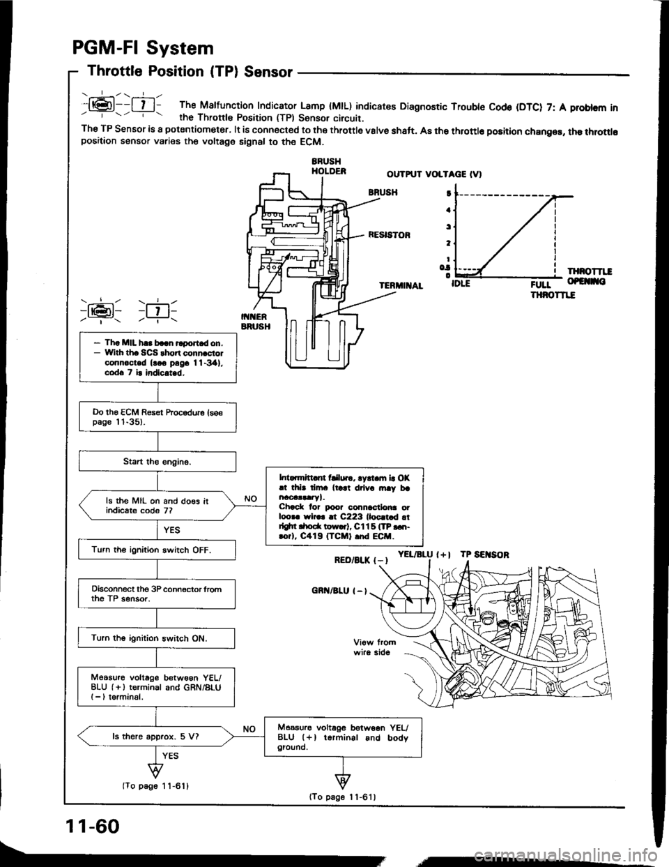
.:-\.-----ll@l--l t l- The Malfunction Indicator Lamp (MtL) indicatee Diagnostic Trouble Cod€ (DTC) 7: A problcm inrhe Thronle Position (TPl Sonsor circuit.The TP Sensor is a potsntiometer, lt is connected to the throttle valve shaft. A8 the throttlo position chan96, the throttlopositaon sensor varies the voltage signal to the ECM.
BBUSHHOLDER
PGM-FI System
Throttle Position (TPl Sensor
OUTPUT VOLTAGE IV)
BNUSH
RESISTOF
IXNOTTII
TERMIIIAL;0rr- of€ no
THNOTTIE
YEL/aLU l+l TP SEITSOR
I
a
t
t
Io.|o
RED/BLK {-I
cnn/BLu I - l
)ran1 )ril-Y- -?..
- Th. MIL h.. baln rlport d on.- With th. SCS thort conn.ciolconn.c-ted (rco pngc 11-341.codo 7 i. indlc.t d.
Do the ECM Reset hocedure (se€page l 'l-35).
l. ..mrtt nt fClur., lyrt m la OX.t thb dm. ll.at drlv. rn.y brncoaataryl.Chack lor poo? connactlo|ra otloora wlr.r !t C223 lloc.t d !tdgtn drod( tow..t, Cl15 ITP ...t-rorl, C419 (TCMI .nd ECM.
ls the MIL on and do€s itindicats codo 7?
Turn th€ ignition switch OFF.
Disconnect tho 3P connector lromth€ TP sensor.
Turn the ignition switch ON.
Meosu.o voltage betwoon YEL/BLU (i ) terminal and GRN/BLUI -, torminal.
Measurs voltagG betw66n YEUBLU (+l terminal and bodygiound.ls there approx. 5 V?
(To page 1 1-611
11-60
(To page 1 1-6'l )
,,,----
Page 252 of 1413
(From1 1-60){From
A/T only
Turn the ignition switch OFF.
Connect the test harness betweenthe ECM and connectors (seepage 11-37l-.
Turn the ignilion switch ON.
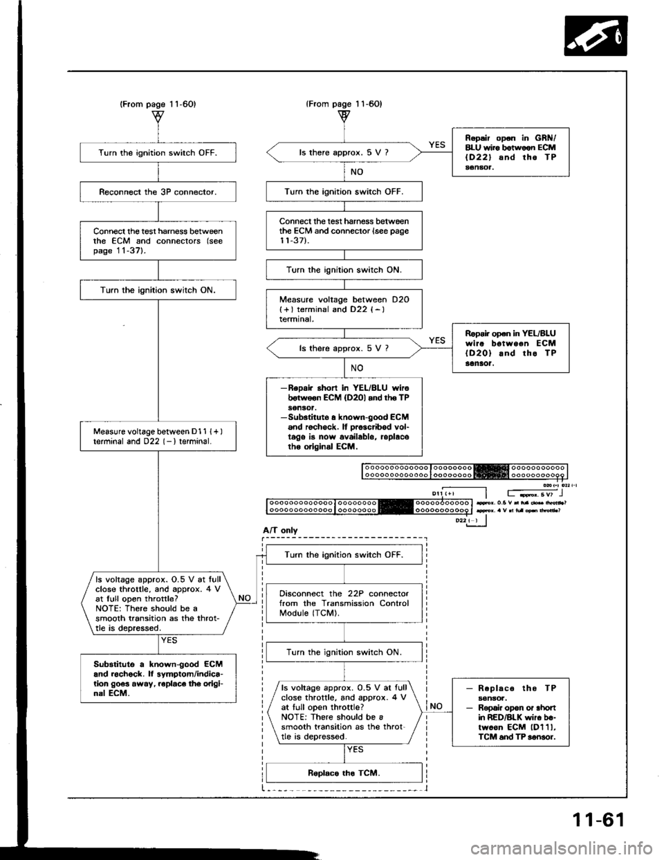
Measure voltage between D1 1 {+ )terminal and 022 (- I terminal.
Turn the ignition switch OFF.
ls voltage approx. O.5 V at lullclose throtlle. and approx. 4 vat full open throttle?NOTE: There should be asmooth transition as the throt-tle is depressed.
Disconnect the 22P connectorfrom the Transmission ControlModule (TCM).
lurn the ignition switch ON.
Substitute a known-good ECMand roch6ck. ll symptom/indica-tion 9063 away, roplaco th6 origi-nal ECM.- Replaco tho TPaonsoa,- Repai. opon or ahonin RED/BLK wir. b€-twoon ECM lDl1l,TCM 6nd TP sonsor.
ls voltage approx. 0.5 V ar fullclose throttle, and approx. 4 Vat tull open throttle?NOTE: There should be asmooth transition as the throt'tle is deprossod.
page 1 1-60)
Repsir op.n in GRN/8LU wii6 botwoon ECMlD22l snd tho TPaenaot.
ls there approx. 5 V ?
Turn the ignition switch OFF.
Connect the test hamess betweenthe ECM and connector {see page11-37).
Turn the ignition switch ON.
Measure voltage between D2O{+) terminsl and D22 {-}termtnal,
Ropoi. open in YEL/BLUwire bgtween ECM{D20} and rho TP30naot.
ls there approx. 5 V 7
-ReDai. ahort in YEL/BLU wiroborwoon ECM (D2Ol and tho TPson30t.-Sub3tituto a known-good ECM6nd rochock. It prcacribod vol-t6go is now availablo, roplacoth6 original ECM.
Fr. o.5 v n tua .b drdn ?
11-61