connector or terminal HONDA INTEGRA 1994 4.G Owner's Guide
[x] Cancel search | Manufacturer: HONDA, Model Year: 1994, Model line: INTEGRA, Model: HONDA INTEGRA 1994 4.GPages: 1413, PDF Size: 37.94 MB
Page 443 of 1413
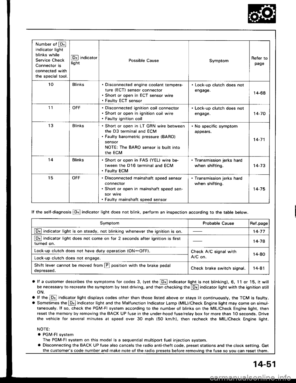
Number of @indicator light
blinks while
Service Check
Connector is
connected with
the special tool.
@ indicator
lightPossible CauseSymptomRefer to
page
'loBlinksDisconnected engine coolant tempera-
rure (ECT) sensor connector
Short or open in ECT sensor wire
Faulty ECT sensor
Lock-up clutch does not
engage.14-68
1lOFFDisconnected ignition coil connector
Short or open in ignition coil wire
Faulty ignition coil
. Lock-up clutch does not
engage.'t 4-7 0
13Blinks. Shon or open in LT GRN wire between
the D3 terminal and ECM. Faulty barometric pressure {BARO)
sensor
NOTE: The BARO sensor is built into
the ECM
. No specific symptom
appears.
14-7 1
14Blinks. Short of open in FAS {YEL} wire be-
tween the D16 terminal and ECM. Faulty ECM
. Transmission jerks hard
when shitting.
't5OFFDisconnected mainshaft speed sensor
connecror
Short or open in mainshaft speed sen-
sor wire
Faulty mainshaft speed sensor
. Transmission jerks hard
when shifting.
14-75
SymptomProbable CauseRet.page
LQ! indicator light is on steady, not blinking whenever the ignition is on.14-77
[Q3] indicator light does not come on for 2 seconds after ignition is first
turned on.14-78
Lock-up clutch does not have duty operation (ON-OFFI.Check A/C signal with
A/C on.14-80Lock-up clutch does not engage.
Shitt leve. cannot be moved lrom @ position with the brake pedal
depressed.Check brake switch signal,14-41
It the self-diagnosis LQ4 indicator light does not blink, perform an inspection according to the table below.
a lf a customer describes the symptoms for codes 3, (yet the LQ! indicator light is not blinkingl, 6, 1 1 or 15, it will
be necessa.y to recreate the symptom by test driving. and then checking the @ indicator light with the ignition still
oN.
e lt ttre @ indicator light displays codes olher than those listed above or stays lit continuously, the TCM is faulty.. Sometimes the Lqd indicator light and the Malfunction Indicator Lamp (MlL)/Check Engine light may come on simul-taneously. lf so, check the PGM-Fl system according to the numbe. of blinks on the MIL/Check Engine light. thenreset the memory by removing the BACK UP fuse in the unde.-hood fuse/relay box for more than 1O seconds. Drive
the vehicle for several minutes at speed over 30 mph (5O km/h), then recheck the MIL/Check Engine light.
NOTE:
. PGM-FI system
The PGM-Fl system on this model is a sequential multiport fuel injection system.a Disconnecting the BACK UP luse also cancels the radio anti-theft code. preset stations and the clock setting. Get
the fuse so vou can reset them.the customer's code number and make note ot the radio
14-51
Page 444 of 1413
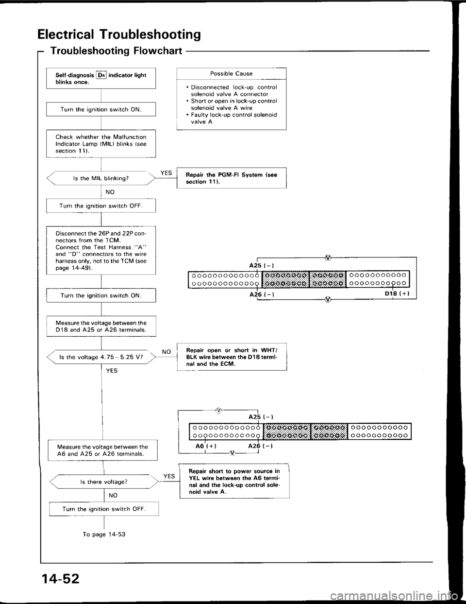
Electrical Troubleshooting
Troubleshooting Flowchart
ls the MIL blinking?
fs the voftage 4.75 5.25 V?
Possible Cause
. Disconnected lock-up controlsolenoad valve A connector. Short or open in lock-up controlsolenoid valve A wire. Faulty lock-up control solenoid
NO
YES
Repair open or shorl in WHT/BLK wir€ botwe€n th€ D18 termi-nal and the ECM.
(-)
| | o " q " " o o o o o o o q litigse.*grq$:,1:d:sd:siia:l " "" o " " o o oo " I
I ro'r+ r rz6 r-tL--- l /trtr-- l
ls there voltage?
NO
ooooooooooo
oooooooo9oo
oooooooooooo
oooooooooooo
A25
Turn the ignition switch ON.
Check whether the MalfunctionIndicator Lamp (MlL) blinks (see
section I 1).
Repair the PGM-FI System (see
section 1 l ).
Turn the ignition switch OFF.
Disconnect the 26P and 22P con-nectors from the TCM.Connect the Test Harness "A"
and "D" connectors to the wireharness only, not to the TCM {seepage 14-49).
Turn the ignition switch ON.
Measure the voltage between theD18 and A25 or 426 terminals.
Measure the voltage between the46 and A25 or A26 terminals-
Repail short to power sourco inYEL wi.e between the A6 termi-nal and the lock-up control sole-noid valve A.
Turn the ignition switch OFF.
To page 14'53
14-52
Page 445 of 1413
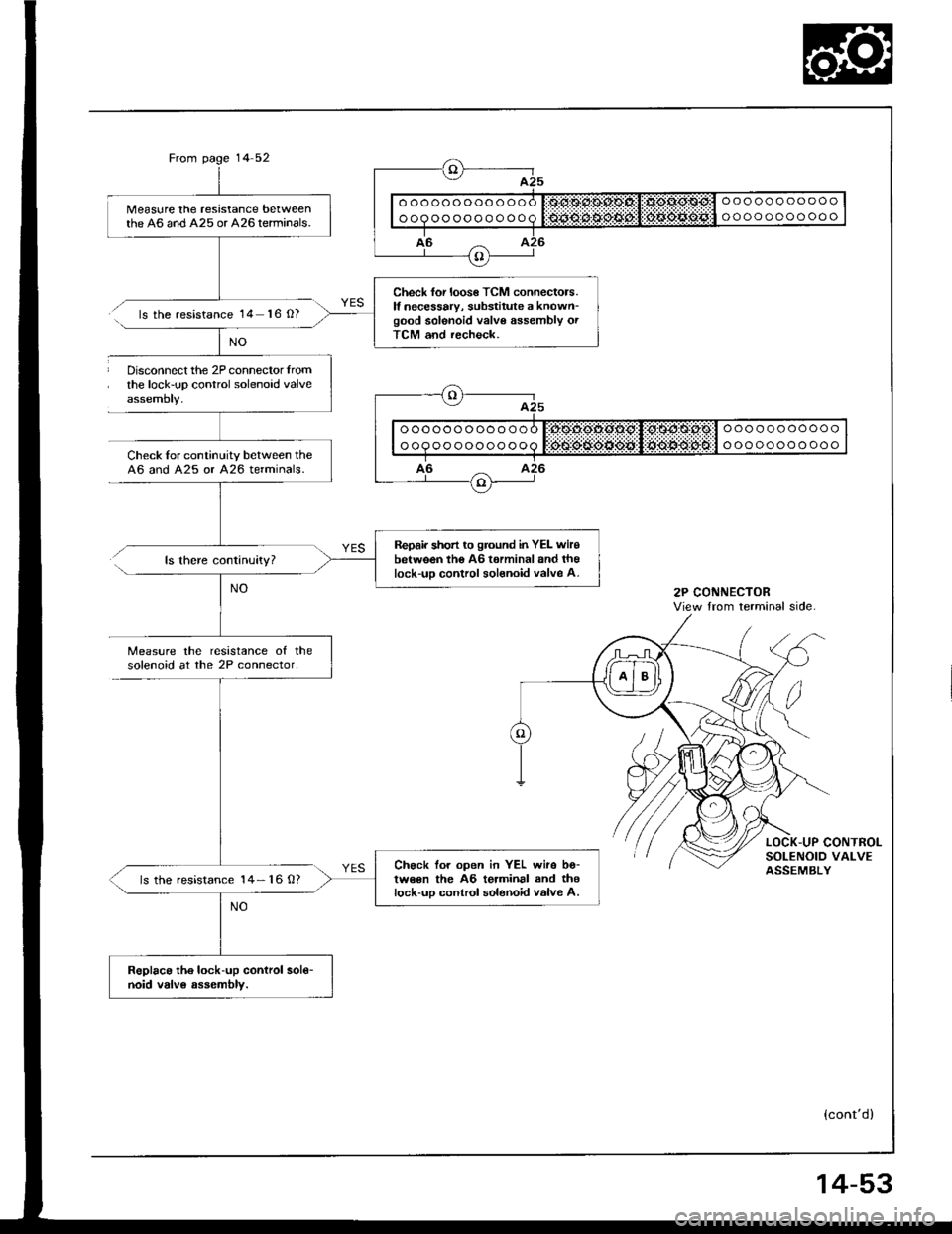
Me6sure the resistance betweenthe 46 and A25 or A26terminals.
Check for loos€ TCM connectors.It necessary, substitute a known_good solenoid valve assembly orTCM and recheck.
Repair short to ground in YEL wirobetween tho AG t€rminal and th€lock-uo control solsnoid valve A.
Ch€ck tor open in YEL wire bo-tween the A6 terminal and thelock-uD control solenoid valve A.ls the resistance 14- 16 0?
RoDlaca th6 lock-up control sol€-noid valv6 assembly.
Disconnect the 2P connector lromthe lock-up control solenoid valve
Check Ior continuitv between the46 and A25 or 426 terminals.
ls the resistance 14 16 O?
ls there continuity?
Measure lhe resistance of thesolenoid at the 2P connector.
{cont'd}
View lrom terminal side
14-53
Page 447 of 1413
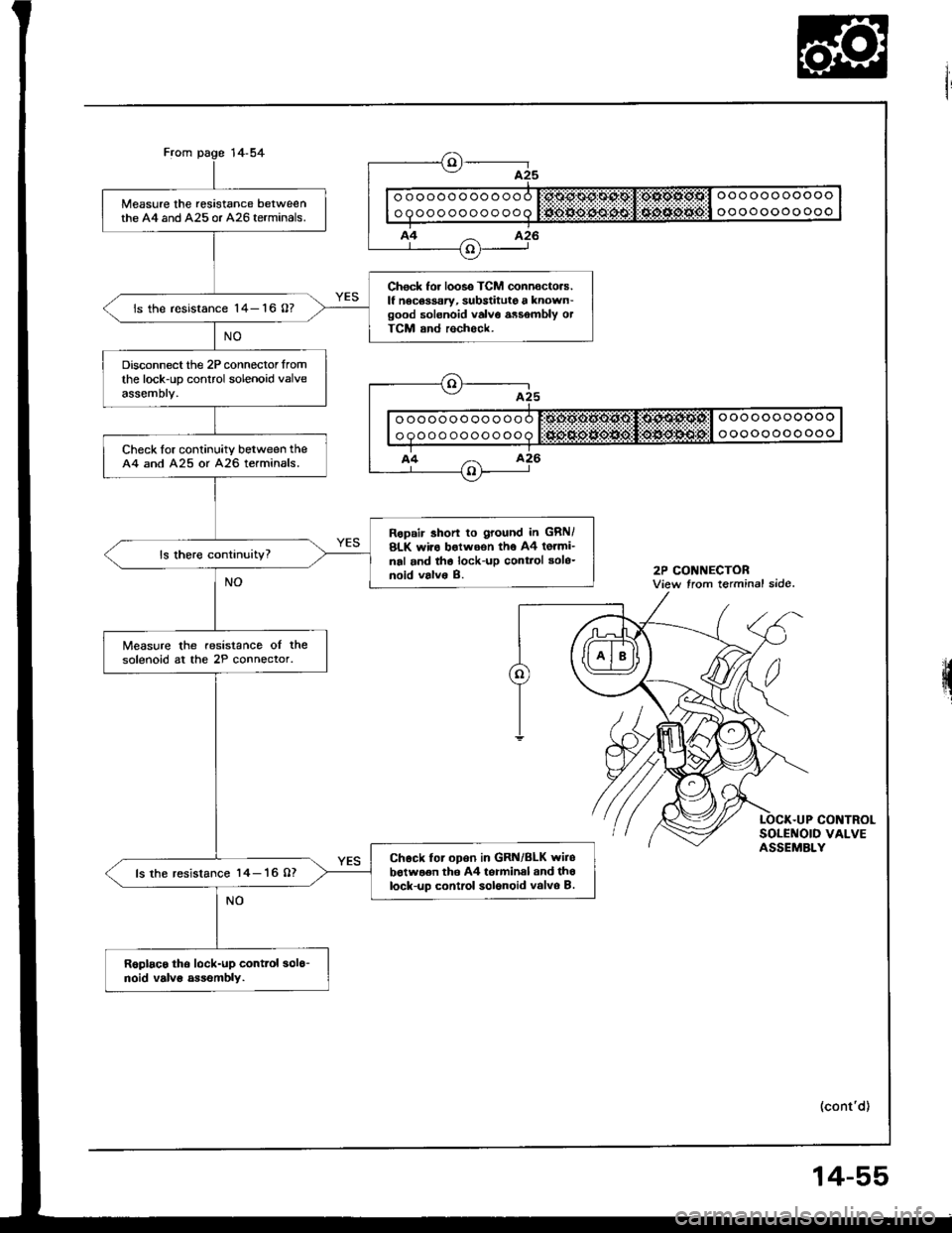
Measure the resistance betweenthe A4 and A25 or A26 terminals.
Check for looso TCM connocto.s.lf nocoasary, substitute a known-good solenoid valvo assombly otTCM and rochock.
is the resistance 14- 16 0?
Disconnect the 2P connector fromthe lock-up control solenoid valveassemory,
Check lor continuitv between theA4 and A25 or A26 terminals.
Ropair 3horl to Itound in GRN/BLK wir6 botwoon tho 44 totmi-nal and th6 lock-up cont.ol solo-noid valv6 B.
Measure the resistance ol thesolenoid at the 2P connector.
Chock lor opon in GRN/BLK wiiobotwaen tho A4 torminal and th6lock-up contrcl solonoid valvo B.ls the resistance 14- 16 07
R6Dlaco tho lock-up conttol 3016-noid valvs assembly.
2P CONNECTORView trom terminal side.
q
.UP CONTROLSOLENOID VALVEASSEMBLY
(cont'd)
14-55
Page 449 of 1413
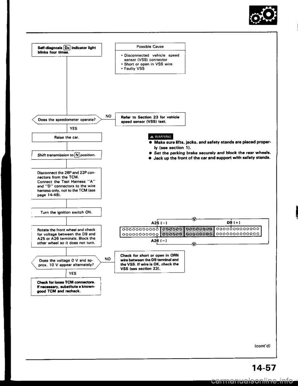
S. d.gno.b lql indic.to. lightbllnkr tour tlm...
R.lor to Soctlon 23 for vohiclerpood lonsoi {vSSl to!t.
Shift t.nsmisiion to A position.
Ch6ck to. shoft or opon in OFilwlro b€twoen tho .)9 t6tminsl andrho VSS. lf wiro is OK, ch€ck thoVSS lsoo soction 231.
Doss lhe voltage O V and ap-p.ox. 10 V appe.r alternately?
Ch.d( tor loo.. TCM co.!n.cto.r.ll nacaaalay, lubrtituta ! known_geod TCM and t chock.
Possible Caus6
. Disconnectsd vehicle speedsensor {VSS} connector. Short or open in VSS wire. Faulty VSS
Disconn6ct the 26Pand 22P con-n.ctors trom th€ TCM.Connect ths Tgst Harnoas "A"
8nd "O" connectors to tho wireharnsss only, not to the TCM (see
page 1+49).
Turn the ignilion switch ON.
a Mak€ sure lifts,lacks, and safety stands aro placod plopor-
ly {see Eaclion 1}.
a S6t th6 parking brake eecurely and block tho tear wh6ol3'
a Jack up tho f.ont ot tho car and rupport whh sstoty standa.
(cont'd)
Rotat€ th€ tront wh6ol and chsckfo. volt6g€ botwean the D9 andA25 o. A26 terminals. Block theother whaol 30 it do€s not turn.
14-57
Page 450 of 1413
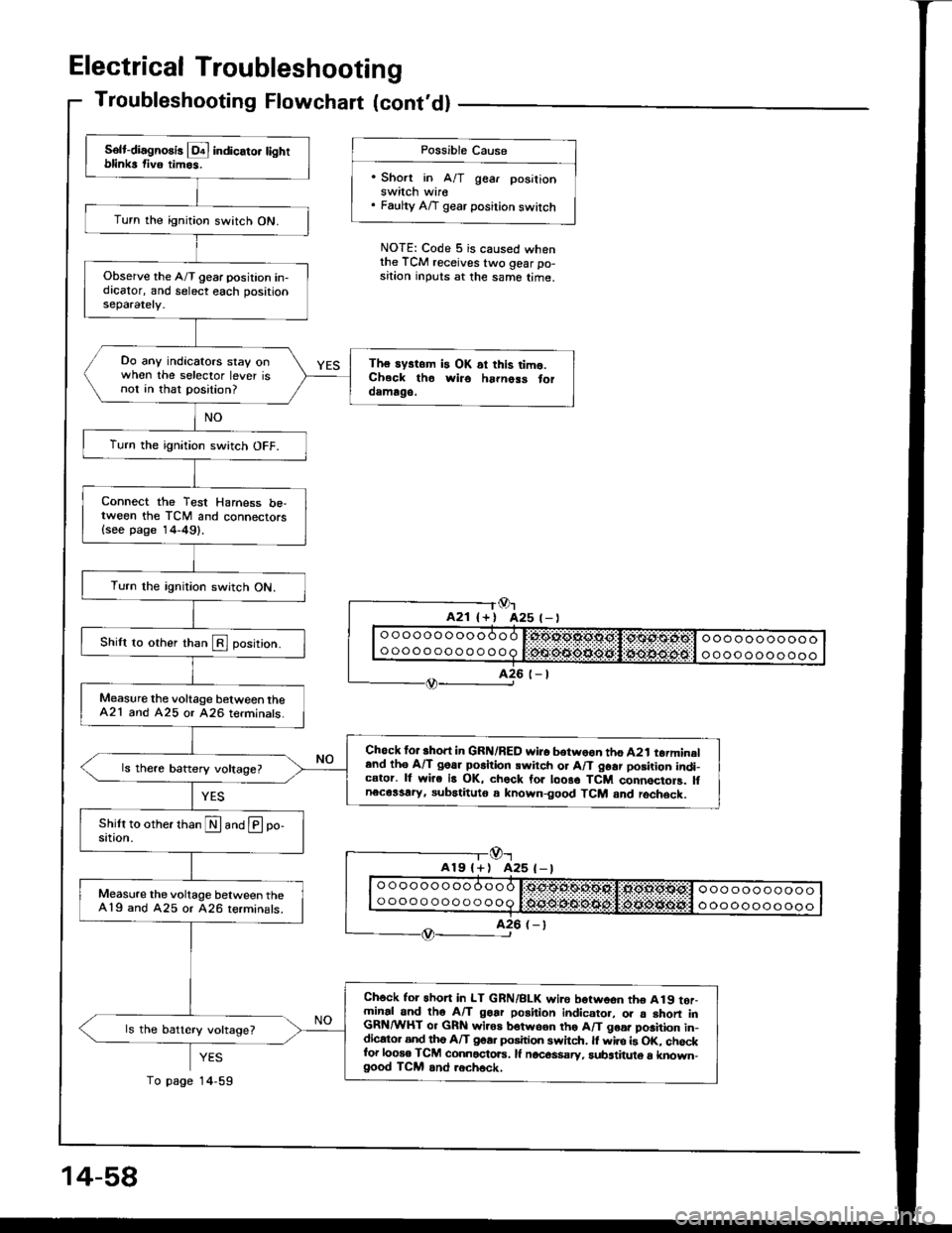
Electrical Troubleshooting
Troubleshooting Flowchart lcont'dl
Possible Cause
'Short in A/T gear posilionswitch wire. Faulty A/T gear position switch
NOTE: Code 5 is caused whenthe TCM receives two gear po-sition inputs at the same time.
Or425 t- |
-l@r
A19l+) A25 (-)
YES
14,59
Solt-diagno8is l!4 indicato. tightblinks fiv6 timos.
Turn the ignition switch ON.
Observe the A/T gear position in-dicator, and select each positionseparately.
Do any indicators stay onwhen the selector lever isnot in that position?
The systom is OK ai this timo.Ch.ck tho wiro ha|noss toroamago.
Turn the ignition switch OFF.
Connect the Test Harness be,tween the TCM and connectors{see page 14-49}.
Turn the rgnition switch ON.
Shilt to other than E position.
Measure the voltage b€tween theA21 and A25 or 426 terminats.
Chock for short in GRN/RED wi.o botwoon tho A2t torminaland th6 A/T goar po6ition swirch or A/T 96ar posirion indi-cator. lf wire is OK, chock for loo8o TCM connocioF. lfnecassary, subatituto a known-good TCM and rochsck.
Measure the voltage between the419 and A25 or 426 terminals.
Ch6ck for 6hon in LT GRN/BLK wi.e borwoon tho A19 tor-minal and tho A/T goar position indicato., o. a shon inGRN/WHT or GRN wiros botwson tho A/T goa. position in-dicato. and tho A/T goa. position swhch. ll wire is OK. chockfor looso TCM connactoE. lf nocos$sry, substituto a known-good TCM and .ech6ck,
ls the battery voltage?
14-58
To page
Page 451 of 1413
14-58
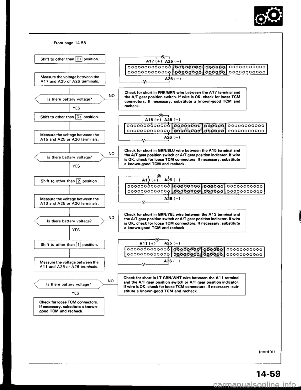
Measure the voltage between theAl l and 425 ot 426 tetminals.
ls thgre battery voltage?
YES
shift ro other than E posirion.
Measure the voltage belween lheA17 and A25 or A26 terminals.
Chock to. short in PNK/GRN wire betwoon tho Al7 torminal andth6 A/T gsar position switch. It wire is OK, chsck for looso TCMconnoctors. lf nocessary, substitute a known-good TCM androch€ck.
ls there battery voltage?
Shifi to other than E] position.
Measure the voltage between theA15 and A25 or 426 terminals.
Chock for short in GRN/BLU wire betweon the A15 terminal andthe A/T gosr position switch or A/T g€a. position indicato.. ll wirois OK, chock for loose TCM connectors. ll nocessary, substitulsa known-good TCM and rochock.
ls there battery voltage?
Shilt to other than E position.
Measure the voltage between theA13 and A25 or 426 terminals.
Chock for short in GRN/YEL wire betweon ths A13 torminal andthe A/T gear position switch or A/T gear posilion indicator. l{ wirois OK, check lor loose TCM connectors. lI necessarv, substitutaa known-good TCM and rechsck.
ls there battery voltage?
Shift to other rhan I oosirion.
Chock tor shon in LT GRN/WHT wi.e b€twoan th6 A1'l lerminaland the A/T gear position switch or A/T gear position indicator.lf wira b OK, ch6ck foi loose TCM conneclors. lf noc€ssary, sub-stituto a known-good TCM and rocheck.
Chock for looso TCM conn€ctors.lf noce$ary, substitute a known-good TCM and recheck.
oooooooooooo
oooooooooooo
ooooooooooo
oooooooo ooo
ooooooooooo
ooooooooooo
oooooooooooo
oooooooooooo
oooooooooooo
oooooooooooo
ooooooooooo
ooooooooooo
ll
{cont'd)
14-59
Page 452 of 1413
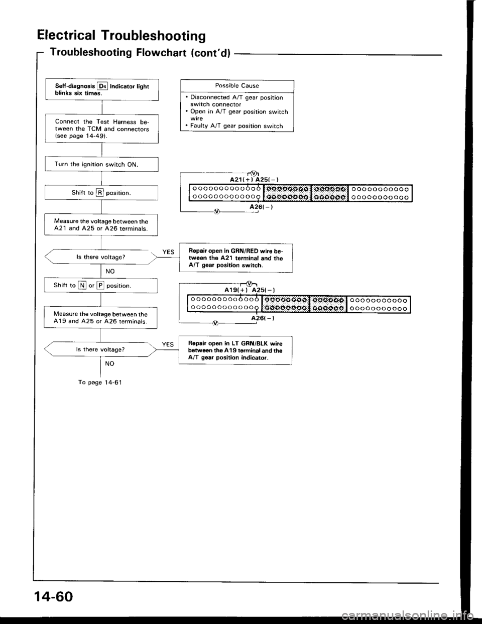
Electrical Troubleshooting
Troubleshooting Flowchart {cont'dl
ls there voltage?
ls there voltage?
NO
To page l4-61
- - r9ta21(+ I A25{-)
Self-diagnosis E indicator lightblinka six timos.
Connect the Test Harness be,tween the TCM and connectors(see page '14-49).
Turn the ignition switch ON.
Measure the voltage between theA21 and 425 or 426 terminals.
Ropair open in GRN/RED wire be,tweon th6 A21 terminal and theA/T gssr position switch.
Shilt ro N or E position.
Measure the voltage between theA19 and A25 or A26 terminals.
Ropair open in LT GRN/BLK wireb€tw6on the 419 torminal and th€A/T gear position indicato..
Possible Cause
. Disconnected A/T gear positionswrtcn connector' Open in A/T gear position switch
. Faulty A/T gear position switch
oooooooooooo
ooooooooooooooooooooooo
ooooooooooo
A25t-l
oooooooooooo
ooooooooooooooooooooooo
ooooooooooo
14-60
Page 453 of 1413
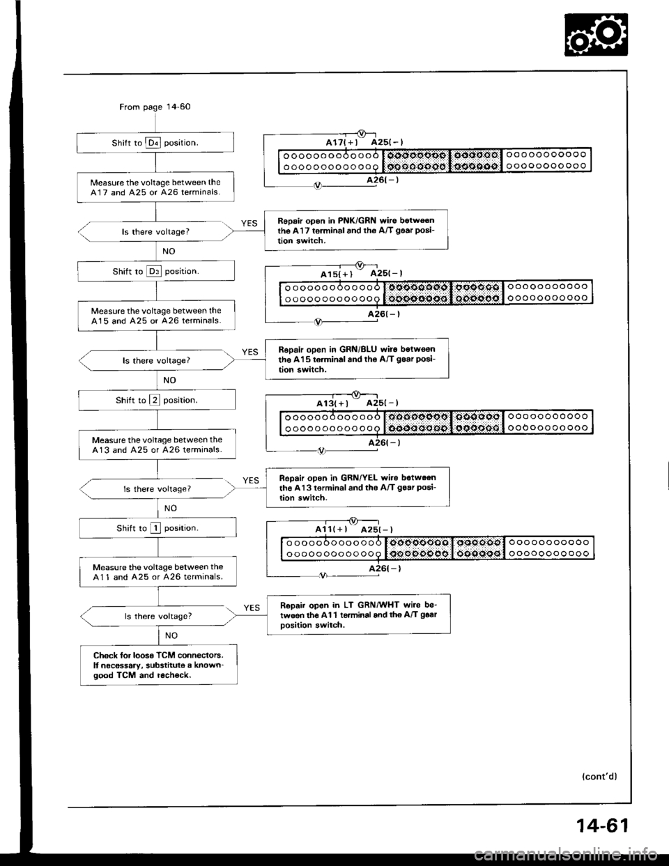
Measure the voltage between theA17 and 425 or A26 terminals.
Roprir opon in PNK/GRN wire botwoonthe A17 torminal and rh6 A/T goar posi-
tion switch.
Measure thevoltage between theA15 and A25 or A26 terminals.
Ropair open in GRN/BLU wir6 bolwoenthe A15 r6.minal and tho A/T goar posi-
tion switch.
Measure the voltage between theA13 and A25 or A26 terminals.
ReDair open in GRN/YEL wito botw€onthe Al3 torminaland th€ A/T goar posi-
lion switch.
Measure the voltage between theA11 and A25 or A26 terminals.
Ropaii opon in LT GRN/WIIT wiro bo-tw€en the A 1 1 te.minal and tho A/T goar
oosition switch.
Check lor loos€ TCM connectors.It necossaty, substituto a known_good TCM and r6ch6ck.
ooooooooooo
ooooooooooooooooooooooo
oooooooooooo
ooooooooooo
ooooooooooooooooooooooo
oooooooooooo
ooooooooooo
ooOoooooooooooooooooooo
oooooooooooo
ooooooooooo
ooooooooooooooooooooooo
oooooooooooo
voltage?
voltage?
All(+ I
voltageT
(cont'dl
14-61
Page 454 of 1413
Electrical Troubleshooting
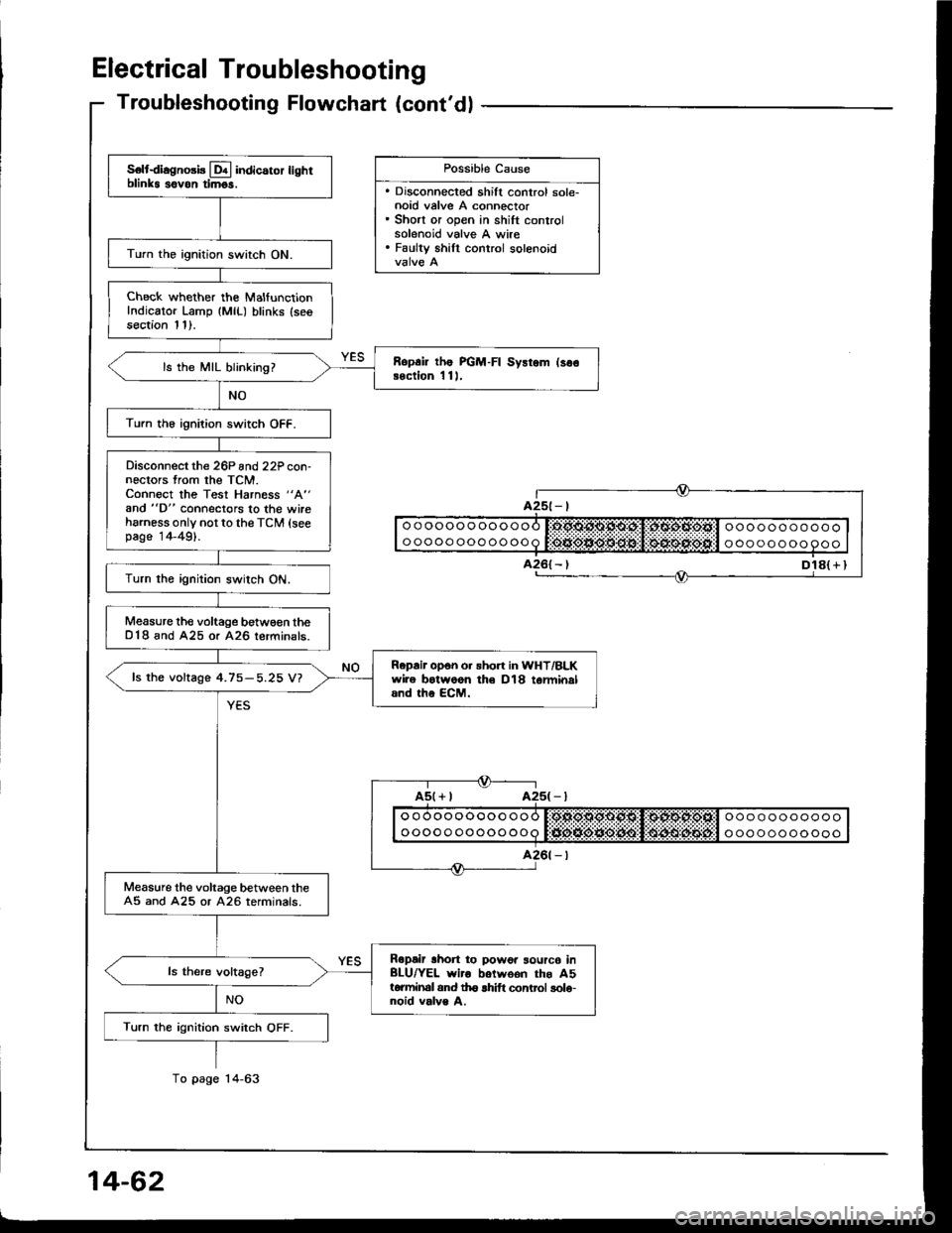
S€ltdiagno3b Lql indicaror lighrblinks sovon timgs.
Turn the ignition switch ON.
Check whether the MalfunctionIndicator Lamp {MlL) blinks (seesection 11).
Ropai lhe PGM-FI Sysrem (so€Bection 1 11,ls the MIL blinking?
Turn th6 ignition switch OFF.
Disconnect the 26P and22P con-nectors from the TCM.Connect the Test Harness "A"
and "D" connectors to the wireharness only not to the TCM (seepage 14-49).
Turn the ignition switch ON.
Measure the voltage betw€€n theD18 and A25 or A26 lerminals.
Repair opon o. sho.t in WHT/BLKwire botwoon th€ D18 tarminaland the ECM.
fs the voftage 4.75-5.25 V?
Measure the voltage between theA5 and A25 or A26 terminals.
Ropair lhon to powor sourc6 inBLU/YEL wiro botwoon the A5torminal and th6 lhift control solo-noid valve A.
Turn the ignition switch OFF.
Troubleshooting Flowchart (cont'dl
Dl8( r I
Possible Cause
. Discohnected shift control sole-noid valve A connector. Short or open in shift controlsolenoid valve A wire. Faulty shill control solenoid
ooooooooooooooooooooooo
ooooo oooooooa t:tJio*ie*O:lt$!l $4lrulitEijt'l o oo oooooooo