control arm HONDA INTEGRA 1994 4.G Workshop Manual
[x] Cancel search | Manufacturer: HONDA, Model Year: 1994, Model line: INTEGRA, Model: HONDA INTEGRA 1994 4.GPages: 1413, PDF Size: 37.94 MB
Page 54 of 1413
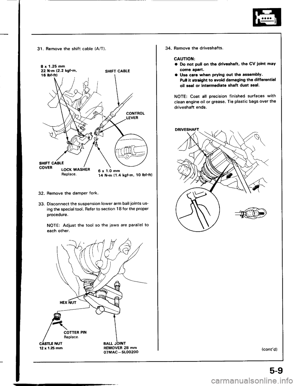
31. Remove the shift cable
I x 1.25 mm22 f.m 12.2 kgl'rn'16 tbl.ftl
(A/T).
SHIFT CABLE
32.
33.
CONTROLLEVER
SHIFT CAALEcovER locx usiea6 x 1.0 mm14 N.m t1.4 kgf.m, 10 lbl'ftlReplace.
Remove the damper tork.
Disconnect the suspension lower arm balljoints us-
ing the special tool. Refer to section 1 8 tor the proper
procedure.
NOTE: Adjust the tool so the iaws are parallel to
each other.
REMOVER 28 mmoTMAC-S10020012 x 1.25 mm
5-9
34. Remove the driveshatls.
CAUTION:
a Do not pull on tho ddv$halt, tho CV ioint mav
como apan.
a Uso caro whsn prying out tho assombly.
Pult it slraight to avoid damaging th6 differantial
oil soal or intormodiato shaft dust seal.
NOTE: Coat all precision tinished surfaces with
clean engine oil or grease. Tie plastic bags over the
driveshaft ends.
(cont'd)
Page 99 of 1413
wEc
6-38
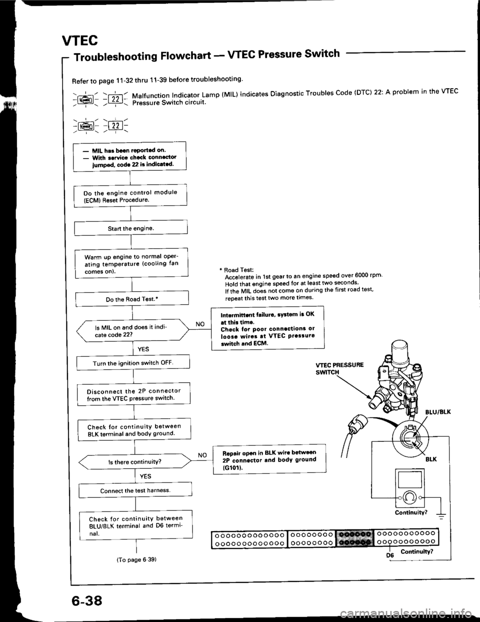
Troubleshooting Flowchart - VTEC Pressure Switch
Refer to page 11-32thru 11-39 beJore troubleshooting'
-.+- -r";-r- Malfunction Indicator Lamp (MlL) indicates Oiagnostic Troubles Code (DTC) 22: A problem in the VTEC- l{{?l- ;l ziz r: pressur€ Switch circuit.
-lr@l- |22 1-
* Road Test:Accolerato in lst gear to an engine speed over 6000 rpm
Hold that engine speed for at least two seconos'
lf the MIL does not come on during the first road test'
reoeat this test two more limes.
- MIL har bagn.oportcd on.- With t.rvic. chack connactor
iump.d, cod€ 22 it indic.t.d.
Do the engine control module(ECM)Reset Procedure.
Warm !p engine to normal oper-
ating temperstur€ (cooling fan
comes on).
Do the Boad T€st.'
Intc.mift.nt failu.o, ry3tom ia OK
at thi. tim..Chack for pool connaction3 ol
loo!. rvirat at VTEC Ptasturo3whch and ECM.
ls MIL on and does it indi'
cate code 22?
Turn lhe ignition switch OFF
Disconnect the 2P connector
lrom the VTEC Pressure switch.
Check Ior continuity between
BLK terminal and body ground.
Rcpair opcn in BLK wit. botwcon
2P connector rnd body ground
tG101l.
Check for continuity between
8LU/8LK terminal and D6 termi'
nal.
(To page 6 39)
Page 115 of 1413
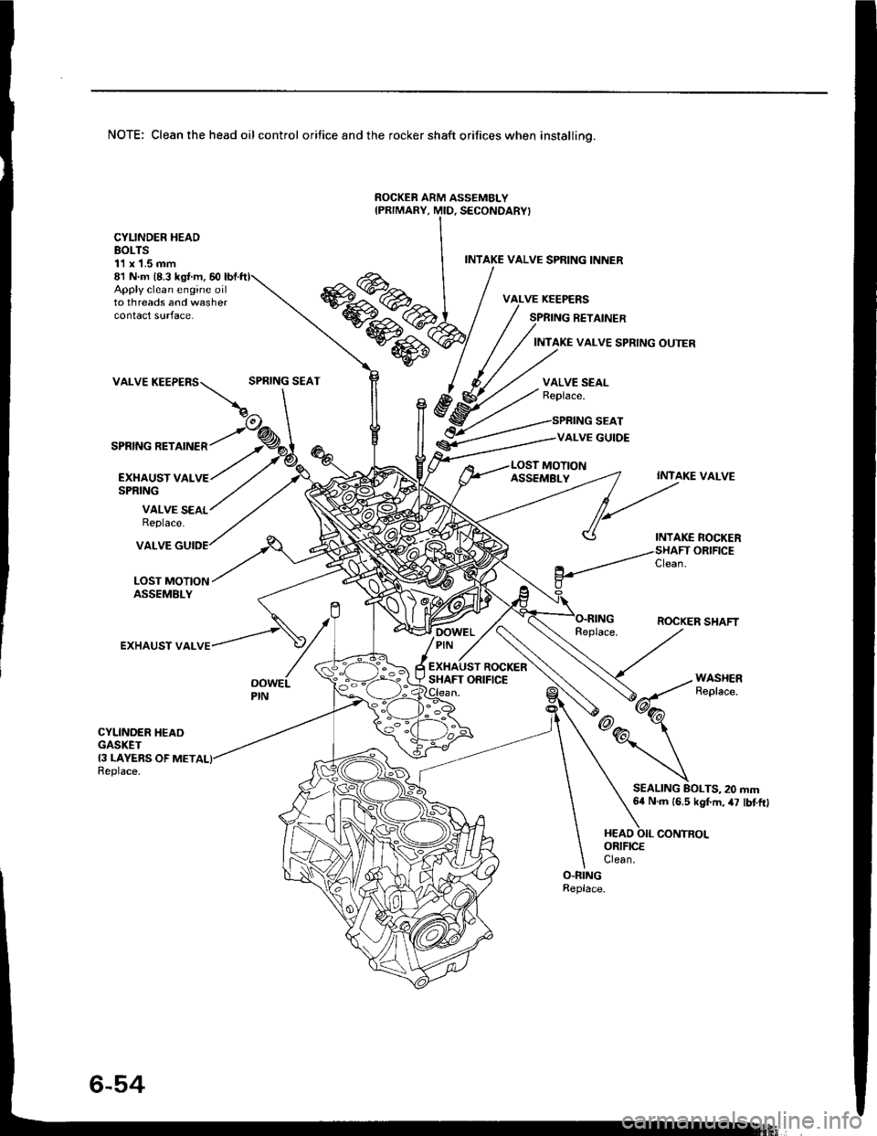
NOTE: Clean the head oil control orifice and the rocker shaft orifices when installino.
ROCKEB ARM ASSEMBLY
Apply clean engine oilto threads and washercontact surface.
81 N m (8.3 ks{ m, 60
VALVE
SPRING RETAINER
CYLINDER HEADBOLTS11 x 1.5 mm
EXI{AUST VALSPRING
INTAKE VALVE SPRING INNER
SPRING RETAINER
INTAKE VALVE SPRING OUTER
SPRING SEATVALVE SEALReplace.
SPRING SEAT
VALVE GUIDE
MOTION
VALVE SEALReplace.
ASSEMBLYINTAKE VALVE
INTAKE ROCKERORIFICE
LOST MOTIONASSEMBLY
VALVE
EXHAUST VAL
Clean.
ROCKER SHAFTDOWELPIN -,
ROCKERSHAFT ORIFICEOOWELPIN
CYLINDER HEAOGASKET13 LAYEBS OF METReplace.
SEALING BOLTS, 20 mm64 N.m 16.5 kgf.m, 47 lbtftl
Page 189 of 1413
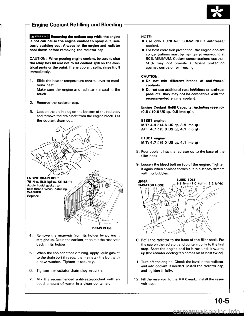
@ ne-oving the radiator cap while the engine
is hot can cause the engine coolant to splay out, seri-
ously scalding you. Always let the engine and radiatol
cool down betore removing the radiator cap.
CAUTION: When poudng engine coolant, be sure to shut
the relay box lid and not to let coolant spill on the elec-
tlical pans or the paint. ll any coolant spills, rinse it otf
immediately.
1. Slide the heater temperature control lever to maxi-
mum heat.
Make sure the engine and radiator are cool to the
touch.
2. Remove the radiator cao.
3. Loosen the drain plug on the bottom of the radiator,
and remove the drain bolt from the enoine block. Let
the coolant drain out.
ENGINE DRAIN BOLT78 N.m {8,O kgt.m, 58 lbt.ftlApply liquid gasker tobolt thread when installing.WASHERReplace.
5.
Remove the reservoir from its holder by pulling it
straight up. Drain the coolant, then put the reservoir
back in its holder.
When the coolant stops draining, apply liquid gasket
to the drain bolt threads, then reinstallthe bolt with
a new washer. Tighten it securely
6. Tighten the radiator drain plug securely.
7. Mix the recommended antifreeze/coolant with an
equal amount of water in a clean container.
NOTE:
. Use only HONDA-RECOMMENOED antifreeze/
coolant.
a For best corrosion protection, the engine coolant
concentrations must be maintained year-round at
50% MINIMUM. Coolant concentrations less than
50% may not provide sufficient protection
against corrosion or freezing.
CAUTION:
a Do not mix ditterent blands ot anti-freeze/
coolants.
a Do not use additional rust inhibitois or anti-rust
products; they may not bs compatibl€ with the
recommgndsd engins coolant.
Engin€ Coolant Retill Capacity: including reservoir
{0.6 t (0.6 US qt, 0.5 lmp qt)).
81881 engine:
MlTt 4.4 | (4.6 US qt, 3.9 lmp qr)
Afft 4.7 [ (5.O US qt,4.1 lmp qt]
Bl8Cl engine:
Mnt 4.7 | (5.0 US qt.4.1 lmp qt)
8. Pour coolant into the radiator up to the base of the
filler neck.
9. Loosen the bleed bolt on top of the engine. Tighten
it again when coolant comes out in a steady stream
with no bubbles.
BLEED BOLT
1O. Refill the radiator to the base of the tiller neck. Put
the cap on the radiator. and tighten it only to the tirst
stop, Stan the engine and let it run until it warms
up (the radiator cooling fan comes on at leasttwice).
11. Turn oft the engine. Check the level in the radiator,
and add coolant it needed. Install the radiator caD,
and tighten it fully.
'1 2. Fill thereservoirto the MAX mark. lnstallthe reser-
voir cap.
9.8 N.m (1.O kgl.m, 7.2 lbf.ftl
Engine Coolant Refilling and Bleeding
10-5
Page 231 of 1413
How to Read Flowcharts
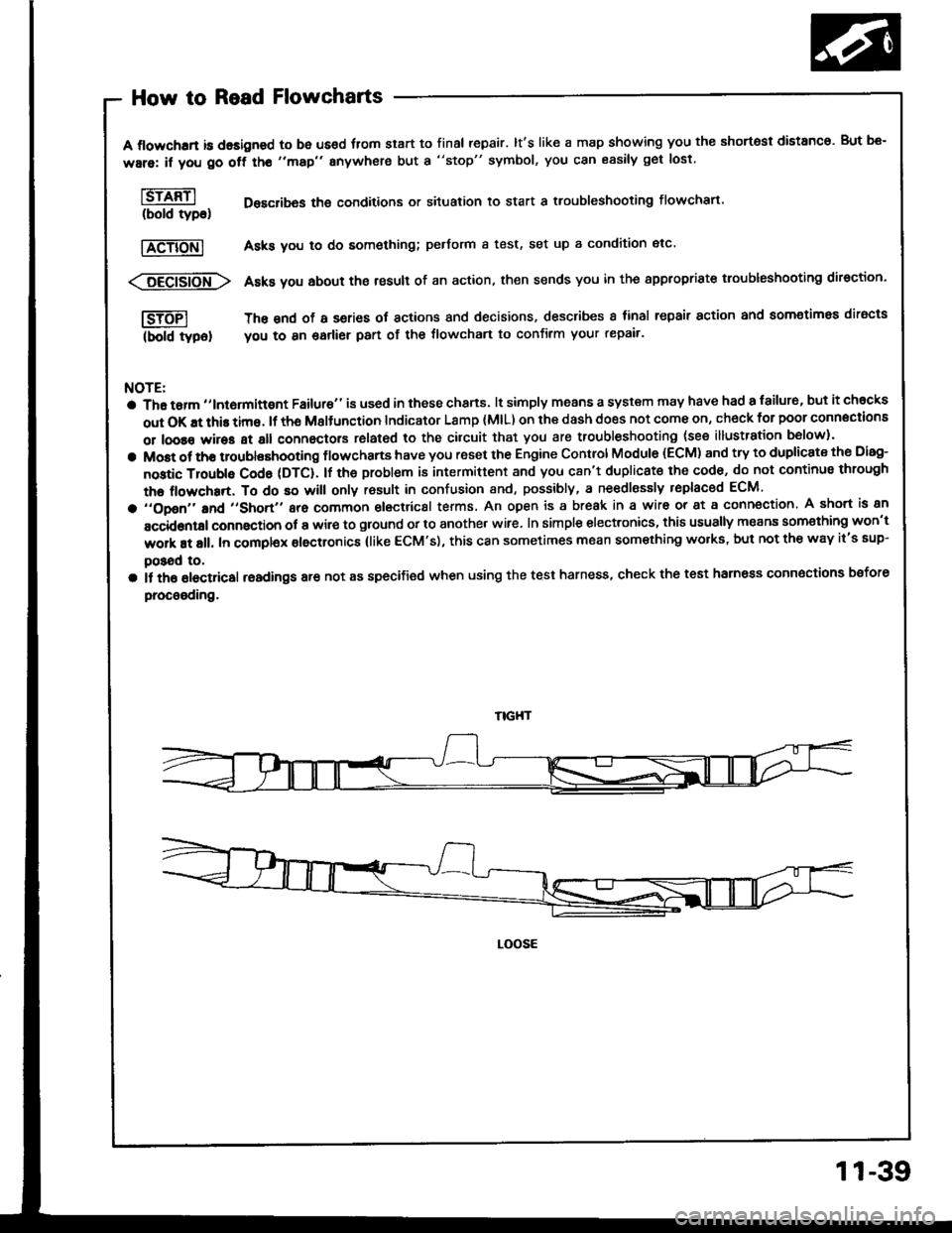
A flowchrrt is dasigned to be us€d fiom start to final repair. lt's like a map showing you the shortest distanco. But be-
ware: if you go off tho "map" anywhere but a "stop" symbol, you can easily get lost
l6rffil Desclibas the conditions or situation to start a troubleshooting flowchart.(bold tyDo)
|TeTiONl Asks you to do something; pedorm a test, set up a condition etc'
<:6Eei6io-fr\> Asks you about the result of an action, then sends you in the appropriste troubleshooting direction.
I-SJTFI The snd of a series ot actions and decisions, describes I tinal repair action and aomotimea diracts
(bold typel you to 8n garlier part of the tlowchart to confirm your repair'
NOTE:
a Tha tarm ,,lntormittgnt Failure" is used in these chans. lt simply means a system may have had a failur6, but it chocks
out OK !t this time. lf th6 Msltunction Indicator Lamp (MlL) on ihe dash does not come on, check for poor connections
or loose wires at all connectors rolated to the cilcuit that you are troubleshooting (see illustration b6low).
a Most ot tho troublashooting flowchans have you reset the Engine Control Module (ECM) and try to duplicate the Disg-
nostic Troubls Cod6 (DTC). lf the problem is intermittent and you c8n't duplicat€ the cod6, do not continus through
the flowchart, To do so will only rosult in confusion and, possibly, a ne€dlessly replaced ECM
a ,,opon,'and ,,short,, are common electrical terms. An open is a break in a wir6 or at a conn€ction. A short is an
accidontal connaction ot a wir€ to ground or to another wire. In simple electronics, this usually means som€thing won't
work at all. In complex electronics (like ECM's), this can sometimes mean something wolks, but not the way it's sup-
poSad to,
a il th6 olectricsl readings are not as specified when using the test harness, check the test harness connoctions bsfore
procooding.
LOOSE
11-39
Page 271 of 1413
ldle Control System
ldle Air Control (lACl Valve
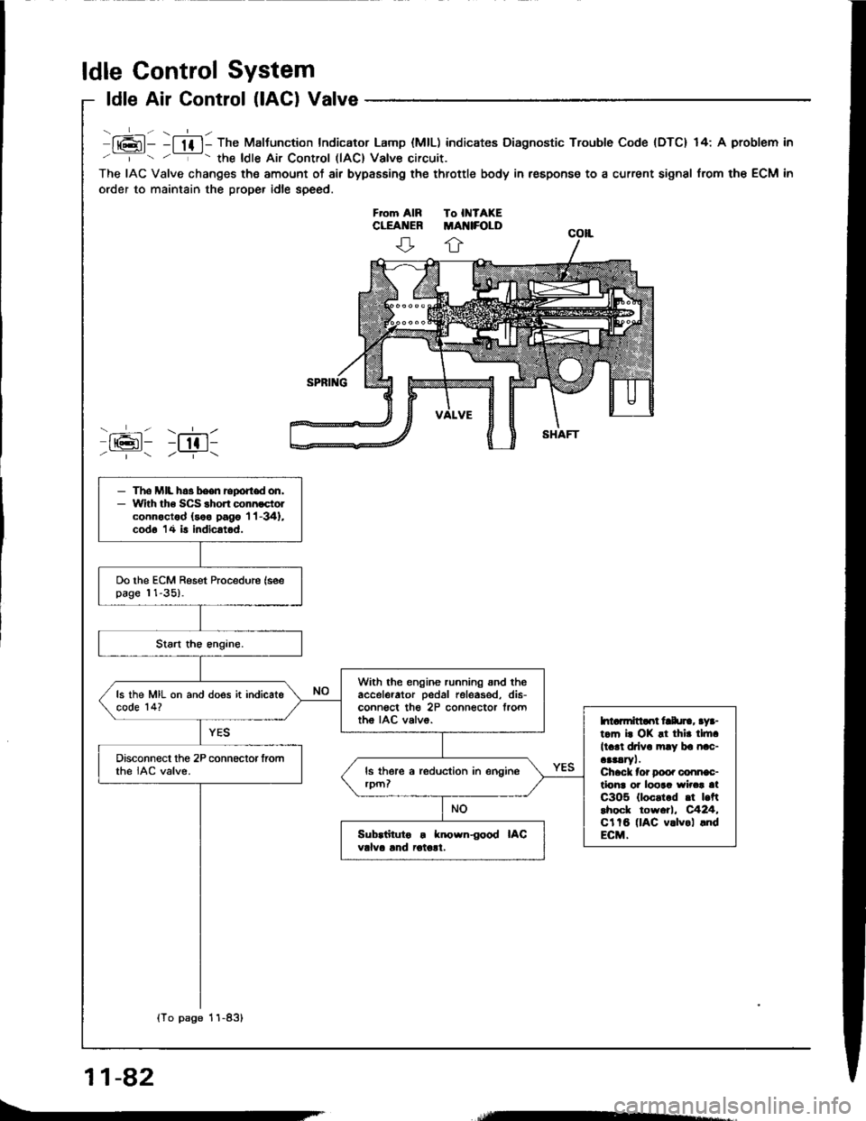
lt6l- -l lf l- The Maltunction Indicator Lamp (MlL) indicates Diagnostic Trouble Code {DTC} 14: A problem in
' '- the ldle Air Control llAC) Valve circuit.
The IAC Valve changes the amount of air bypasEing the throttle body in respons€ to a current signal from the ECM in
order to maintain the proper idle speed.
ffi: r;611/ | /--T-\
- The MIL h.3 been report don,- With tho SCS shon connoctolconnoctod (soo pago 'l 'l -341,
cod6 14 is indicatod.
Do the ECM Reset Procedure (seepage 11-35).
With the engine running snd theaccelerator pedal releas€d, dis-conn€ct th€ 2P connector frorttho IAC valvo.
ls the MIL on and does it indicatecode 14?
htarmitlaot frlu]., aya-t.m i. OK !t thir tlft.
ll.rl drlv. mly ba nac-aaaaryl.Chack tor Doo. conn€c-tlonr oi loora wirca atC3O5 (loc.t.d .t |.ftlhock tow.tl, C424,Cl tB (lAC v.lvol .ndECM.
Disconnect the 2P connector fromthe IAC valve.
Sub.iituto . known{ood IACvdva lnd iotolt.
{To page 11-83}
11-82
Page 283 of 1413
ldle Control System
Fast ldle Thermo Valve
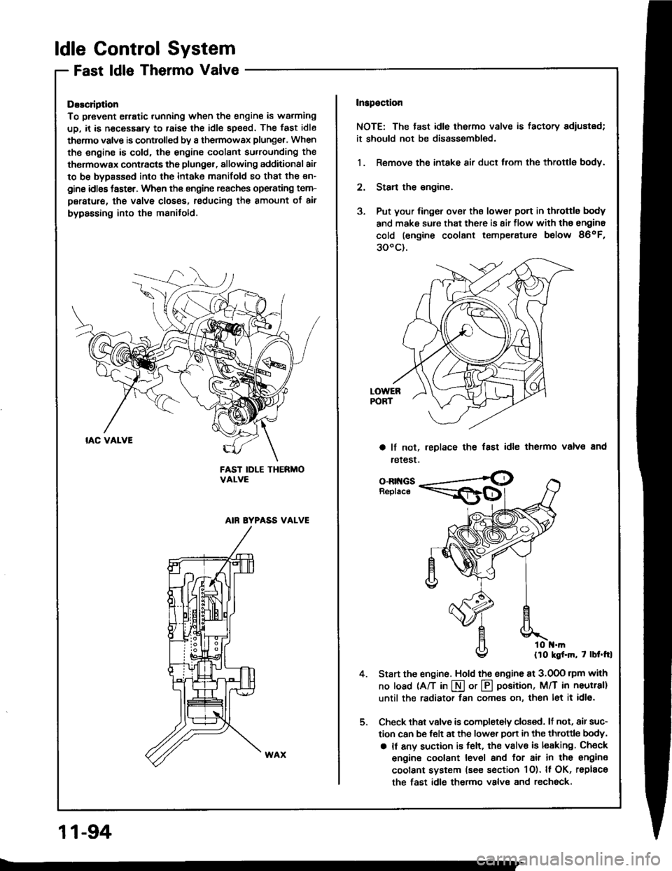
DEscliptlon
To prevent erratic running when the engine is warming
up, it is n€cessary to raise the idle speed. The fast idle
thermo valve is controlled by a thermowax plunger, When
the engine is cold. the engine coolant su.rounding the
thermowax contracts the plunger, allowing additional air
to be bypassed into the intake manifold so that the en-
gine idlss taster. When the engine reaches operating tem-
peratur€, the valve closss, reducing the amount of air
bypassing into the manifold.
FAST IDLE THERMOVALVE
AIN EYPASS VALVE
Inspaction
NOTE: The tast idle thermo valve is factory adiustsd;
it should not be disassombl€d.
1. Remove the intake air duct from the throttlg body.
2. Stan the engine.
3. Put your finger over ths lower port in throttle body
and make sure that there is 8ir flow with tho engine
cold (engine coolant temperatute below 86oF,
300c).
a lf not,
retest.
leplace the fast idle thermo valvs and
4.
o-Rr{GsReplace
llo kgf.m, 7 lbt.trl
Start the engine. Hold the sngine at 3.0OO rpm with
no load (A/T in I or @ position, M/T in neutral]
until the radiator fan comes on, then let it idl6.
Check thst valve is completely closed. lt not, air suc-
tion can be telt at the lower Don in the throttle body,
a It any suction is felt, the valve is leaking Check
engine coolant level and for air in tho engine
coolant system (see section 1O). ll OK, rsplace
the fast idle thermo valve and rechock.
11-94
Page 304 of 1413
Intake Air System
System Troubleshooting Guide
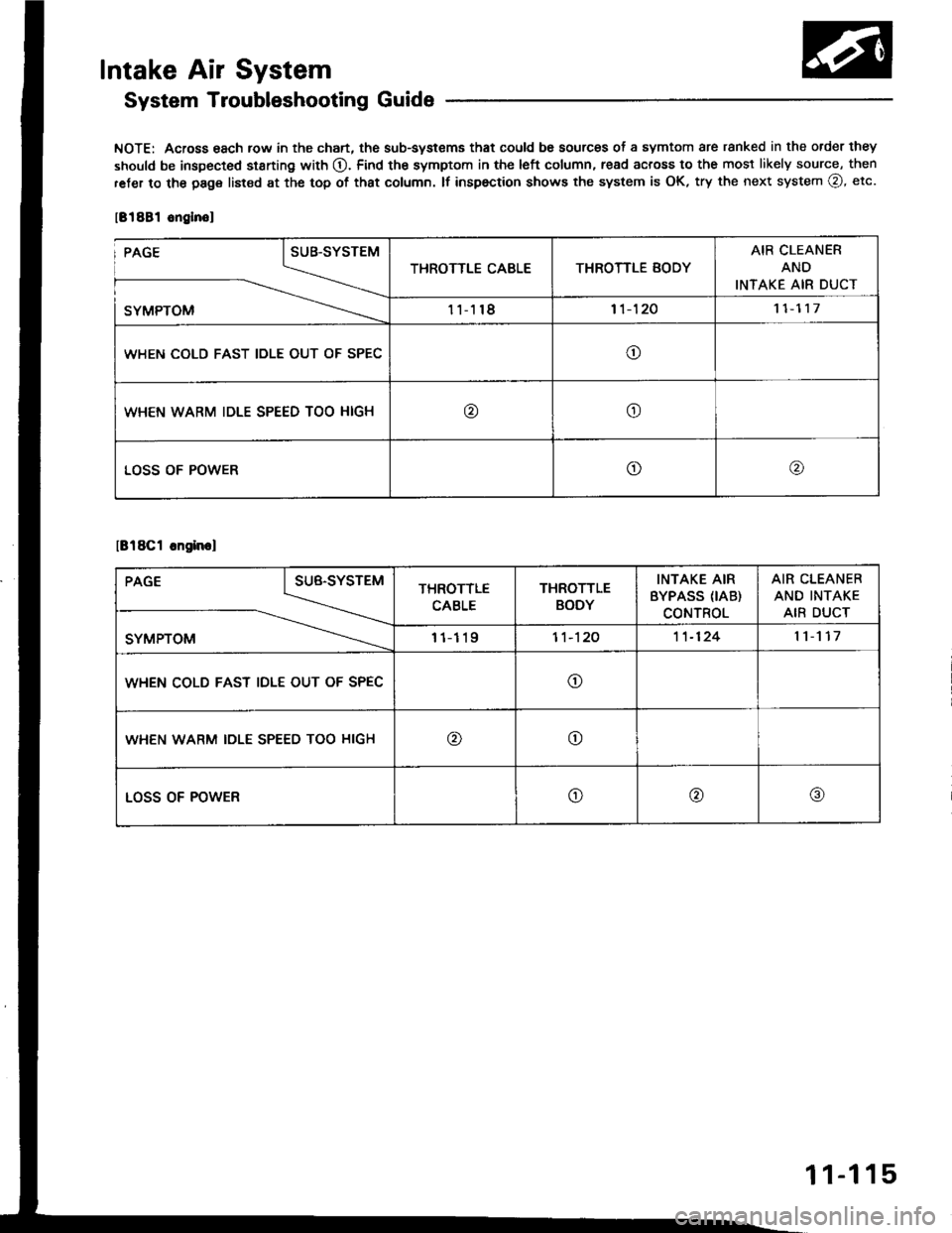
NOTE: Across 6ach row in the chart, the sub-systems that could be sources of a symtom are ranked in the order they
should be inspected st8rting with O. Find the symptom in the left column, read across to the most likely source, then
ret€r to the page listod at the top of that column. tf inspection shows the system is OK, try the next system @, etc.
181881 onglnol
't 1-11711-118
WHEN COLD FAST IOLE OUT OF SPEC
WHEN WARM IDLE SPEED TOO HIGH
lB18Cl cngin.l
PAGE I sue-svsreu
_\.-..\
sYMPToM \---...-
THROTTLE
CABLE
THROTTLE
BODY
INTAKE AIR
BYPASS (IAB)
CONTROL
AIR CLEANER
AND INTAKE
AIR DUCT
111191'�t -12011-1241l117
WHEN COLD FAST IDLE OUT OF SPECo
WHEN WARM IDLE SPEED TOO HIGHoo
LOSS OF POWERo@@
11-115
Page 319 of 1413
Emission Control System
SystemDescription
The emission control system includes a Three Way Cata-
lytic Convener (TWC), Positive Crankcase Ventilation(PCV) system and Evaporstive Emission {EVAP) Contfol
syst€m. The emission control system is designed to meet
federsl and stats emission standards.
Tailpipe Emission
Inspection
f!fifil oo nor amoro ou]rng rnr! Foacqurr. ^!op
any open flame away from yout wotk atca.
Start the engine. Hold the engine at 3,OOO rpm with
no load (A/T in @ or@ position, M/T in neutral) until
the radiator fan comes on, then let it idle,
Connect a tachometer.
Check and adiust the idle speed, if necessary (sss
page 1 1-95).
Warm up and calibrate the CO meter according to
the meter manutacturer's inst.uctions.
Check idle CO with the headlights, hester blower,
rear window defogger, cooling fan, and air condition-
er otf.
NOTE: (Canada) Pull the parking br8ke lever up.
Stan the engine, then check that the headlights are
off.
CO meter should indicate 0.1 maximum.
11-130
Page 417 of 1413
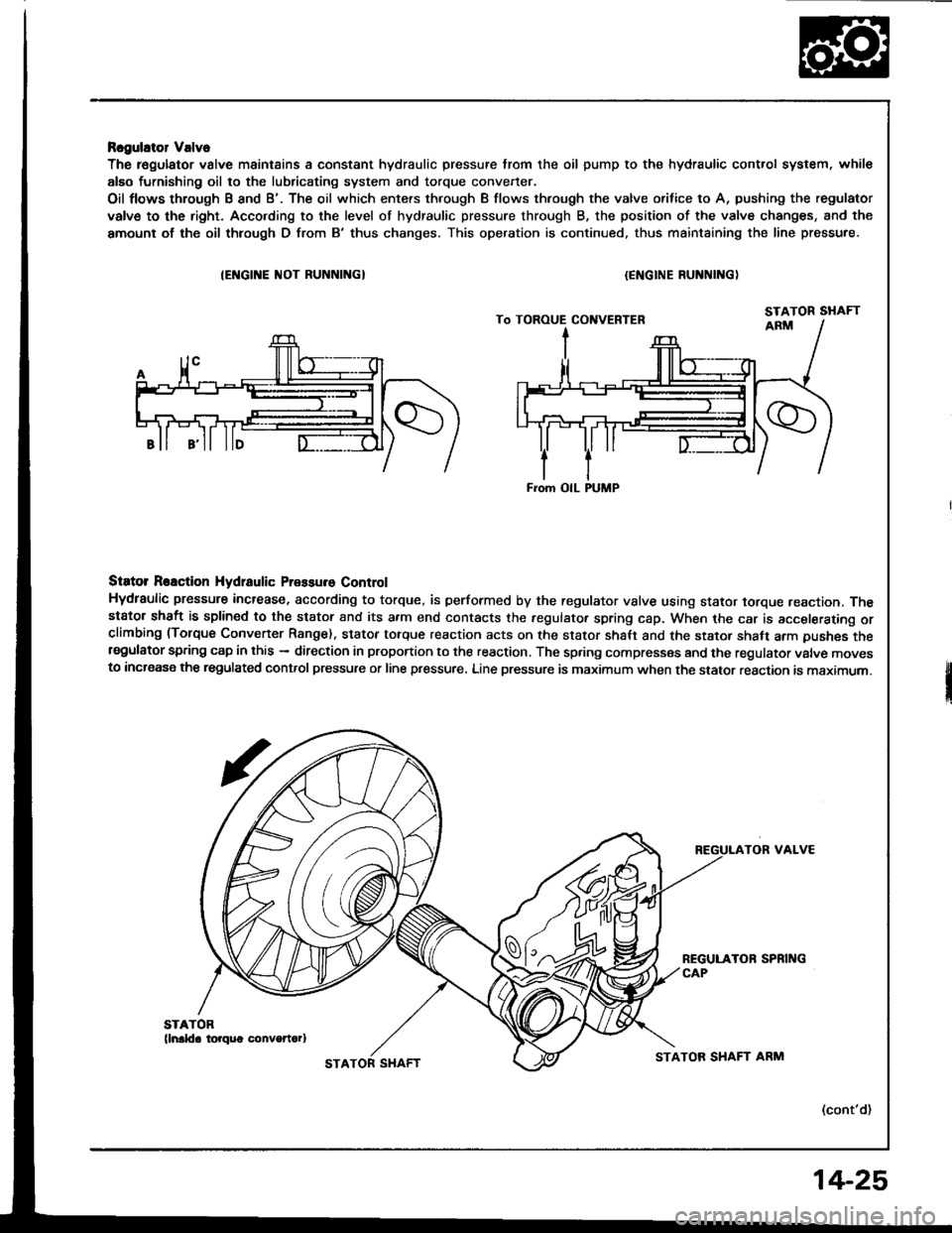
Rcgulator Valve
The r€gulator valve maintains a constant hydraulic pressure from the oil pump to the hydraulic control system, whil€
alEo furnishing oil to the lubricating system and torque convener.
Oil flows through B and B'. The oil which enters through B flows thfough the valve orifice to A, pushing the regulator
valve to the right. Acco.ding to the level of hydraulic pressure through B, the position of the valve changes, and the
amount of the oil thlough D from B'thus changes. This operation is continued. thus maintaining the line pressure.
IEI{GINE ]IIOT RUNNINGI{ENGINE RUNNING)
Siator Reaction Hydtaulic Pressure Control
Hydraulic pressure increase, according to torque, is performed by the regulator vslve using stator torque reaction. Thestator shaft is splined to the stator and its a.m end contacts the fegulator spring cap. When the car is accelerating orclimbing (Torque Convener Range). stator torque reaction acts on the stator shalt and the stator shaft arm pushes thersgulator spring cap in this - direction in proportion to the reaction. The spring compresses and the regulator valve movesto increase the regulated control pressure or line pressure. Line pressure is maximum when the stator reaction is maximum.
TOR VALVE
(cont'd)
From OIL PUMP
STATOR SHAFTSTATOR SHAFT ARM
14-25