control arm HONDA INTEGRA 1994 4.G User Guide
[x] Cancel search | Manufacturer: HONDA, Model Year: 1994, Model line: INTEGRA, Model: HONDA INTEGRA 1994 4.GPages: 1413, PDF Size: 37.94 MB
Page 454 of 1413
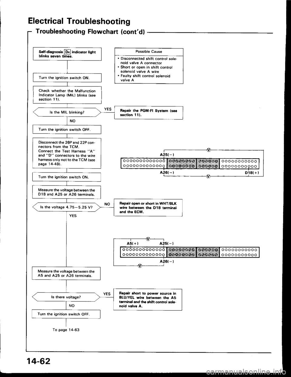
Electrical Troubleshooting
S€ltdiagno3b Lql indicaror lighrblinks sovon timgs.
Turn the ignition switch ON.
Check whether the MalfunctionIndicator Lamp {MlL) blinks (seesection 11).
Ropai lhe PGM-FI Sysrem (so€Bection 1 11,ls the MIL blinking?
Turn th6 ignition switch OFF.
Disconnect the 26P and22P con-nectors from the TCM.Connect the Test Harness "A"
and "D" connectors to the wireharness only not to the TCM (seepage 14-49).
Turn the ignition switch ON.
Measure the voltage betw€€n theD18 and A25 or A26 lerminals.
Repair opon o. sho.t in WHT/BLKwire botwoon th€ D18 tarminaland the ECM.
fs the voftage 4.75-5.25 V?
Measure the voltage between theA5 and A25 or A26 terminals.
Ropair lhon to powor sourc6 inBLU/YEL wiro botwoon the A5torminal and th6 lhift control solo-noid valve A.
Turn the ignition switch OFF.
Troubleshooting Flowchart (cont'dl
Dl8( r I
Possible Cause
. Discohnected shift control sole-noid valve A connector. Short or open in shift controlsolenoid valve A wire. Faulty shill control solenoid
ooooooooooooooooooooooo
ooooo oooooooa t:tJio*ie*O:lt$!l $4lrulitEijt'l o oo oooooooo
Page 500 of 1413
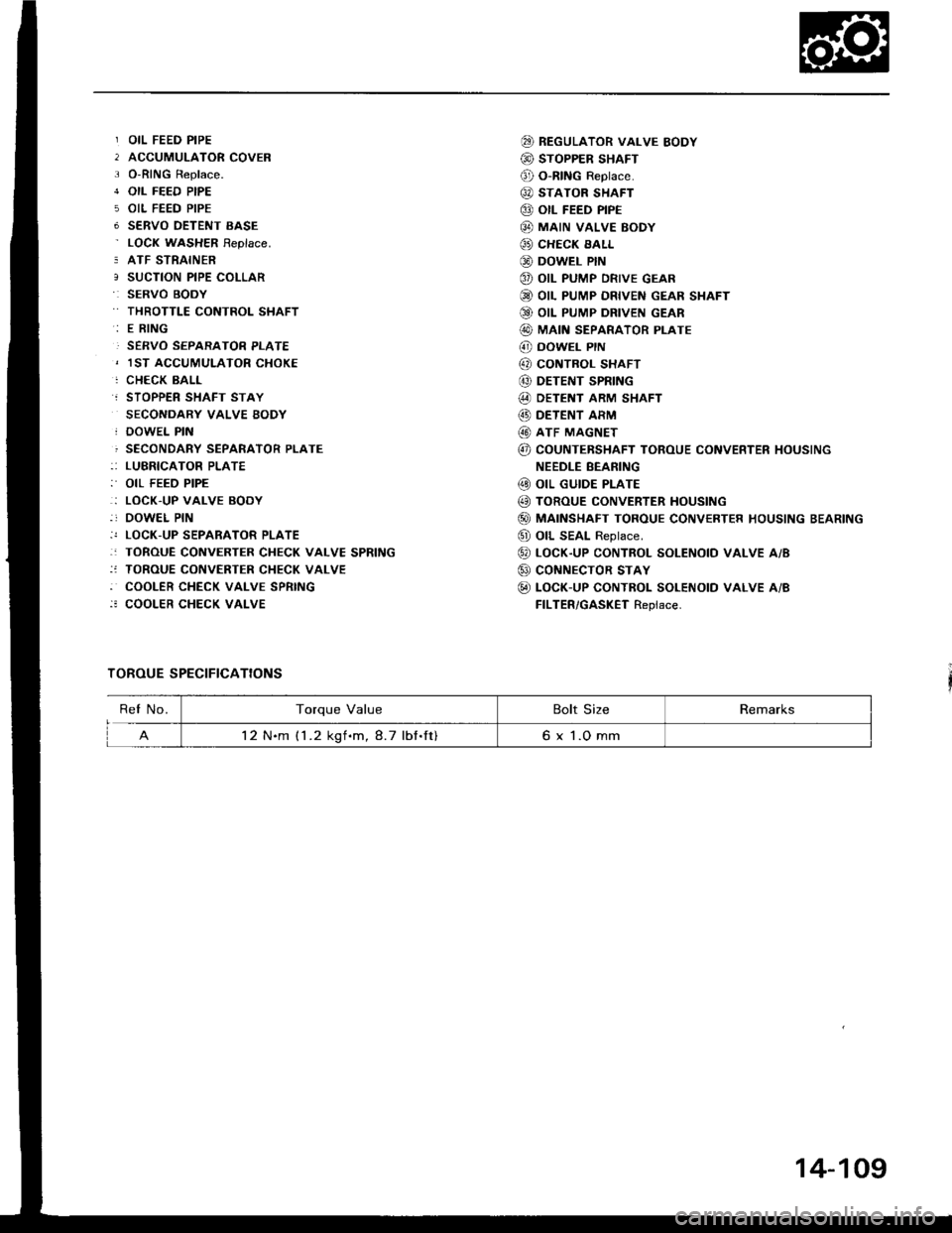
OIL FEED PIPE
ACCUMULATOR COVER
O-RING Replace.
OIL FEED PIPE
OIL FEED PIPE
SERVO OETENT EASE
LOCN WASHER Feplace.
ATF STRAINER
SUCTION PIPE COLLAR
SERVO BOOY
THROTTLE CONTROL SHAFT
E RING
SERVO SEPARATOR PLATE
1ST ACCUMULATOR CHOKE
CHECK BALL
STOPPER SHAFT STAY
SECONDARY VALVE BODY
DOWEL PIN
SECONDARY SEPARATOR PLATE
LUBRICATOR PLATE
OIL FEED PIPE
LOCK.UP VALVE BODY
DOWEL PIN
LOCK-UP SEPARATOR PLATE
TOROUE CONVERTER CHECK VALVE SPRING
TOROUE CONVERTER CHECK VALVE
COOLER CHECK VALVE SPRING
COOLER CHECK VALVE
TOROUE SPECIFICATIONS
@ REGULAToR vALvE BoDY
@ STOPPER SHAFT
@ O-RING Reptace.
@ STATOR SHAFT
@ otl FEED PIPE
@ MAIN vALvE BoDY
@ CHECK EALL
@ DowEL PIN
@ oIL PUMP DRIVE GEAR
@ OIL PUMP DRIVEN GEAR SHAFT
Q9 OIL PUMP DRIVEN GEAR
@ MAIN SEPARAToR PLATE
@ DowEL PrN
@ coNTBoL sHAFT
@ DETENT SPRING
@ DETENT ARM SHAFT
@) DETENT ARM
@ ATF MAGNET
@ COUNTEBSHAFT TOROUE CONVERTER HOUSING
NEEDLE BEANING
@ oIL GUIDE PLATE
@ TOROUE CONVERTER HoUSING
@) MAINSHAFT TOROUE CONVERTER HOUSING BEARING
@ oll SEAL Reptace.
@ LocK-up coNTRoL soLENotD vALvE A/B
@ coNNECTOR STAY
@ LOCK-UP CONTROL SOLENOTD VALVE A/B
FILTER/GASKET Replace.
ReI No.Torque ValueBolt SizeRemarks
12 N.m (1 .2 kgf.m, 8.7 lbf.ft)6 x 1.O mm
14-109
Page 506 of 1413
NOTE:
a Clean all parts thoroughly in solvent or carbuetor
cleaner and dry with compressed air.a Blow out all passages.
a When removing the valve body replace the following:. O-rings. Lock wsshers
1 . Remove the oil feed pipes from the servo body, s€r-
vo detent base, accumulatof cover, lock-uD valve
body and main valve body.
2, Remove the three bolts securing the ATF strainer and
servo detent base, then remove them.
3. Remove the three bolts securing the accumulator
cover. then remove the accumulator cover.
4. Remove the six bolts secu.ing the servo body, then
remove the servo body and separator plate.
5. Remove the bolt securing the secondary valve body,
then remove the secondary valve body and separa-
tor plate.
6. Remove the eight bolts securing the lubricator plate
and lock-up valve body, then remove the lubricatorplate, lock-up valve body and separator plate.
7. Femove the bolt securing the.egulator valve body,
then.emove the regulator valve body.
8. Remove the stator shaft and stopper shaft.
9. Remove the detent spring t,om the detent arm. thenremove the control shaft from the torque convenerhousing.
1O. Remove the detent arm and detent afm shaft t.om
the main valve bodv.
1 1 . Remove the four bolts secu.ing the main valve body,then remove the main valve body.
12. Remove the oil pump driven gear shaft, then remove
the oil pump gears.
'13. Remove the main separator plate with two dowelDtns.
14, Remove and clean the ATF magnet.
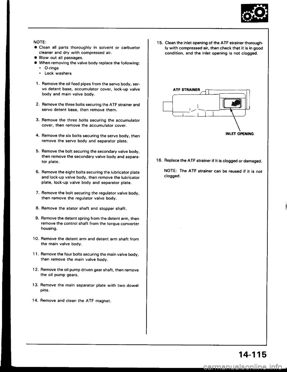
15.Clean the inlet opsning of the ATF strainer thorough-
ly with compressed air, then check that it is in good
condition, and the inlet opening is not clogged.
II{LET OPENING
Replace the ATF strainer it it is clogged or damaged.
NOTE: The ATF strainer can be reused if it is notclo9ged.
16.
14-115
Page 547 of 1413
2.
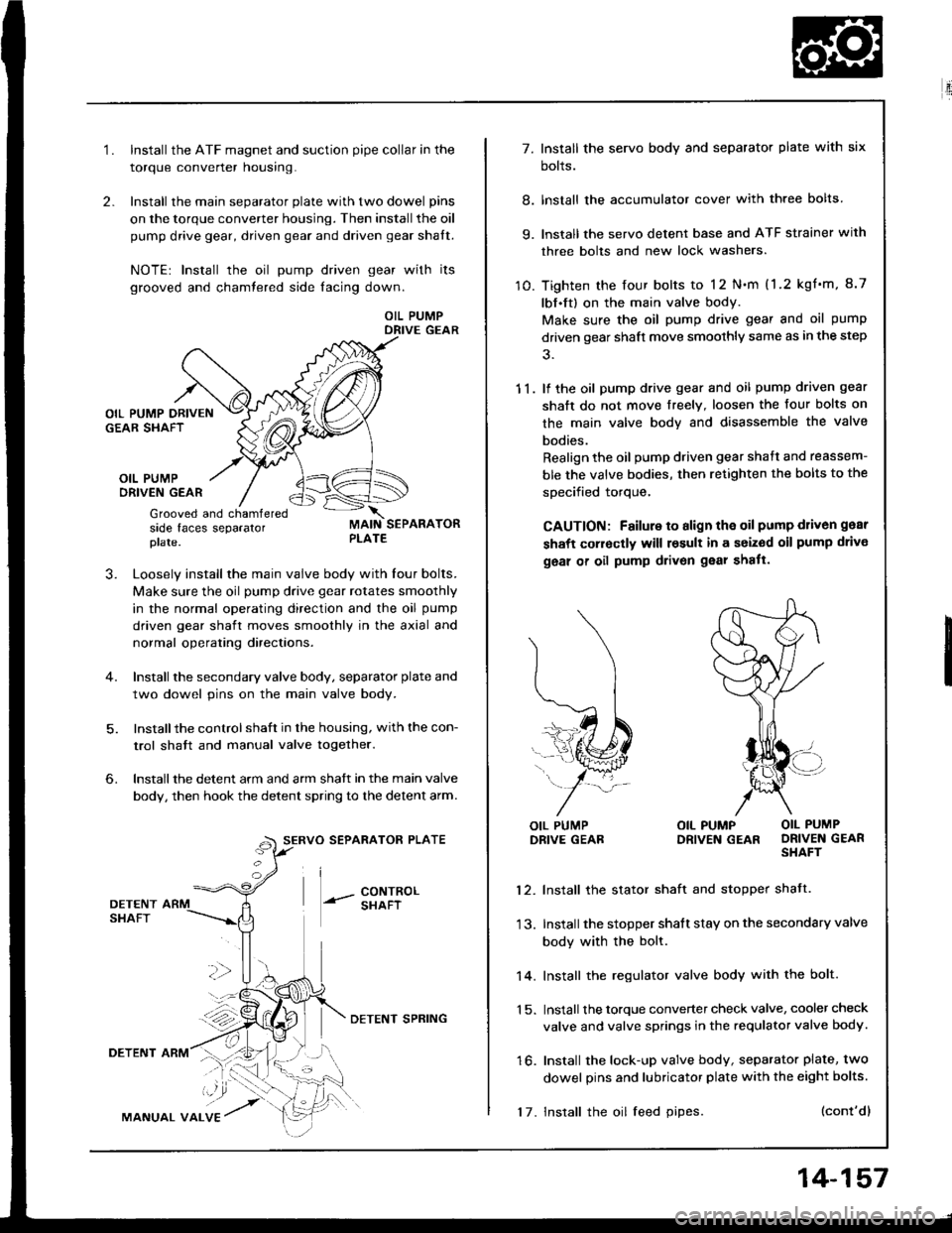
1.Install the ATF magnet and suction pipe collar in the
torque converter nousrng.
Install the main separator plate with two dowel pins
on the torque converter housing. Then install the oil
pump drive gear, driven gear and driven gear shalt.
NOTE| Install the oil pump driven gear with its
grooved and chamtered side facing down.
OIL PUMPDRIVE GEAR
OIL PUMPORIVEN GEAR
Grooved and chamferedside faces separatorplate.
J.Loosely install the main valve body with Iour bolts.
Make sure the oil pump drive gear rotates smoothly
in the normal operating direction and the oil pump
driven gear shaft moves smoothly in the axial and
normal operating directaons.
Install the secondary valve body, separator plate and
two dowel pins on the main valve body.
Installthe control shaft in the housing, with the con-
trol shatt and manual valve togelher.
Install the detent arm and arm shatt in the main valve
body, then hook the detent spring to the detent arm.
SERVO SEPARATOR PLATE
--- 8ixli"'
6.
36
DETENTSHAFT
DETENT ARM
MANUAL VALVE
DETENI SPRING
17. Install the oil feed pipes.
14-157
E'.:
7. Install the servo body and separator plate with six
bolts.
8. lnstall the accumulator cover with three bolts
9. lnstall the servo detent base and ATF strainer with
three bolts and new lock washers.
10. Tighten the four bolts to 12 N.m (1.2 kgf'm, 8.7
lbf.ft) on the main valve body.
Make sure the oil pump drive gear and oil pump
driven gear shaft move smoothly same as in the step
11. lf the oil pump drive gear and oil pump driven gear
shaft do not move freelY. loosen the four bolts on
the main valve body and disassemble the valve
bodies.
Realign the oil pump driven gear shaft and reassem-
ble the valve bodies, then retighten the bolts to the
specified torque,
CAUTION: Failure to align the oil pump d1iv6n gear
shaft corroctly will result in a seized oil pump drivo
geal of oil pump drivon gear shatt.
l\
(...l
=..�N
L,1ffi#
j-*/:
OIL PUMPDRIVE GEABOIL PUMP OIL PUMPDRIVEN GEAR DRIVEN GEARSHAFT
12. Install the stator shaft and stopper shatt.
13. Install the stopper shatt stay on the secondary valve
body with the bolt.
14. Install the regulator valve body with the bolt.
1 5. Install the torque converter check valve, cooler check
valve and valve springs in the requlator valve body.
16. Install the lock-up valve body, separator plate, two
dowel pins and lubricator plate with the eight bolts.
(cont'dl
Page 564 of 1413
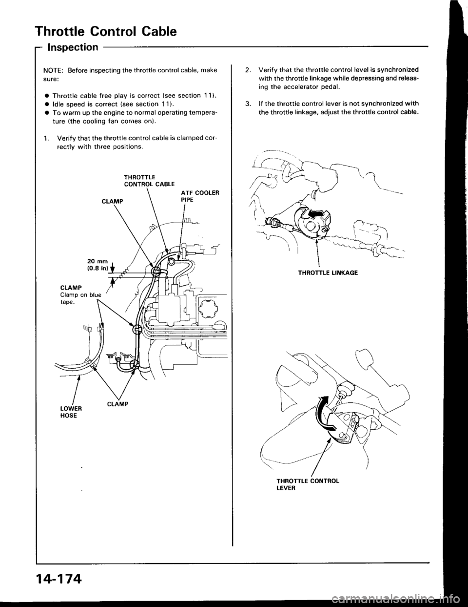
Throttle Control Cable
Inspection
NOTE: Betore inspecting the throttle control cable, make
sure:
a Throttle cable free play is correct (see section 1 1).
a ldle speed is correct (see section 1l).
a To warm up the engine to normal operating tempera-
ture {the cooling fan cor'res on)
1 . Verify that the throttle control cable is clamped cor-
rectly with three positions.
14-174
Verify that the throttle control level is synchronized
with the thronle linkage while depressing and releas-
ing the accelerator pedal.
lf the throttle control lever is not synchronized with
the throttle linkage. adjust the throttle control cable.
\
,r:
Page 566 of 1413
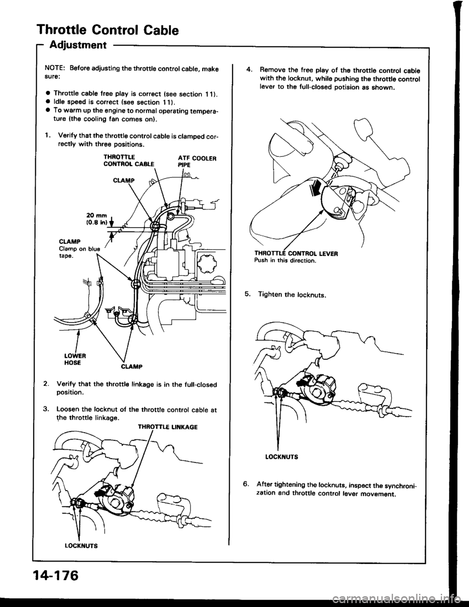
Throttle Control Cable
Adjustment
NOTE: Before adjusting ths throttle control cable, makesute:
a Throttle cable free play is correct {see section 11).a ldle speed is correct (see section 11).a To warm up the engine to normal oporsting tempera-ture {the cooling lan comes on}.
I . Verify that the throttle control c8ble is clamDed cor-rsctly with three positions.
THROTTLECOI{TROL CABLEATF COOLERPIPE
5.
CLAMP
Verify that the throttle linkage is in the full-closedposition.
Loosen the locknut of the throttle control cable atthe throttle linkage.
Clamp on blu6
THROTTLE LII{KAGE
LOCKI{UTS
14-176
4. Remove the free play of ths throttl6 control cabl€with the locknut, whils pushing thg throttlo controlleve. to the full-closed Dotision as snown,
5. Tighten the locknuts.
After tightening the locknuts, inspect the synchroni-zation and throttlg control l6ver movemenr.
Page 629 of 1413
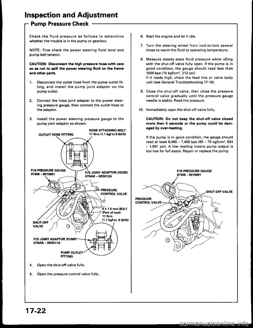
lnspection and Adjustment
Pump Pressure Check
Check the fluid pressure as follows to determine
whether the trouble is in the pump or gearbox.
NOTE: First check the power steering fluid level and
pump belt tension,
CAUnON: Dilconn€st the high pros3uro ho3s with cale
!o e3 not to spill tho powor stooring fluid on th6 lramo
lnd olhor parG.
1. Disconnect the outlet hose from the oumo outlet fit-
ting, 8nd install the pump joint adapter on the
pump outlet.
2, Connect the hose joint sdapter to the power steer-
ing pressure gauge, then connect the outlet hose to
the adaotor.
3. Instsll the power steering pressure gauge to the
pump joint adaptor as shown.
OUTLET HOSE FlTnNG
HOSE ATTACHING BOLT1l Nm11.1 kg{ m 8lbf.ftl
6 x 1.0 m.n BOLT{P!rt of tooll11 N.m11.1 kgtm,8lbf.ftl
P/S JOINT ADAPTOR IPUMPIo?NAK - SmolrA
PUMP OUTI.TTFITIING
Open the shut-off valve fully.
Open the pressure control valve fully.
17 -22
1.
Start the engine and let it idle.
Turn the stee.ing wheel from lock-to-lock several
times to warm the fluid to operating temperature.
Measure steady-state fluid pressure while idling
with the shut-off valve fully open. lf the pump is in
good condition, the gauge should read less than
1500 kpa (15 kgf/cm,,213 psi).
lf it reads high, check the feed line or valve body
unit (see General Troubleshooting l7-10).
Close the shut-off valve. then close the pressure
control valve gradually until the pressure gauge
needle is stabl6, Read the pressure.
lmmediately open the shut-off valve fully.
CAUTION: Do not keep the shut-ott valvs closod
moro thgn 5 soconds or th9 pump could b6 dam"
agod by over-h6ating,
lf the pump is in good condition, the gauge should
read at least 6.400 - 7,400 kpa (65 - 75 kgIlcm,,924- 1,067 psi). A low reading means pump output is
too low for full assist. Repair or replace the pump.
10.
P/S PRESSURE GAUGE
Page 1045 of 1413
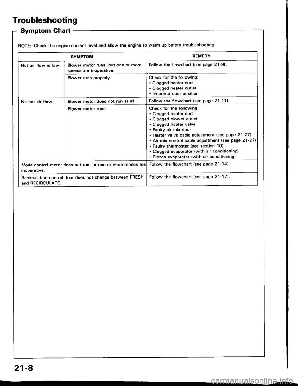
Troubleshooting
Symptom Chart
NOTE: Check the engine coolant level and allow the engine to warm up before troubleshooting.
SYMPTOMREMEDY
Hot air flow is low.Blower motor runs, but one ol more
speeds are inoperative.
Follow the tlowchart (see page 21-9).
Blower runs properly.Check for the following:. Clogged heater duct. Clogged heater outlet. Incorrect door position
No hot air JlowBlowel motor does not run at all.Follow the flowchart (see page 2l-l1l
Blower motor runs.Check for the following:. clogged heatet duct. Clogged blower outlet. Clogged heater valve. Faultv air mix door. Heater valve cable sdjustment lsee page 2'l-271
. Air mix control cable adjustment (see page 21-27)
. Faulty thermostat (see section lO)
. Clogged evaporator (with air conditioning). Frozen evaporator (with air conditioning)
Mode control motor does not run, or one or more modes are
inooerative.
Follow the flowchart (see page 21-14).
Recirculation control door does not change between FRESH
and RECIRCULATE.
Follow the flowchart (see page 21- 17).
21-A
Page 1062 of 1413
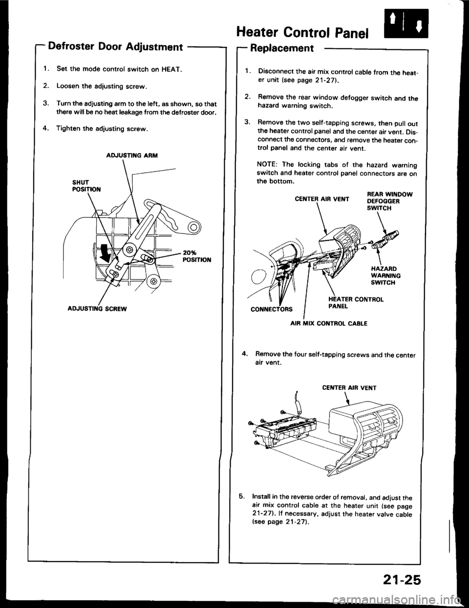
Defroster Door Adjustment
Set the mode control switch on HEAT.
Loosen the adiusting screw.
Turn the adjusting arm to the left, as shown, so that
there will be no heat leakage from the defroster door,
Tighten the sdjusting screw.4.
CE]TTER AIR VEI{T
4. Remove the four self-tapping screws and the centerair v€nt.
Install in the reverse order of removal. and adjust theair mix control cable at the heater unit lsee page21-27). lf necessary, adjust the heater valve cablelsee page 21-27).
REAR WITIDOWDEFOGGERswtTcH
Heater Control Panel
Replacement
Disconned the air mix control cable from the heat-er unit lsee page 21-271.
Remove the rear window defogger switch and thehazard warning switch.
Remove the two self-tapping screws, then pull outthe heater control panel and the center air vent. Dis-connect the connectots, and remove the heater con-trol panel and the center air vent.
NOTE: The locking tabs of the hazard warningswitch and heater control panel connectors are onthe bottom.
AD.'USTII{G ARM
ADJUSTI G SCREW
AIR MIX CONTROL CABLE
CENTEB AIR VE T
21-25
Page 1064 of 1413
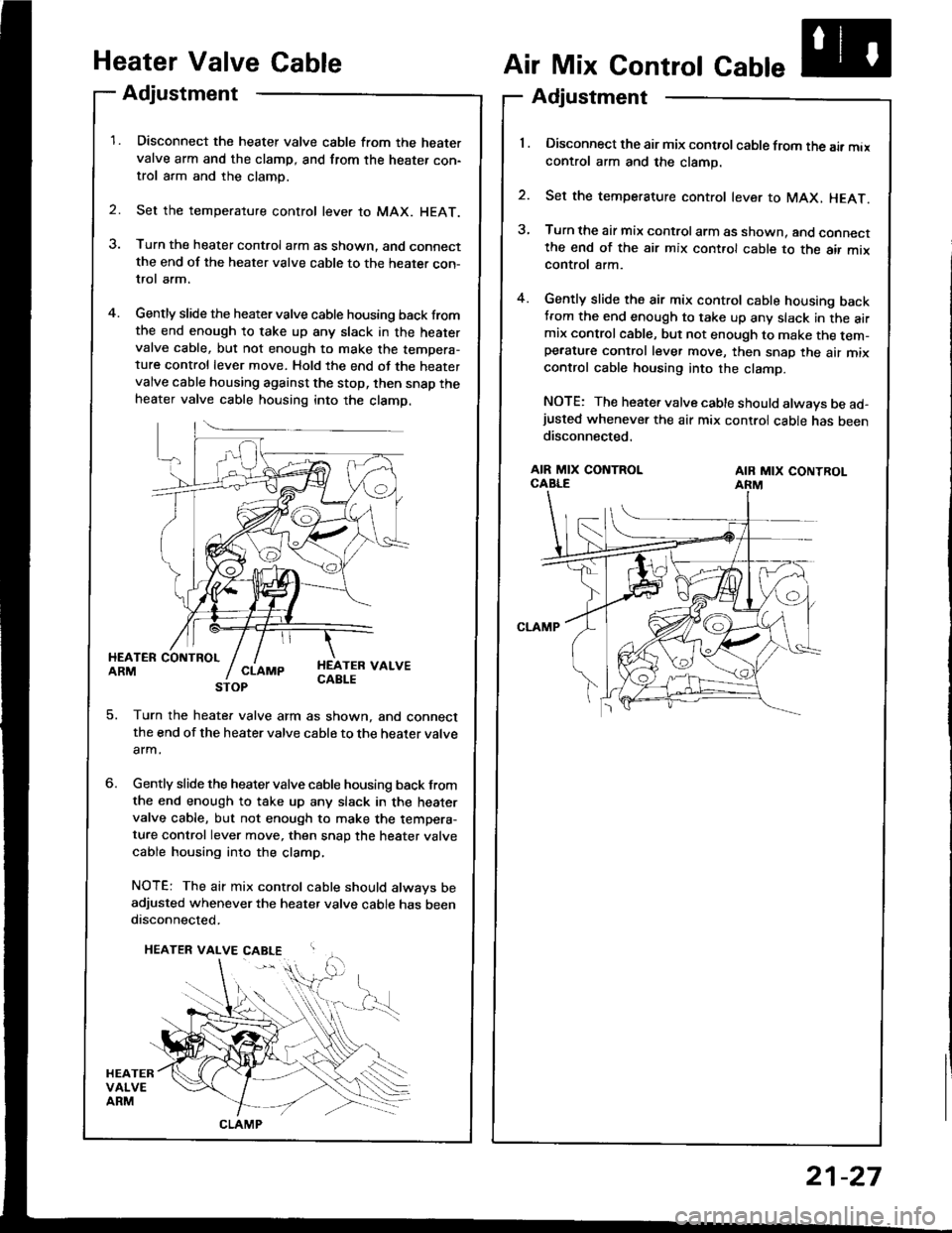
Heater Valve Gable
Adjustment
Disconnect the heater valve cable from the heatervalve arm and the clamp, and from the heater con-trol arm and the clamp.
Set the temperature control lever to MAX. HEAT.
Turn the heater control arm as shown. and connectthe end of the heater valve cable to the heater con-trol arm.
Gently slide the heater valve cable housing back fromthe end enough to take up any slack in the heatervalve cable, but not enough to make the tempera-ture control lever move. Hold the end of the heatervalve cable housing against the stop, then snap theheater valve cable housing into the clamp.
2.
Air Mix Control Cable
Adjustment
'l . Disconnect the air mix control cable from the air maxcontrol arm and the clamp.
2. Set the temperature control lever to MAX, HEAT.
3, Turn the air mix control arm as shown. and connectthe end of the air mix cont.ol cable to the air mixcontrol arm.
4. Gently slide the air mix control cable housing backtrom the end enough to take up any slack in the airmix controlcable, but not enough to make the tem-pe.ature control lever move, then snap the air mixcontrol cable housing into the clamp.
NOTE: The heater valve cable should always be ad-justed whenever the air mix control cable has beendisconnected.
HEATER COIITBOLARMHEATEB VALVECABLE
AIR MIX CONTROLCABLEAIB MIX CONTROLARM
5. Turn the heate. valve arm as shown, and connectthe end of the heater valve cable to the heater valve
arm.
Gently slide the heater valve cable housing back from
the end enough to take up any slack in the heatervalve cable, but not enough to make the tempera-ture control lever move, then snap the heater valve
cable housing into the clamp,
NOTE: The air mix control cable should always beadjusted whenever the heater valve cable has beendisconnected.
CLAMP
21-27