g551 HONDA INTEGRA 1994 4.G Workshop Manual
[x] Cancel search | Manufacturer: HONDA, Model Year: 1994, Model line: INTEGRA, Model: HONDA INTEGRA 1994 4.GPages: 1413, PDF Size: 37.94 MB
Page 1119 of 1413

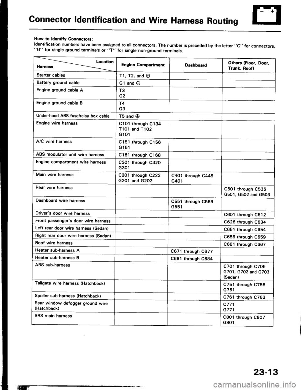
Connector ldentification and Wire Harness Routing
How to ldentity ConnoctolS:
ldentification numbers have been assigned to all connectors. The number is preceded by the letter ,,C,, for connecrors,"G" for single ground terminals ot "f" hr single non-ground terminals.
Location
HamessEngino CompartmontDarhboardOthors (Floor, Door,
Trunk, Rootl
Starter cablesT1, T2, and (E
Battery ground cableG1 and O
Engine ground cable AT3
Engine ground cable BT4
G3
Under-hood ABS fuse/relav box cableT5 and (D
Engine wire harnessC101 through C134
Tl Ol and T102
G 101
A/C wire harnessCl 5'l through C156
G151
ABS modulator unit wir€ harnessC161 through C168
Engine companment wire ha.nessC3O'l through C32O
G301
Main wire hatnessC2O1 through C223
G2Ol and G2O2
C4O1 through C449
G401
Rear wire harnessC501 through C536
G501, G502 and G5O3
DashboSrd wire harnessC551 through C569
G551
Driver's door wire harnessC601 through C612
Front passenger's door wire harnessC626 through C634
Left rear door wire harness (Sedan)C651 through C654
Right rear door wire harness (Sedan)C656 through C659
Roof wire harnessC661 through C667
Heater sub-harness AC671 through C677
Heater sub-hatness BC681 through C684
ABS sub-harnessC7O1 through C7O6
G7O1, G702 and G703(Sedan)
Tailgate wire harness (Hatchback)C751 through C756
Spoiler sub-ha.ness (Hatchback)C761 through C763
Rear window defogger ground wire(Hatchback)c77'l
G771
SRS main harnessC8O1 through C8O7
G801
23-13
Page 1254 of 1413

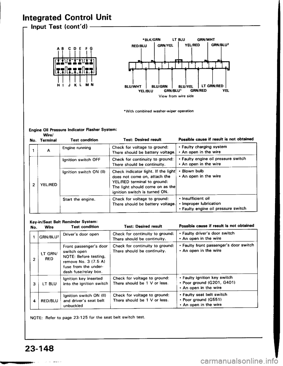
Integrated Control Unit
Input Test (cont'd)
Engine Oil Pressure Indicator Flashal System:
Wire/
rWith combined washeFwipot operation
Test: Desired resultPossiblo c€use if r6rult is not obtainodNo. TelminalTsst condition
M
1Engine runningCheck for voltage to ground:
There should be battery voltage
. Faulty charging system. An oDen in the wire
YEL/RED
lgnition switch oFFCheck for continuity to gtound:
There should be continuitv.
. Faulty engine oil ptessure switch
. An oDen in the wire
lgnition switch ON (ll)Check indicator light. lf the light
does not come on, Sttach the
YEL/RED terminal to ground:
The light should come on as the
ignition switch is turned ON.
. Blown bulb. An open in the ware
Start the engine.Check for voltage to ground:
There should be battery voltage
Insufficient oil
lmproper lubrication
Faulty engine oil pressure switch
Key-in/Seat Bolt Reminder Systam:
No. WilaTest condition
NOTE: Refer to page 23-125 for the seat belt switch test.
Test: Dosired lesuhPossible causo if resuh is not obtainod
23-148'
GRN/BLU'Driver's door openCheck for continuity to ground;
There should be continuitv.
. Faulty driver's door switch
. An ooen in the wire
LT GRN/
RED
Front passenger's door
switch open
NOTE: Betore testing,
remove No. 3 (7.5 A)
tuse from the under-
dash fuse/relay box.
Check tor continuity to ground:
There should be continuitv.
. Faulty lront passenger's door switch
. An ooen in the wire
LT BLU
lgnition key inserted
into the ignition switch
Check for voltage to ground:
There should be 1 V or less.
Faulty ignition key switch
Poor ground (G201 , G401)
An ooen in the wite
RED/BLU
lgnition switch ON (ll)
and driver's seat belt
unbuckled
Check lor voltage to ground:
There should be 1 V or less.
Faulty seat belt switch
Poor ground {G551)
An open in the wire
;.rqFft,
Page 1298 of 1413
![HONDA INTEGRA 1994 4.G Workshop Manual Terminals
Connects to
\
*i,.,-terlll
FO] ANTENNA LEADA
TI!NM[IAL
A9---------+A16
Stereo Sound System
Stereo Radio/Cassette PlayerFront Speaker/Tweeter
Replacement
Front Spoakor:
1. Carefully pry out t HONDA INTEGRA 1994 4.G Workshop Manual Terminals
Connects to
\
*i,.,-terlll
FO] ANTENNA LEADA
TI!NM[IAL
A9---------+A16
Stereo Sound System
Stereo Radio/Cassette PlayerFront Speaker/Tweeter
Replacement
Front Spoakor:
1. Carefully pry out t](/img/13/6067/w960_6067-1297.png)
Terminals
Connects to
\
*i,.,-terlll
FO] ANTENNA LEADA
TI!NM[IAL
A9---------+A16
Stereo Sound System
Stereo Radio/Cassette PlayerFront Speaker/Tweeter
Replacement
Front Spoakor:
1. Carefully pry out the speaker cover.
2. Remove the three screws, then disconnect the 2-P
connector Jrom the speaker, and remove the
speaker.
2.P CONNECTOR
Twootor:
1. Remove the door panel and disconnect the tweeter
2-P connector.
2. Remove the two screws, then remove the tweeter
ano covet.
r^l
It
\7
rSPEAKERCOVER
A1RED/GRNFront passenger's door speaker O
A2BLU/GRNDriver's door speaker @
A3RED/BLKLights-on signal
A4WHT/8LUConstant power {Tuning memory)
A5YEL/REDACC (Main stereo powe. supplyl
A6YEL/GRNRadio switched power (To antenna)
A7BLU/YELLeft rear speaker O
A8RED/YELRight rear speaker @
A9BRN/BLKFront passenger's door speaker O
A10GRY/BLKDriver's door speaker O
A lnot used)
412(not used)
A13(not usedl
A14BLKGround (G551)
Al5GRY/WHTLeft rear speaker O
A16BRNAA/HTRight rear speaker e
23-192
IFrIFit