brake sensor HONDA INTEGRA 1994 4.G Workshop Manual
[x] Cancel search | Manufacturer: HONDA, Model Year: 1994, Model line: INTEGRA, Model: HONDA INTEGRA 1994 4.GPages: 1413, PDF Size: 37.94 MB
Page 79 of 1413
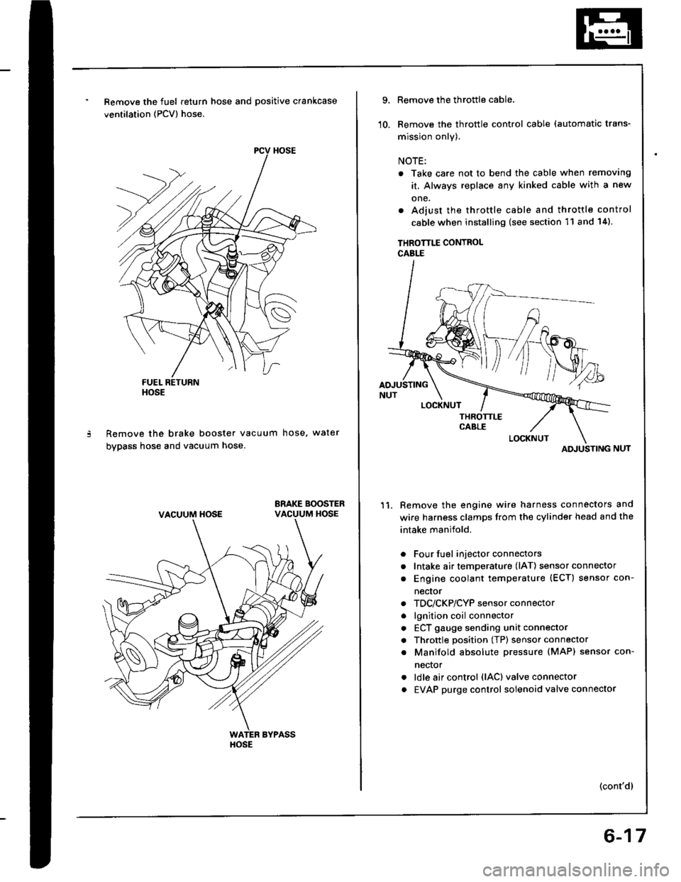
Remove the fuel return hose and positive crankcase
ventilation (PCV) hose.
Remove the brake booster vacuum hose, water
bypass hose and vacuum hose.
ERAKE BOOSTERVACUUM HOSE
HOSE
VACUUM HOSE
HOSE
9.
10.
Remove the throttle cable.
Remove the throttle control cable (automatic trans-
mission only).
NOTE:
. Take care not to bend the cable when removing
it. Always replace any kinked cable with a new
one.
. Adjust the throttle cable and throttle control
cable when installing (see section 11 and 14).
THROTTLE CONTROLCABLE
Remove the engine wire harness connectors and
wire harness clamps trom the cylinder head and the
intake manifold.
Four fuel injector connectors
Intake air temperature (lAT) sensor connector
Engine coolant temperature (ECT) sensor con-
necror
TDC/CKP/CYP sensor connector
lgnition coil connector
ECT gauge sending unit connector
Throttle position (TP) sensor connector
Manifold absolute Dressure (MAP) sensor con-
nector
ldle air control (lAC) valve connector
EVAP purge control solenoid valve connector
11.
a
a
a
a
a
a
a
a
a
(cont'dl
ATI'USTING
6-17
Page 194 of 1413
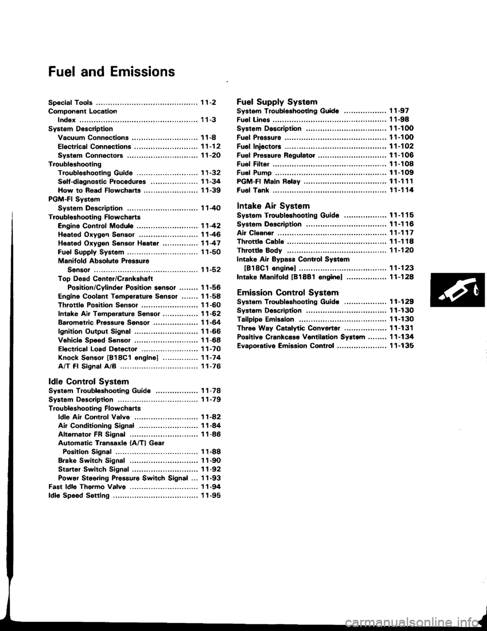
Fuel and Emissions
Spocial Tools ................ 1 1-2
Compon€nt Location
lndex ................. ...... 11-3
System Description
Vacuum Connectiona .......,.................... 1 1 -8
Efectrical Connections ....,.,.,......,...,,.....,'11-12
Syst€m Connectors ...,...,.................-.--. 11-2O
T.oubloshooting
Troubleshooting Guido .......................... 1 1-32
Self -diagnostic Procedures .,..,............... 1 1 -34
How to Road Flowcharts ...................,... 11-39
PGM-Fl System
Systom Description .............................. 1 l-4O
Troubleshooting Flowcharts
Engine Control Moduls ............... ........... 1 1 -42
Heated Oxygon Sensor ......,.................. 1 1-46
Heated Oxyg€n Sonsol Heatel .....,......... 1 1 -47
Fuel Supply System ..............-............... 1 1-50
Manitold Absolute Pressure
Ssnsor ............................................ 1 1-52
Top D6ad Cente./Crankshatr
Position/Cylindor Position sonsor ........ 1 1 -56
Engine Coolant Tempsrature Sonsor ....... 11-58
Throttlo Position Sonsor ........,..,,........... 1 1-60
Intake Air Temperaturs Sensor ............... 11-62
Baromet c Prsssuro Sensor ......,...,...,..,. 11-64
lgnition Output Signal ........................... 1 1 -66
Vehicle Spe€d Sensor ........................... 1 1 -68
Electdcal Load Dotector ....,...,..........,.... 1 1 -7O
Knock Sensor [818C1 engine] ............... 11-74
A/T Fl Signal A/B ................................. 1 1-76
ldle Contlol System
System Troubleshooting Guide .................. 1 1 -78
Systom Description ........ 11-79
Troubloshooting Flowchans
ldl€ Ail Control Valve ........................... 1 1 -82
Ail Conditioning Signal ......................... 1 1 -84
Altemator FR Signal ............................. 1 1 -86
Automatic Transaxle (A/T) Gear
Position Signal ......... 11-88
Brake Switch Signal ............................. 1 1 -9O
Startel Switch Signal ............................ 11-92
Power Steering Pressure Switch Signal ... 11-93
Fast ldle Thermo Valve ...................,......... 1 1 -94
ldls Speed S€tting .................................... 1 1 -95
Fuel Supply System
Systam Tloubloshooting Guid. .................. 1 1 -97
Fuol Linos ...................... 1'l -98
System Description ........ 11-100
Fuol Prassure ................. 11-100
Fu6l Ini6ctors ................. 11-102
Fuel Pressure Ragulato. .,. 11-106
Fuel Filter ...................... 11-108
Fual Pump ..................... 11-109
PGM-Fl Main F6lay ................................... 1 1"1 1 1
Fuel Tank ...................... t 1-114
Intake Air System
System Troubloshooting Guido .................. 1 1 -1 1 5
Systom Dascription ........ 11-116
Air Clean€r .................... 11-117
Throttls Cable ................'11-118
Throttl8 Body ................ 11-120
lntake Air Bypass Cont.ol Systsm
[B18Cl enginal .,......... 11-123
Intake Manilold [B1881 onginol ................. 11-128
Emission Control System
Systsm Troubleshooting Guido .................. 1 1 -1 29
Systam Doscription ........ 11-130
Tailpips Emission ........... 11-130
Thrae Way Catalytic Convortor ...,...,........., 11-131
Positiva CrankcaEo V6ntilation Systcm .,....., 11-134
Evaporativo Emission Contro|,..,..,.,.,,.,,..,.., 1 1-135
Page 232 of 1413
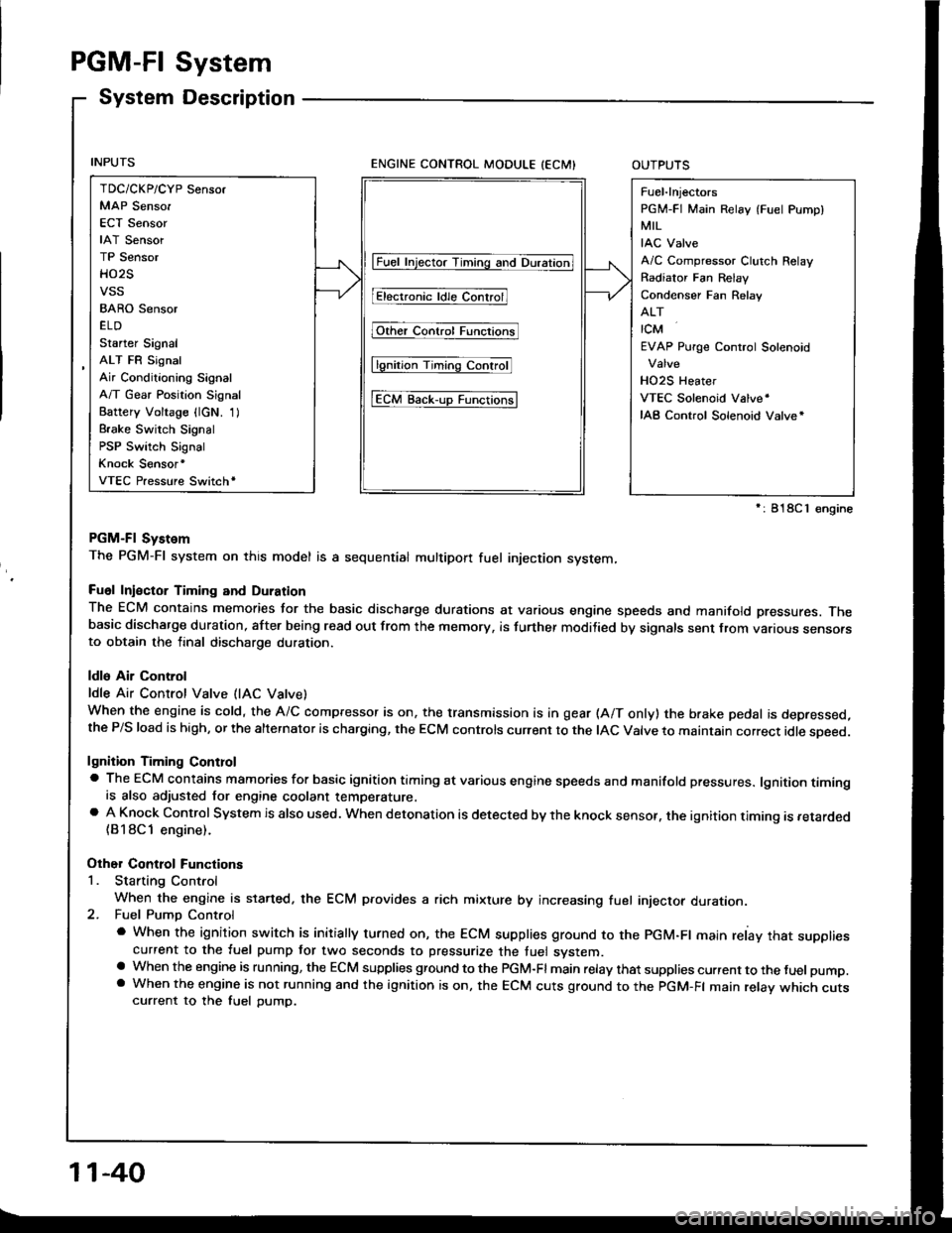
PGM-FI System
System Description
ENGINE CONTROL MODULE (ECMIOUTPUTS
PGM-Fl System
The PGM-Fl system on this model is a sequential multipon fuel injection system,
Fuol Iniector Timing and Duration
The ECM contains memories tor the basic discharge durations at various engine speeds and manifold pressures. Thebasic discharge duration, after being read out from the memory, is turther modilied by signals sent from vanous sensofsto obtain the final discharge duration.
ldle Air Control
ldle Air Control Valve (lAC Vatve)
When the engine is cold, the A/C compressor is on, the transmission is in gear (A/T only) the brake pedal is depressed,the P/S load is high, or the alternalor is charging, the ECM controls current to the IAC Valve to maintain correct idle soeed.
lgnition Timing Controla The ECM contains mamories for basic ignition timing at various engine speeds and manifold pressures. lgnition timingis also adjusted for engine coolant temperature.a A Knock Control System is also used. when detonation is detected by the knock sensof. the ignition timing is retarded(B18Cl engine).
Other Control Functions
1. Starting Control
When the engine is started. the ECM provides a rich mixture by increasing fuel injector duration.2. Fuel Pump Control
a When the ignition switch is initially turned on, the ECM supplies ground to the PGM-Fl main relay that suppliescurrent to the fuel pump tor two seconds to pressurize the tuel system.a When the engine is running, the ECM supplies gfound to the PGM-Fl main relay that supplies current to the fuel pump.a When the engine is not running and the ignition is on, the ECM cuts ground to the PGM-FI main relav which cutscurrent to the fuel pump.
TDC/CKP/CYP Sensor
MAP Senso.
ECT Sensor
IAT Sensor
TP Sensor
HO2S
vss
BARO Sensor
ELD
Starter Signal
ALT FR Signal
Air Conditioning Signal
A/T Gear Position Signal
Battery Voltage {lcN. 1)
Brake Switch Signal
PSP Switch Signal
Knock Sensor'
VTEC Pressure Switchr
Fuel-lnjectors
PGM-FI Main Relay (Fuel Pump)
MIL
IAC Valve
A/C Compressor Clutch Relay
Radiator Fan Relav
Condenser Fan Relav
ALT
rcM
EVAP Purge Control Solenoid
HO2S Heater
VTEC Solenoid Valve'
IAB Control Solenoid Valve*
lFuet tnjector Timing and Duration]
I Electr..l"ldle Contr;il
Fit'e' contr; Funcrfit
l6tio; Ttntrlg c..trol
tEcM aack-,rp Functiorlsl
': 818C 1 €ngine
11-40
Page 346 of 1413
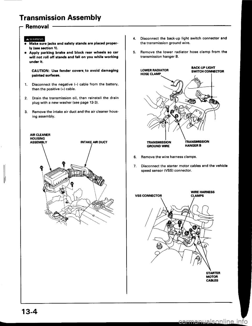
Transmission Assembly
Removal
Mskc aurs iack! and safoty Etands aro placod proper-
ly lsl8 saqtion 1|.
Apply parking brake tnd block rear whccl! to car
will not roll ofl stand3 and f.ll on you while wotking
undrr it.
CAUTION: Use tondcr coyar3. to avoid drmlging
plintsd 3qrfaca3,
Disconn€ct the negative {-) cable from the battery,
then the positive (+) cable.
Drain the transmission oil, then reinstall the drain
plug with a new washer (see page 13-3),
Remove the intake air duct and the air cleaner hous-
ing assembly,
AIR CITANERHOUSING
13-4
4. Disconnect the back-up light switch connoctor and
the transmission ground wir€.
5, Remove the lower radiator hose clamp trom ths
transmission hanger B.
BACK.UP LGHTsuTcH cot{t{EcToR
lnaNsMttistoNGROUND WIRE
tnaNsi ssloNHANGEB B
o.
1.
R€move the wire harness clamPs.
Disconnect the stsrt€r motor cables and the vahicla
soeed sensor (VSS) connector.
VSS OONNECTOR
Page 393 of 1413
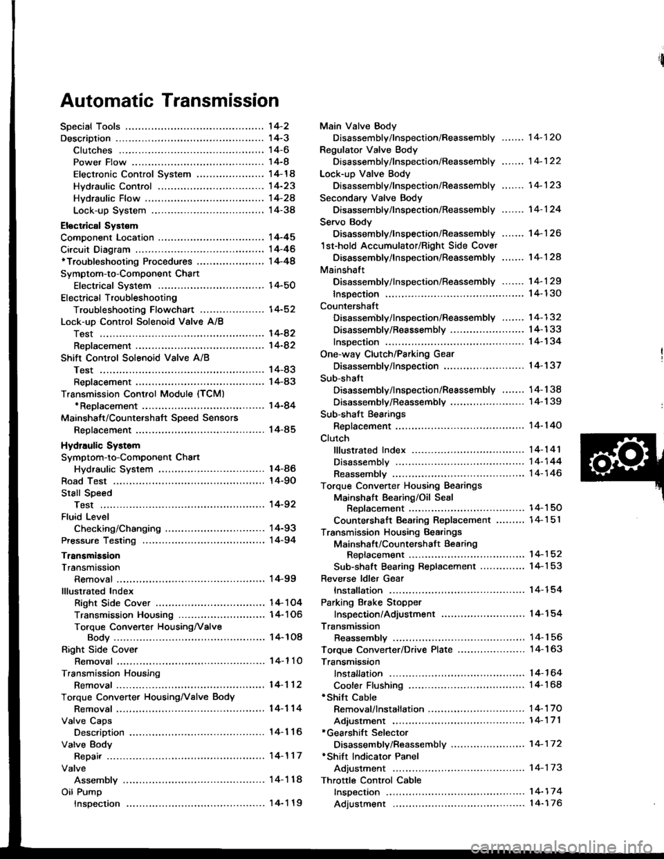
Automatic Transmission
'l4-2
14-3't 4-6
14-8
14-14
14-23
Hvdraulic Flow ...--...... 14-24
Lock-up System ........ 14-38
Eloctrical Systom
Component Location ............,...,................ I 4-45
Circuit Diagram ............. 14-46'Troubleshooting Procedures ........,..........., l4-48
Symptom-to-Component Chart
Electrical System ...... 14-50
Electrical Troubleshooting
Troubleshooting Flowchart .................... 14-52
Lock-uo Control Solenoid Valve A/8
Test .................. --.... \4-82
ReDlacement ,...,...,..,. 14-82
Shift Control Solenoid Vslve A/B
Test .................. ...... 14-83
Reolacement .............. 14-83
Transmission Control Module (TCM)*ReDlacement ........... 14-84
Mainshalt/CountershaJt SDeed Sensors
Reolacement ............. 14-85
Hydraulic Systom
Symptom-to-Component Chart
Hydraulic System
Road Test
Slall Speed
Test ..................
Fluid Level
Checking/Changing
Pressu.e Testing
Transmission
Transmission
Removal ............. ...... 14-99
lllustrated Index
Right Side Cover .................................. 1 4- 1 04
Transmission Housin9 ..................,,....... I 4-1 06
Torque Converter HousingNalve
Body .................. ... 14- 1O8
Right Side Cover
Removal ............. ...... 14-110
Transmission Housing
Removal ............. .-..-. 14-112
Torque Convener HousingNalve Body
Removal ............. ...... 14-114
Valve Caps
Description ................ 14-116
Valve Body
Repair ................ ...-.. 14-117
Valve
Assembly ...........
Oil Pump
Main Valve Body
Disassembly/lnspection/Reassembly
Regulator Valve Body
Disassembly/lnspection/Reassembly
Lock-up Valve Body
Disassembly/lnspection/Reassembly .......
Secondary Valve Body
Disassembly/lnspection/Reassembly .......
Servo Body
Disassembly/lnspection/Reassembly .......
1st-hold Accumulator/Right Side Covet
Oisassembly/lnspection/Reassembly .,..,..
Mainshaft
Disassembly/lnspection/Reassembly -.. -... 1 4- 1 29
lnsDection ................. 14- 130
Countershaft
Disassembly/lnspection/Reassembly ....... 14-132
Disassembly/Reassembly ....................... 1 4-1 33
lnsDection ................. 14-134
One-way Clutch/Parking Gear
Disassembly/lnspection .................... -.. -. 1 4-137
Sub-shaft
Disassembly/lnspection/Reassembly ....... 14-138
Disassemblv/Reassemblv ....................... 1 4-1 39
Sub-shaft Bearings
Replacement ............. l4-140
Clutch
fllustrated lndex ................. -..-...-.......... 14-1 41
Disassembly ,,,.,,........ 14-144
Reassembly .............. 14-146
Torque Converter Housing Bearings
Mainshaft Bearing/Oil Seal
Reolacement ......... 14-1 50
Countershaft Bearing Replacement .......,, 14-1 5l
Transmission Housing Bearings
Mainshsft/Countershaft Bearing
Repfacement ...-..-..14-152
Sub-shaft Bearing Replacement .............. 1 4-1 53
Reve.se ldler Gear
lnstallation ................ 14-154
Parking Brake Stopper
lnspection/Adjustment ..........................'14-'154
Transmission
Reassemblv .............,. .14_156
Toroue Converter/Drive Plate ..,..,............... 1 4- 1 63
Transmission
14-120
14-122
14-123
14-124
14-126
14-124
14-86
14-90
't4-92
14-93
14-94
lnstallation
Cooler Flushing'Shitt Cable
Removal/lnstallation ..............................
Adiustment ...-..-......-. 14-'171*Gearshift Selector
Disassembly/Reassembly .....................,. 1 4-17 2*Shift Indicator Panel
Adjustment -..........-...14-173
Throttle Control Cable
fnspection .......,..,...... 14-17 4
Adjustment .............. 14-176
14-164
14-168
14-'t 7 0
Inspection
Page 412 of 1413
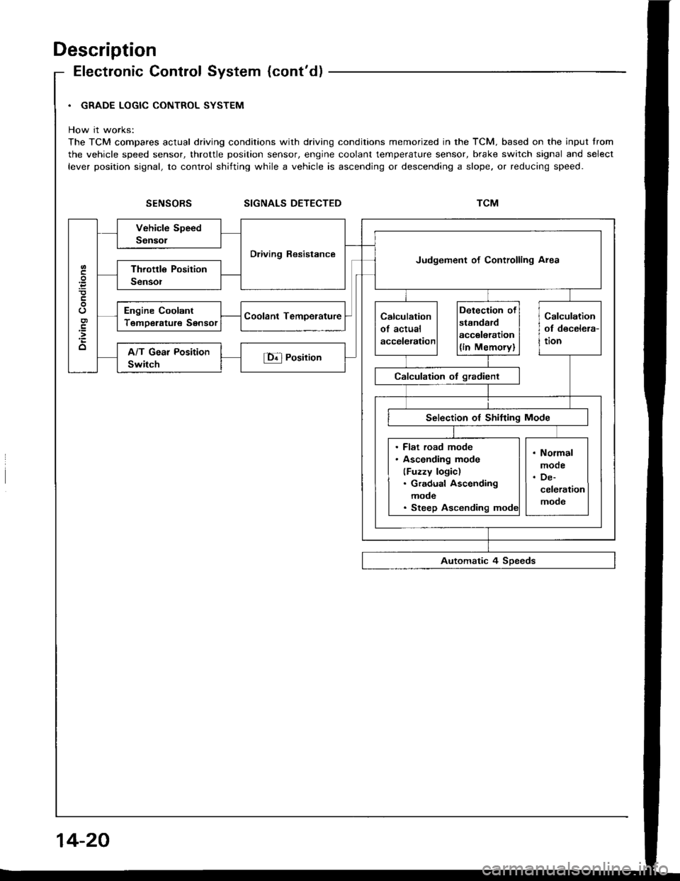
Description
Electronic Control System (cont'd)
. GRADE LOGIC CONTROL SYSTEM
How it works:
The TCM compares actual driving conditions with driving conditions memorized in the TCM. based on the input trom
the vehicle speed sensor, throttle position sensor, engine coolant temperature sensor, brake switch signal and select
lever position signal, to control shifting while a vehicle is ascending or descending a slope. or reducing speed.
SIGNALS DETECTED
Dliving ResistanceJudgement of Controlling Area
Engine Coolant
TemDerature Sensor
. Flat road mode. Asconding mode
(Fuzzy logic). Gradual Ascending
mode. Steep Ascending
14-20
Page 443 of 1413
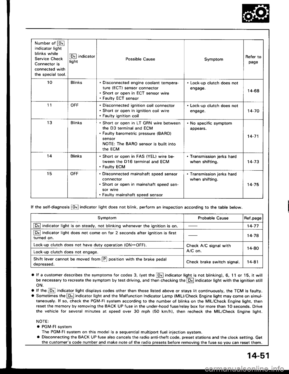
Number of @indicator light
blinks while
Service Check
Connector is
connected with
the special tool.
@ indicator
lightPossible CauseSymptomRefer to
page
'loBlinksDisconnected engine coolant tempera-
rure (ECT) sensor connector
Short or open in ECT sensor wire
Faulty ECT sensor
Lock-up clutch does not
engage.14-68
1lOFFDisconnected ignition coil connector
Short or open in ignition coil wire
Faulty ignition coil
. Lock-up clutch does not
engage.'t 4-7 0
13Blinks. Shon or open in LT GRN wire between
the D3 terminal and ECM. Faulty barometric pressure {BARO)
sensor
NOTE: The BARO sensor is built into
the ECM
. No specific symptom
appears.
14-7 1
14Blinks. Short of open in FAS {YEL} wire be-
tween the D16 terminal and ECM. Faulty ECM
. Transmission jerks hard
when shitting.
't5OFFDisconnected mainshaft speed sensor
connecror
Short or open in mainshaft speed sen-
sor wire
Faulty mainshaft speed sensor
. Transmission jerks hard
when shifting.
14-75
SymptomProbable CauseRet.page
LQ! indicator light is on steady, not blinking whenever the ignition is on.14-77
[Q3] indicator light does not come on for 2 seconds after ignition is first
turned on.14-78
Lock-up clutch does not have duty operation (ON-OFFI.Check A/C signal with
A/C on.14-80Lock-up clutch does not engage.
Shitt leve. cannot be moved lrom @ position with the brake pedal
depressed.Check brake switch signal,14-41
It the self-diagnosis LQ4 indicator light does not blink, perform an inspection according to the table below.
a lf a customer describes the symptoms for codes 3, (yet the LQ! indicator light is not blinkingl, 6, 1 1 or 15, it will
be necessa.y to recreate the symptom by test driving. and then checking the @ indicator light with the ignition still
oN.
e lt ttre @ indicator light displays codes olher than those listed above or stays lit continuously, the TCM is faulty.. Sometimes the Lqd indicator light and the Malfunction Indicator Lamp (MlL)/Check Engine light may come on simul-taneously. lf so, check the PGM-Fl system according to the numbe. of blinks on the MIL/Check Engine light. thenreset the memory by removing the BACK UP fuse in the unde.-hood fuse/relay box for more than 1O seconds. Drive
the vehicle for several minutes at speed over 30 mph (5O km/h), then recheck the MIL/Check Engine light.
NOTE:
. PGM-FI system
The PGM-Fl system on this model is a sequential multiport fuel injection system.a Disconnecting the BACK UP luse also cancels the radio anti-theft code. preset stations and the clock setting. Get
the fuse so vou can reset them.the customer's code number and make note ot the radio
14-51
Page 449 of 1413
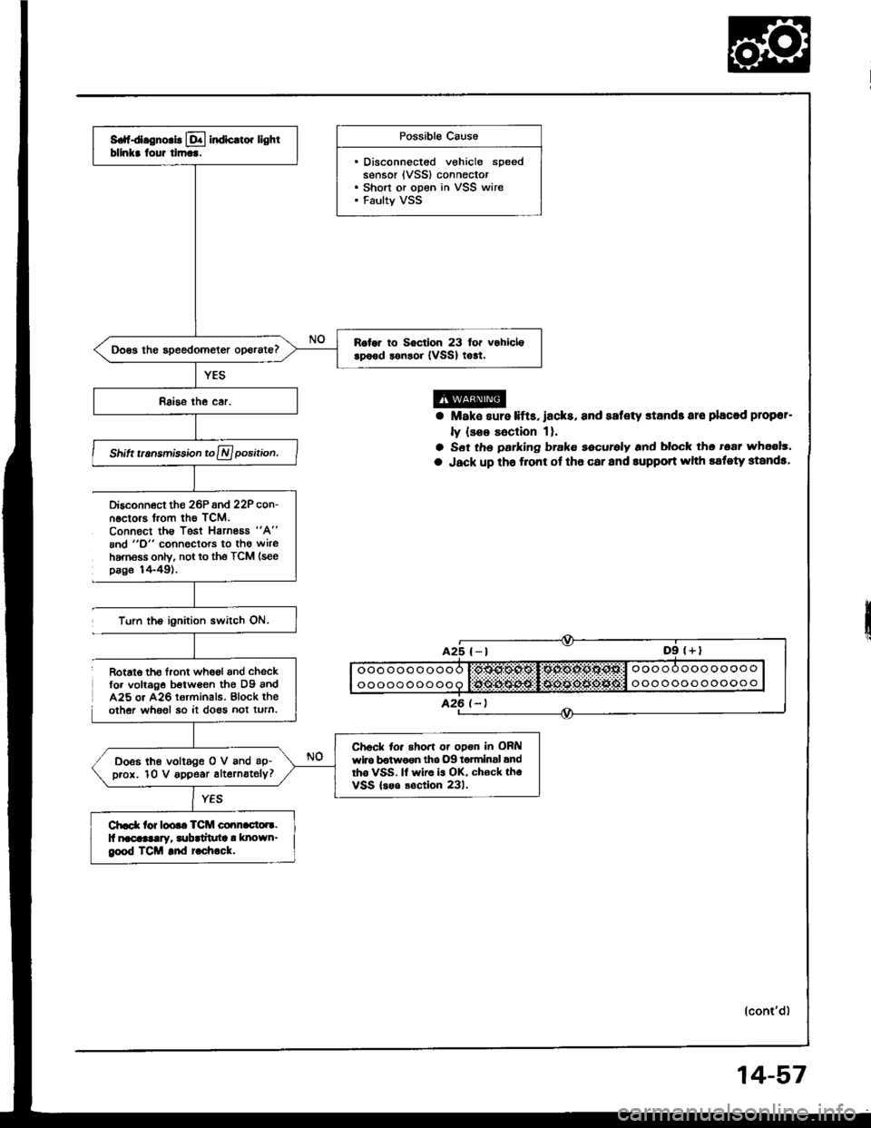
S. d.gno.b lql indic.to. lightbllnkr tour tlm...
R.lor to Soctlon 23 for vohiclerpood lonsoi {vSSl to!t.
Shift t.nsmisiion to A position.
Ch6ck to. shoft or opon in OFilwlro b€twoen tho .)9 t6tminsl andrho VSS. lf wiro is OK, ch€ck thoVSS lsoo soction 231.
Doss lhe voltage O V and ap-p.ox. 10 V appe.r alternately?
Ch.d( tor loo.. TCM co.!n.cto.r.ll nacaaalay, lubrtituta ! known_geod TCM and t chock.
Possible Caus6
. Disconnectsd vehicle speedsensor {VSS} connector. Short or open in VSS wire. Faulty VSS
Disconn6ct the 26Pand 22P con-n.ctors trom th€ TCM.Connect ths Tgst Harnoas "A"
8nd "O" connectors to tho wireharnsss only, not to the TCM (see
page 1+49).
Turn the ignilion switch ON.
a Mak€ sure lifts,lacks, and safety stands aro placod plopor-
ly {see Eaclion 1}.
a S6t th6 parking brake eecurely and block tho tear wh6ol3'
a Jack up tho f.ont ot tho car and rupport whh sstoty standa.
(cont'd)
Rotat€ th€ tront wh6ol and chsckfo. volt6g€ botwean the D9 andA25 o. A26 terminals. Block theother whaol 30 it do€s not turn.
14-57
Page 482 of 1413
![HONDA INTEGRA 1994 4.G Workshop Manual Road Test
NOTE: Warm up the engine to operating temperature (the cooling fan comes on).
1 Apply parking brake and block th€ wheels. Start the engine, them move the selector lever to E] position whil HONDA INTEGRA 1994 4.G Workshop Manual Road Test
NOTE: Warm up the engine to operating temperature (the cooling fan comes on).
1 Apply parking brake and block th€ wheels. Start the engine, them move the selector lever to E] position whil](/img/13/6067/w960_6067-481.png)
Road Test
NOTE: Warm up the engine to operating temperature (the cooling fan comes on).
1 Apply parking brake and block th€ wheels. Start the engine, them move the selector lever to E] position whiledepressing the brake pedal. Depress the accelerator pedal, and release it suddenly. The engine should not stall,
2. Repeat same test in @ position.
3. Shift the selecto. lever to E position, and chock that the shift points occur at approximate speeds shown. Alsocheck fof abnormal noise and clutch slippage.
NOTE: Throttle position sensor voltage fepresents the throttle opening.
- 1 . Connect the Test Harness between the ECM and connector (see section 1 1).-2. Setthe digital multimeter to check voltage between D1 1{+)terminal and D22 { - ) terminal for the throttle Dosi-tion sensor.
TESTHARI{ESSOTLAJ_PT3OlOA
DIGITAL MULTIMETERCommarcially avsilablo o.KS-AHM-32-OO3
011 {+oooooooooooooooooooooooooooooooooooooooooooooooooooooooooooooooooooooooooooo
14-90
Page 483 of 1413
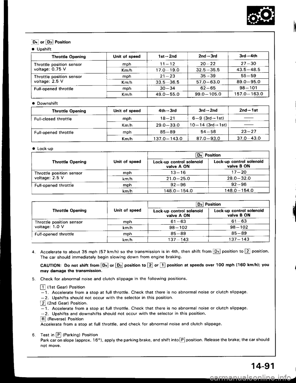
Throftle OpeningUnit of spe6dl st- 2nd2nd-3rd3rd-4th
Throttle position sensorvoltage: O.7 5 V
mph20-2227,30
Km/h17,O 19.O32.5 - 35.543.5-48.5
Throttle position sensorvoltage: 2.5 V
mpn
Km/h33.5 - 36.557.O-63.O89.O-95.O
Full-opened throttlemph30- 3462-6598- 101
Km/h49.O- 55.O99.O- 105.O1 57.O- 163.O
@ or @ Position
. Upshitt
Downshift
LOCK-Up
4. Accelerate to about 35 mph {57 km/h) so the transmission is in 4th, then shift from @ Oosition to E position.
The car should immediately begin slowing down from engine braking.
CAUTION: Do not shift from @ or @ position to @ of E position at speeds over 1OO mph (160 km/h); you
may damage the tlansmission,
5. Check lor abnormal noise and clutch slippage in the following positions.
E (1st Gear) Position- 1 . Accelerate from a stop at full throttle. Check that there is no abno.mal noise or clutch slippage.
-2. Upshifts should not occur with the selector in this position
E (2nd cear) Position.- 1 . Accelerate from a stop at full throttle. Check that there is no abnormal noise or clutch slippage.-2. Upshitts and downshitts should not occur with the selector in this position.
E {Reverse) Position
Accelerate from a stop at full throttle, and check for abnormal noise and clutch slippage.
6. Test in E {Parking) Position
Park car on slope (approx. 1 6o ), apply the parking brake, and shift into LE position. Release the brake; the car should
not move.
i
Throttle Op€ningUnit ot speed4th- 3rd3rd - 2nd2nd- l Et
Full-closed throttlemph1a-216-g (3rd- 1st)
Km/h29.O-33.O1O- 14 (3rd- lst)
Full-opened throttlemph85-8954- 5823-27
Km/h1 37.O- 143.08 7.0 - 93.037.0-43.O
Throttle OpeningUnit of speed
@ Position
Lock-uo control solenoidvalve A ON
Lock-up control solenoidvalve B ON
Throttle position sensorvoltage: 2,5 V
mpntJ- to17 -20
km/h21.O- 25.O2A.O-32.O
Full-opened throttlempn92-9692-96
km/h148.O - 1 54.0r 48.0,1 54.O
Throttlo OpeningUnit of sp6edE Position
Lock-up control solenoidvalve A ON
Lock-up control sol€noidvalv6 B ON
Throttle position sensorvoltage: 1.O Vmphb|-oJ61 63
kmih98- 10298- 102
Full-opened throttlemph85 8985-89
km/h137 143137 - 143
14-91