steering wheel adjustment HONDA INTEGRA 1994 4.G Workshop Manual
[x] Cancel search | Manufacturer: HONDA, Model Year: 1994, Model line: INTEGRA, Model: HONDA INTEGRA 1994 4.GPages: 1413, PDF Size: 37.94 MB
Page 608 of 1413
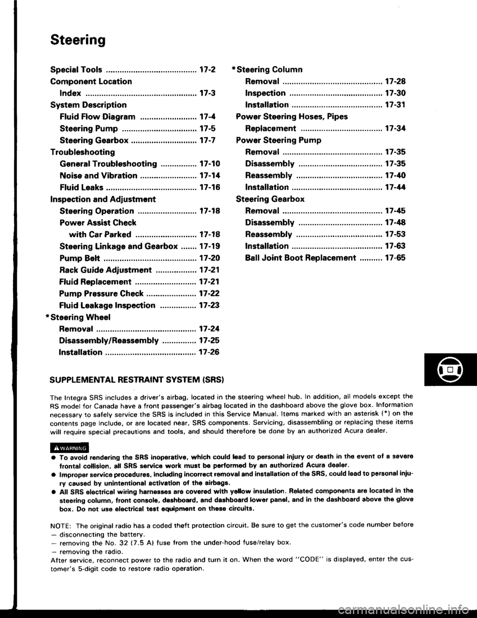
Steering
Special Tools ............. 17-2
Component Location
lndex ................ ...... 17-3
System Description
Ff uid Flow Diagram ......................... 17 -1
Steering Pump ................................. 17-5
Steering Gearbox ............................. 17-7
Troubleshooting
General Troubleshooting ................ 17-10
Noise and Vibration ......................... 17-14
Fluid Leaks ............. 17-16
Inspection and Adiustment
Steoring Operation .......................... 17 -14
Power Assist Check
with Car Parked ........................... 17-18
Steering Linkage and Gearbox ....... 17-19
Pump Beh .............. 17-20
Rack Guide Adjustment ............. ..... 17-21
Ff uid Replacement ...................... ..... 17 -21
Pump Pressure Check .................. .... 17 -22
Ffuid Leakage lnspection ................ 17-23
+ Steering Wheel
Removal ..,,,,,,,........ 17-24
Disassembly/Reassembly ............... 17 -25
fnstallation ,......,,,,,. 17-26
* Steering Column
Removaf .................17-28
Inspection .............. 17-30
Installation ............. 17-31
Power Steering Hoses. Pipes
Replacemont ......... 17-3tl
Power Steering Pump
Removal ................. 17-35
Disassembly .......... 17-35
Reassembly ........... 17-'10
lnstallation ........,..., l7-tltl
Steering Gearbox
Removaf .,.,............. 17-45
Disassembly .......... 17-/E
Reassembly ........... 17-53
lnstallation ............. 17-63
Ball Joint Boot Replacement .......... 17-65
SUPPLEMENTAL RESTRAINT SYSTEM {SRSI
The Integra SRS includes a driver's airbag. located in the steering wheel hub, In addition, all models except the
RS model for Canada have a front passenger's airbag located in the dashboard above the glove box. Information
necessarv to safely service the SRS is included in this Service Manual. ltems marked with an asterisk {') on the
contents page include, or are located near, SRS components. Servicing. disassembling or replacing these items
will require special precautions and tools, and should therefore be done by an authorized Acura dealer.
a To avoid rsndering ths SRS inoporative, which could load to po.sonal iniury 01 d€ath in th€ event ot a ssvare
lrontal collision, all SRS service work muat be performod by an authorizod Acura deal6t.
a lmploper service procodules. including incorloct romoval and installation of the SRS, could lead to personal iniu-
ry caused by unintontional activation ot the airbags.
a All SRS elsctdcal wiring harnesses ara covorod with ysllow insulation. Rolalod compon€nts 8re locatsd in tho
stse ng column, tront console, dashboard, and dashboard lower panel, and in the dashboard above the glove
box. Do not use oloctrical tost equipmoni on thosa cilcuits.
NOTE: The original radio has a coded thett protection circuit. Be sure to get the customer's code number before
- disconnecting the battery.- removing the No. 32 (7.5 A) tuse from the under-hood fuse/relay box.
- removing the radio.
Alter service, reconnect power to the radio and turn it on. When the word "CODE" is displayed' enter the cus-
tomer's 5-digit code to restore radio operation.
Page 610 of 1413
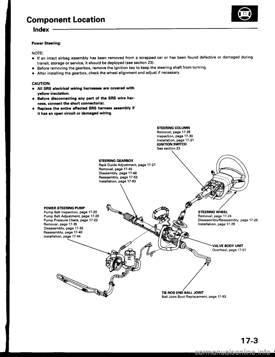
Component Location
lndex
Powar Siooring:
NOTE:
a
a
It an intact airbag ass€mbly has been r€moved from a scrapped car or has been found defective or damaged during
transit. storage or service, it should be doploy€d (see section 23).
Before removing tho gearbox, remove ths ignition key to keep the steering shaft Jrom turning.
After installing the gearbox, check ths whe€l alignment and adiust if necessary.
CAUTION:
. All SRS aloctricll wiring h!m!|$a rrc covcred with
yrllow in3uhtion.
. 8€for€ disconnocling lny ptrt ol thc SRS wiro h!r'
ne*r, connect thc lhort conncctor{3l.
. Rcplsce lhc ontira ttfact d SRS harnccc a$embly il
it hs3 !n oprn circuh 01 dtm!9.d wiring.
SIEERING COLUiINRemoval, page 17-28Inspection, pago 17-30Installation, p6ge 17-31rcNMON SwlTCHSee s6ction 23
STEERII{G GEARBOXRack Guide Adjustment, pag.11-21
Removal, pags 17-45Diossombly, page 17-{8Bea65€mbly, page 17-53Installation, page 17-63
POWEN STEERING PUMPPump Beft Inspoction. page 17-2OPump Eeft Adjustm6nl, pago 17-2OPump Pressurg Ch€ck, page 17-22Removai, p6go 17-35Disassembly, p3gs 17-35Reassombly, psge l7-40lnstallation, page 17-44
STEERING WHEELRemoval. page 17-24Oisassembly/Reassembly, pageInstallation, page 17-2617-25
TIE'ROD END BALL JOINTBall Joint Eoot Replacement, page 17-63
17-3
Page 619 of 1413
Troubleshooting
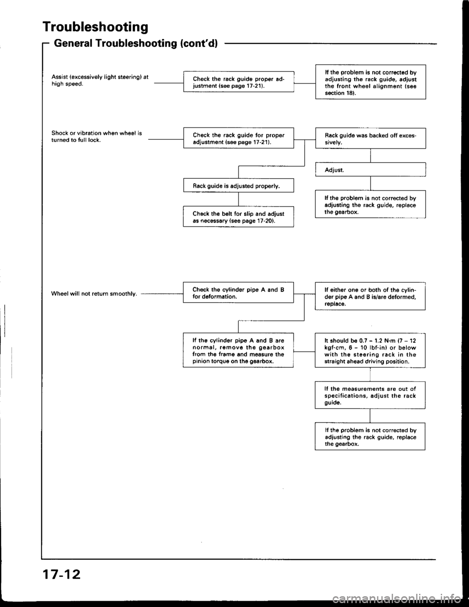
General Troubleshooting {cont'd}
Assist (excessively light steering) athigh speed.
Shock or vibration when wheel isturned to tull lock.
Wheelwill not return smoolhly.
ll the problem is not corrected byadjusting th6 rack g!ide. adjustthe front wheel alignment (see
section 18).
Check the rack guido proper ad'justment (see pago 17-21).
Check the rack guide tor properadjustment (ses psge 17-21).
Rack guide is adjusted prop€rly.
lf th€ problem is not correct€d byadiusting the rack guide, roplacethe gesrbox.Ch6ck the belt tor slip and adjustas nocessary (see page 17-20).
lf oither one or both of the cylin-der pip€ A and B is/are deformed,rsplace,
lf the cylinder pip6 A and B arenormal, remove the gearboxfrom th€ f.ame and mossure thepinion torqug on the gearbox.
It should be 0.7 - 1.2 N.m {7 - 12kgf.cm, 6 - 10 lbf.in) or belowwith the sleering rack in thestraight ahead driving position.
lf lhe measurem€nts are out ofspecilications. adjust the rackguid6.
ll ihe problem is not corrected byadjusting the rack guide, replaceihe gearbox.
17-12
Page 621 of 1413
Troubleshooting
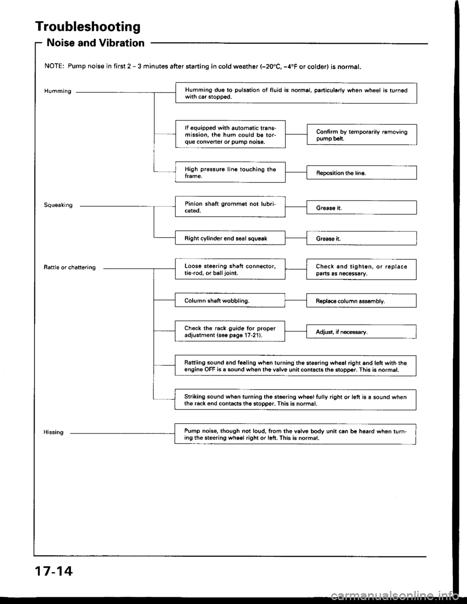
Noise and Vibration
NOTE: Pump noise in first 2 - 3 minutes after starting in cold weather (-20.C, -4"F or colder) is normal.
Humming
Rattle or chattering
Right cylinder end soal squeak
Pump noise. though not loud,lrom the vslvo bodv unit can be heard when turn-ing the steering wheel right or left. This is normsl.
Humming due to pulsation ol fluid is no.mal, paniculady when wheel is turnedwith ca. stopped.
lf equipped with automatic trans-mission, the hum could b€ tor-que convener or pump notse.
Confirm by temporarily removingpump b€lt.
High pressure line touching theframe,Reposhion tho line.
Loose steering shaft connector.tie-rod, or balljoint.Check and tighten, or replacepa s as necessary.
Column shaft wobbling.Replace column assembly.
Check the rack guide for properadjustment (16o page 17-21).Adjust, if n€ca€ssry.
Rattling sound and feeling when turning the steoring wheel right and lett with thoengine OFF is a sound when th6 valve unit contacts tho stopper. This is normal.
Striking sound wh6n turning the ste€ring whoglfully right o. left is a sound whenthe r6ck end contacts th6 stopper. This is normal.
17-14
Page 625 of 1413
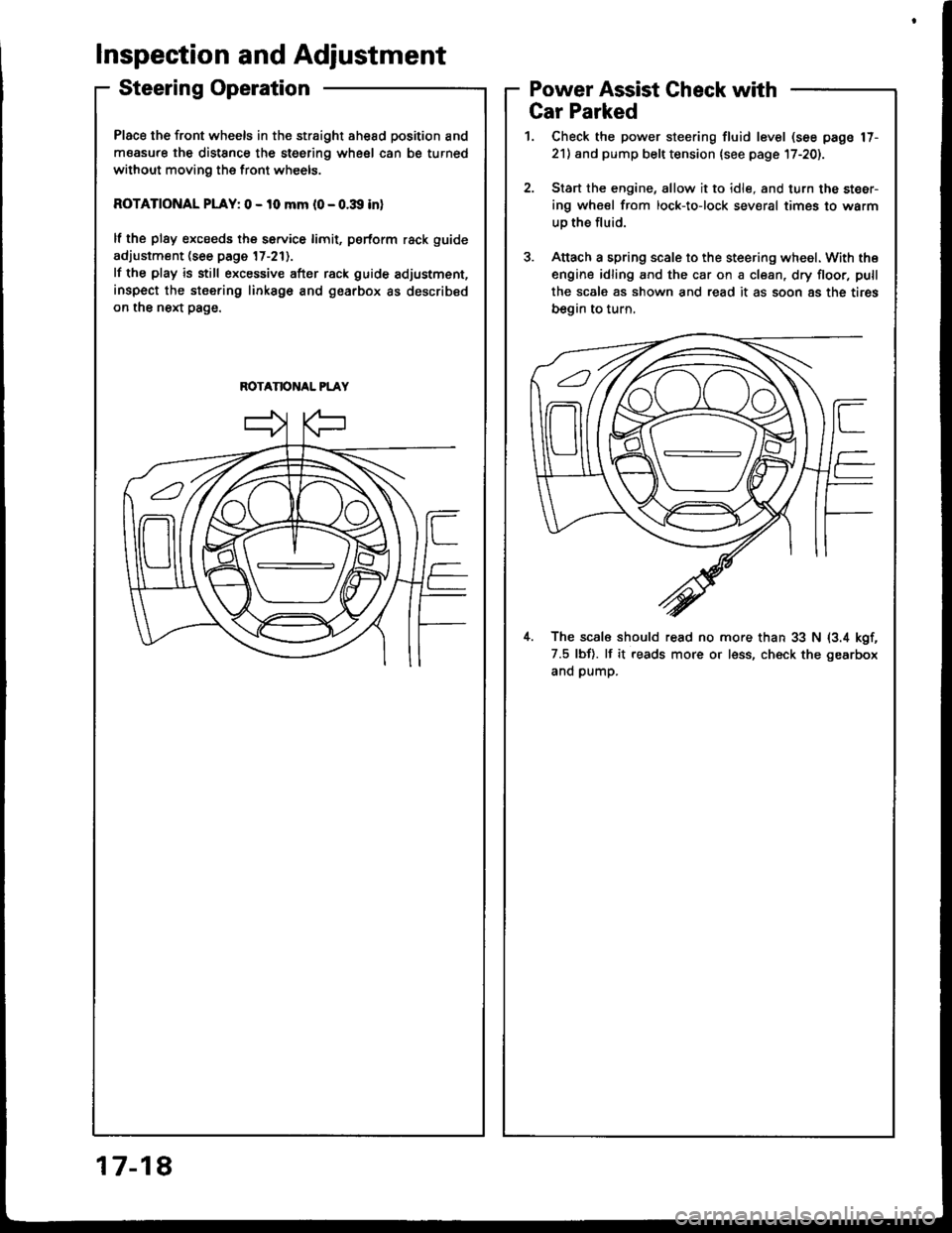
Place the front wheels in the straight ahesd position and
measure the distSnce the steering wheel can be turned
without moving the front wheels.
ROTATIONAL PLAY: 0 - 10 mm l0 - o.:Xl inl
lf the plsy excseds the service limit, psrform rack guide
adjustment (see page 17-211.
lf the play is still excessive after rack guide adjustment,
inspect the stsering linksgo and gearbox as described
on the next page.
ROTANONAL PLAY
Inspection and Adjustment
Steering OperationPower Assist Gheck with
817-1
Gar Parked
1. Check the power steering fluid level (see page 17-
21) and pump belt tension lsee page l7-20).
2.Start the engine, allow it to idle, and turn the steer-
ing wheel from lock-to-lock sev€ral times to warm
uo the fluid.
Attach a spring scale to the steering wheel. With the
engine idling and the car on a clean, dry floor, pull
the scale as shown and read it as soon 8s the tires
begin to turn,
il. The scal6 should read no more than 33 N (3.4 kgf,
7.5 lbf). lf it reads more or less, ch€ck the gearbox
and pump.
Page 627 of 1413
Inspection and Adjustment
Pump Belt
NOTE: When using a new b€li, first adiust the deflection
or t€naion to the values for the new belt, thsn readiust
ths deflection or tension to the values tor the used b€lt
after running sngine for five minutss.
lnspoction
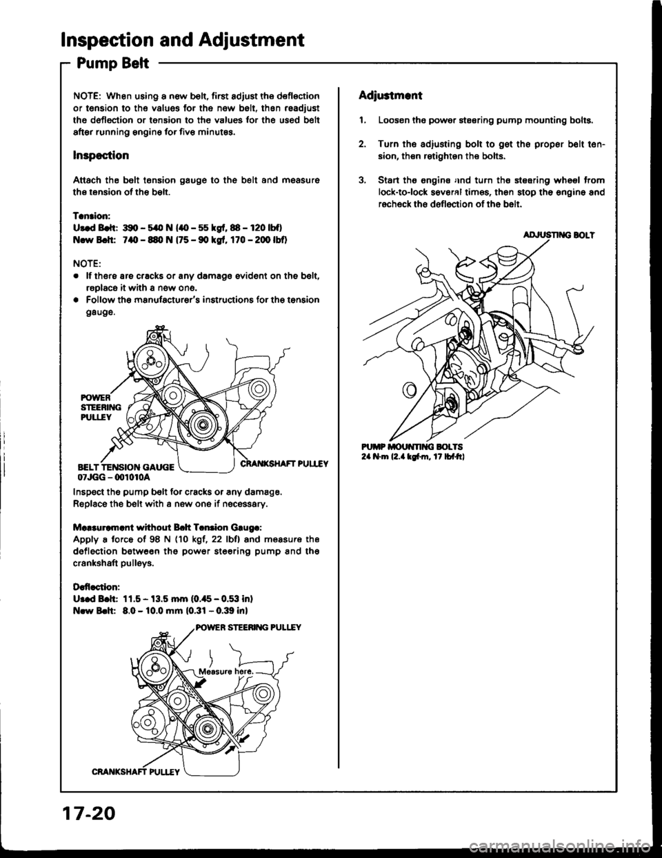
Attach th€ belt tonsion gauge to th6 belt and measure
ths tension of the bslt.
Tanaion:
U3.d Brft: 391, - 5/O N (lO - 55 kgf, 88 - r20 |bf)
Ncw Bch: 7aO - 89, N (75 - 90 kgt, 170 - 20O lbO
NOTE:
. lf thsre are cracks or any damage evident on the belt,
raplaca it with a now ono.
. Follow the manufacturer's insructions for the tonsion
g8uge.
PUII"EY
07JGG - 00r0r0a
Inspect the pump belt for cracks or any damage.
Replace the belt with a new one if nec€ssary.
Mc!3uramrnl without Bch Tcntion Grugr:
Apply a torce of 98 N (10 kgl, 22 lbll and measure ths
deflection between tho power ste€rin9 pump and tho
crankshaft pulleys.
Daffaction:
U:ed Bch: 11.5- 13.5 mm (0.,t5-0.53 inl
Nlw Brh: 8.0 - 10.0 mm (0.31 - 0.39 inl
here,
17-20
Adiu3tmant
1, Loosen the power stesring pump mounting bolts.
2. Turn ths adiusting bolt to gst the propor bolt ten-
sion, then rstighten the bolts.
3, Start ths €ngine and turn the steering wheel trom
lock-tolock s€veral times, then stop the engino and
recheck ths deflection of the belt.
AD'USN G BOLT
Page 628 of 1413
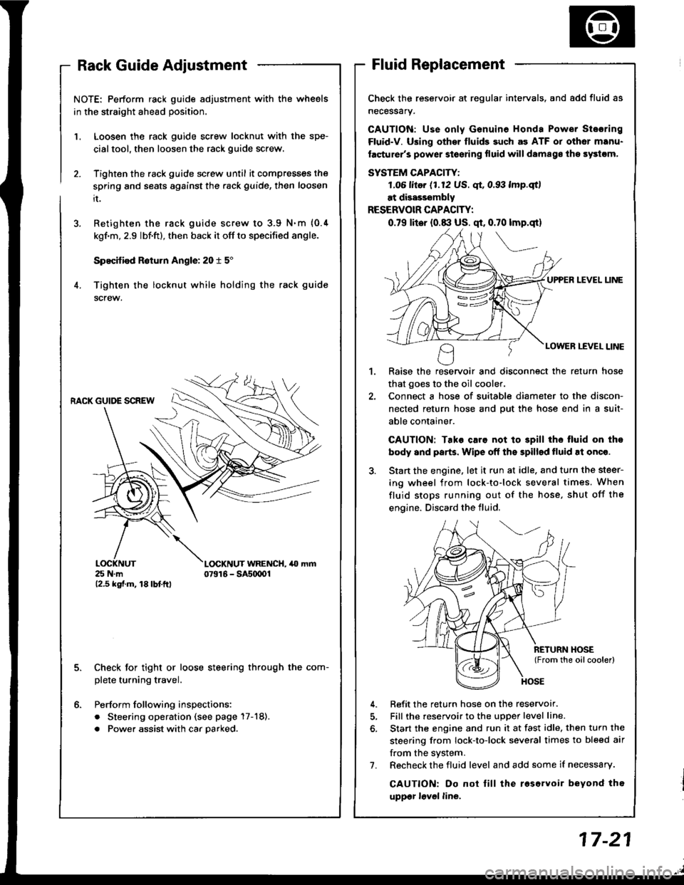
NOTE: Perform rack guide adjustment with the wheels
in the straight ahead position.
Loosen the rack guide screw locknut with the spe-
cialtool, then loosen the rack guide screw.
Tighten the rack guide screw until it compresses the
spring and seats against the .ack guide, then loosen
it.
Retighten the rack guide screw to 3.9 N.m {0.4
kgf'm, 2.9 lbf.ft), then back it off to specified angle.
Specified R6turn Angle: 20 t 5"
Tighten the locknut while holding the rack guide
screw.
1.
6.
RACK GUIDE SCREW
25 N.m12.5 kgf.m, 18lbtftl
L(rcKNUT WRENCH, 40 mm07916 - SAs(xtOl
Check for tight or loose steering through the com-
plete turning travel.
Perform following inspections:
. Steering operation (see page 17-18).
. Power assist with car parked.
Check the reservoir at regular intervals. and add fluid as
necessary.
GAUTION: Use only Genuine Honda Power Stosring
Fluid-V. Using othsr fluids such as ATF or other manu-
facturer's power stoering fluid will damags ths systcm,
SYSTEM CAPACITY:
LO6 litor (1.12 US. qt, 0.93 lmp.qtl
at disasssmbly
RESERVOIR CAPACITY:
0.79 lit6r (0.8:l US. qt, 0.70 lmp.qt)
UPPER LEVEL UNE
LOWER LEVEL LINE
,l
Raise the reservoir and disconnect the return hose
that goes to the oil cooler.
Connect a hose of suitable diameter to the discon-
nected return hose and put the hose end in a suit-
able container.
CAUTION: Tako caro not to 3pill tho tluid on tho
body and parts. Wipe off the spilled tluid at onqe.
Start the engine. let it run at idle. and turn the steer-
ing wheel from lock-to-lock several times. When
fluid stops running out of the hose, shut off the
engine. Discard the fluid,
Refit the return hose on the reservor.
Fill the reservoir to the uDoer level line.
Start the engine and run it at fast idle, then turn the
steering from lock-to-lock several times to bleed air
f.om the system.
Recheck the fluid level and add some if necessary.
CAUTION: Do not lill the roservoir beyond tho
uppgr lovel line.
7.
Page 629 of 1413
lnspection and Adjustment
Pump Pressure Check
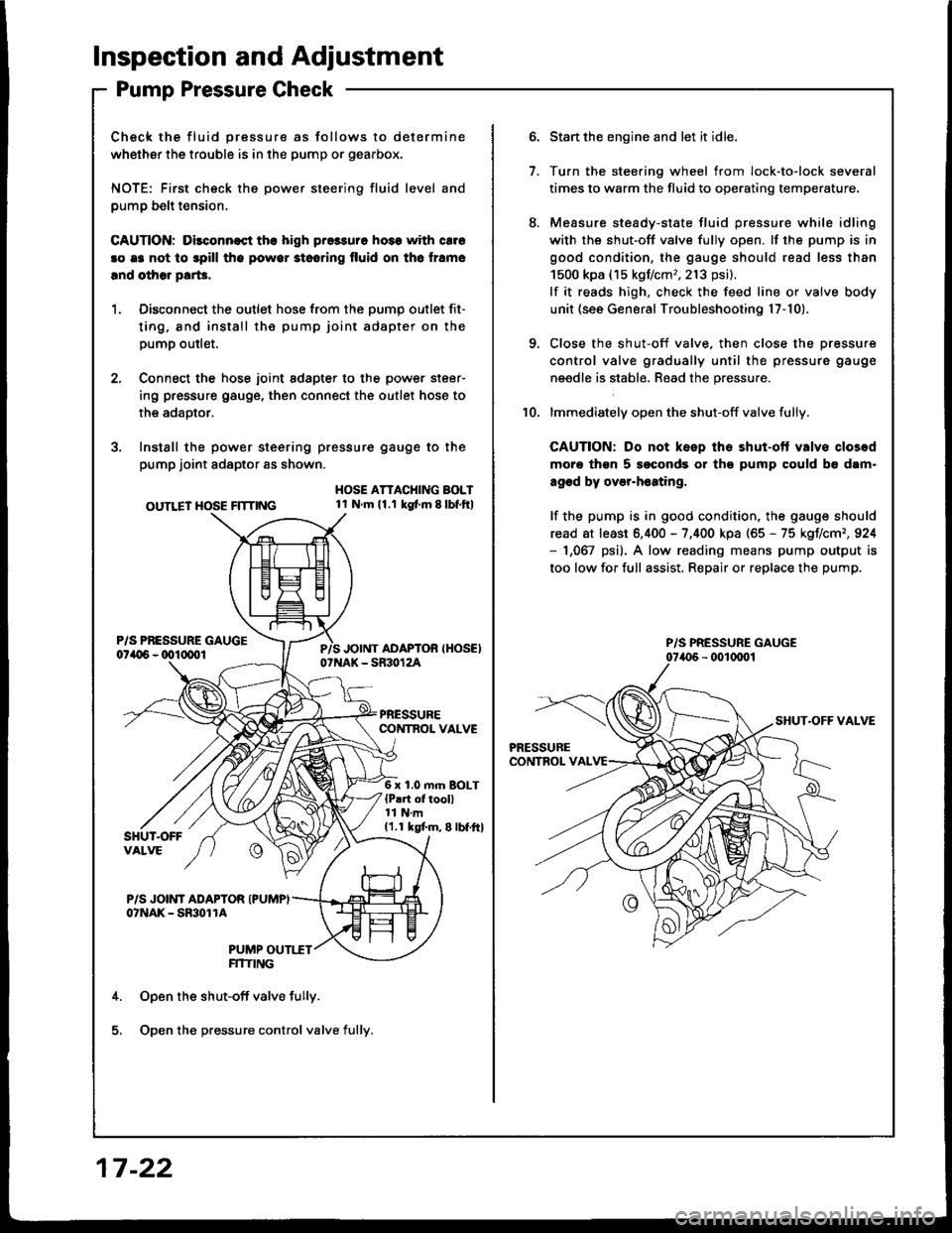
Check the fluid pressure as follows to determine
whether the trouble is in the pump or gearbox.
NOTE: First check the power steering fluid level and
pump belt tension,
CAUnON: Dilconn€st the high pros3uro ho3s with cale
!o e3 not to spill tho powor stooring fluid on th6 lramo
lnd olhor parG.
1. Disconnect the outlet hose from the oumo outlet fit-
ting, 8nd install the pump joint adapter on the
pump outlet.
2, Connect the hose joint sdapter to the power steer-
ing pressure gauge, then connect the outlet hose to
the adaotor.
3. Instsll the power steering pressure gauge to the
pump joint adaptor as shown.
OUTLET HOSE FlTnNG
HOSE ATTACHING BOLT1l Nm11.1 kg{ m 8lbf.ftl
6 x 1.0 m.n BOLT{P!rt of tooll11 N.m11.1 kgtm,8lbf.ftl
P/S JOINT ADAPTOR IPUMPIo?NAK - SmolrA
PUMP OUTI.TTFITIING
Open the shut-off valve fully.
Open the pressure control valve fully.
17 -22
1.
Start the engine and let it idle.
Turn the stee.ing wheel from lock-to-lock several
times to warm the fluid to operating temperature.
Measure steady-state fluid pressure while idling
with the shut-off valve fully open. lf the pump is in
good condition, the gauge should read less than
1500 kpa (15 kgf/cm,,213 psi).
lf it reads high, check the feed line or valve body
unit (see General Troubleshooting l7-10).
Close the shut-off valve. then close the pressure
control valve gradually until the pressure gauge
needle is stabl6, Read the pressure.
lmmediately open the shut-off valve fully.
CAUTION: Do not keep the shut-ott valvs closod
moro thgn 5 soconds or th9 pump could b6 dam"
agod by over-h6ating,
lf the pump is in good condition, the gauge should
read at least 6.400 - 7,400 kpa (65 - 75 kgIlcm,,924- 1,067 psi). A low reading means pump output is
too low for full assist. Repair or replace the pump.
10.
P/S PRESSURE GAUGE
Page 1224 of 1413
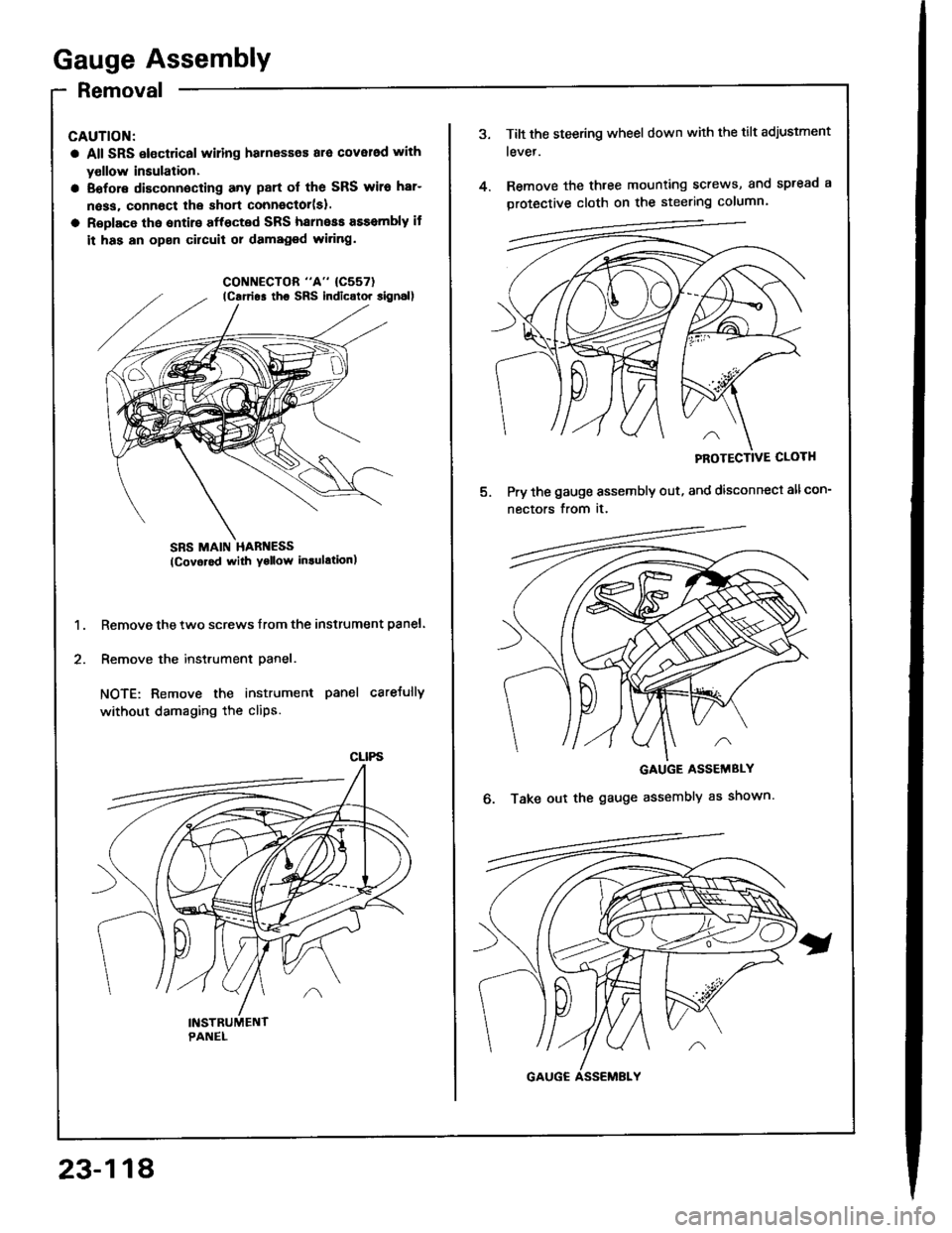
Gauge Assembly
Removal
CAUTION:
a All SRS electrical wiling harnesses ara cover6d with
yollow insulation.
a Eofore disconnecting any part ol the SRS wiro har-
n6ss, connoct lhe short connector(sl.
a Roplace tho entirs affocted SRS harneas assembly if
it has an open circuit 01 damaged wi.ing.
SBS MAIN HARI{ESS(Covor6d with Yollow in.ulationl
Remove the two screws lrom the instrument panel.
Remove the instrument panel.
NOTE: Remove the instrument panel careJully
without damaging the cliPs.
1.
2.
lcarrio. tho SRs indicolor 8ignal)
CLIPS
23-118
Tilt the steering wheel down with the tilt adjustment
tevet.
Remove the three mounting screws, and spread a
protective cloth on the steering column.
PROTECTIVE CLOTH
Pry the gauge assembly out, and disconnect allcon-
nectors from it.
GAUGE ASSEMBLY
Take out the gauge assembly as shown.o.
Page 1379 of 1413
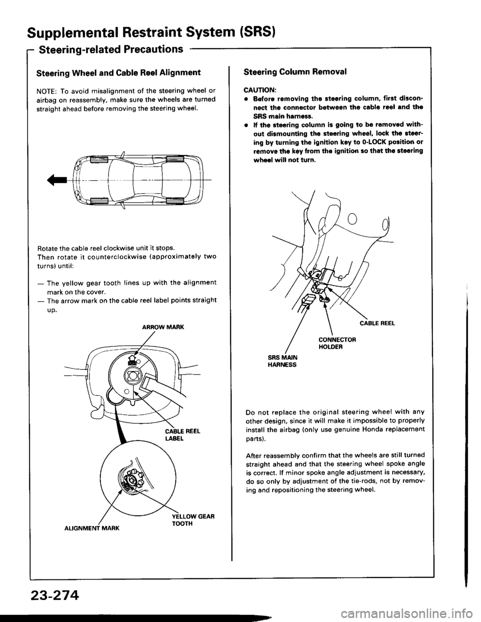
Supplemental Restraint System (SRS)
Steerin g-related Precautions
Steering Wheel and Cable Reel Alignment
NOTE: To avoid misalignment of the steering wheel or
airbag on reassembly, make sure the wheels are turned
straight ahead before removing the steering wheel.
Rotate the cable reel clockwise unit it stops.
Then rotate it co u nterclockwise (approximately two
turnsl until:
- The yellow gear tooth lines up with the alignment
mark on the cover.- The arrow mark on the cable reel label points straight
up.
ALIGNMENT MARK
ARROW MARK
23-274
Steering Column Removal
CAUTION:
. Bofore romoving tho 3l6oring column, first discon'
nect tha connector between ths cablo 16ol snd tho
SRS main harness.
. lf th6 stssring column is going to be removed with-
out dbmounting the stesring wh6el, lock the sl6sr-
ing by turning th€ ignition k.y to o-LOCK po3ition or
removo tha k€y llom ths ignilion so that th6 3loaring
wheel will not turn.
Do not replace the original steering wheei with any
other design, since it will make it impossible to properly
instsll the airbag (only use genuine Honda replacement
oans).
After reassemblv confirm that the wheels are still turned
straight ahead and that the steering wheel spoke angle
is correct, lf minor spoke angle adjustment is necessary,
do so only by adjustment of the tie-rods, not by remov-
ing and repositioning the steering wheel.