vehicle speed sensor HONDA INTEGRA 1994 4.G Workshop Manual
[x] Cancel search | Manufacturer: HONDA, Model Year: 1994, Model line: INTEGRA, Model: HONDA INTEGRA 1994 4.GPages: 1413, PDF Size: 37.94 MB
Page 194 of 1413
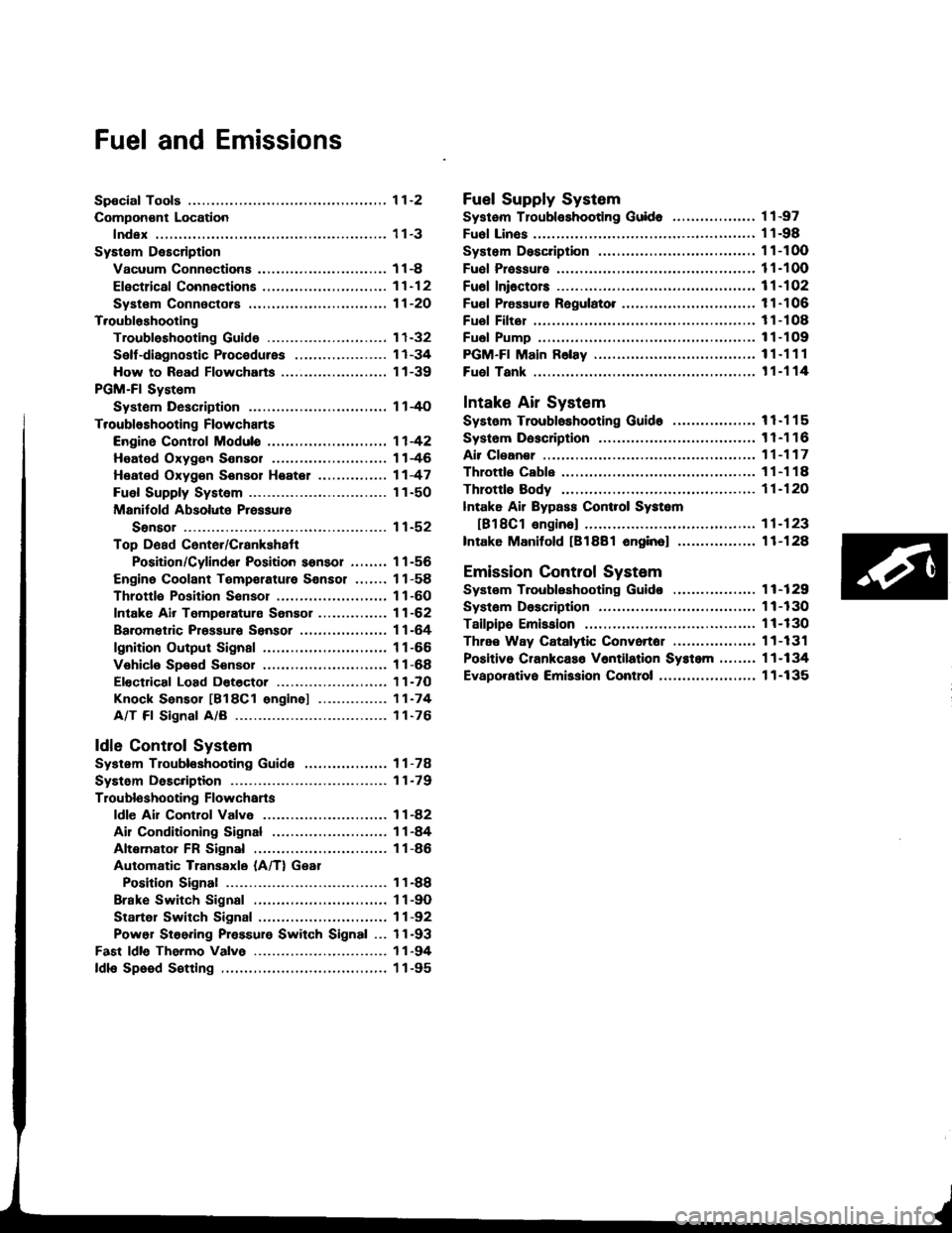
Fuel and Emissions
Spocial Tools ................ 1 1-2
Compon€nt Location
lndex ................. ...... 11-3
System Description
Vacuum Connectiona .......,.................... 1 1 -8
Efectrical Connections ....,.,.,......,...,,.....,'11-12
Syst€m Connectors ...,...,.................-.--. 11-2O
T.oubloshooting
Troubleshooting Guido .......................... 1 1-32
Self -diagnostic Procedures .,..,............... 1 1 -34
How to Road Flowcharts ...................,... 11-39
PGM-Fl System
Systom Description .............................. 1 l-4O
Troubleshooting Flowcharts
Engine Control Moduls ............... ........... 1 1 -42
Heated Oxygon Sensor ......,.................. 1 1-46
Heated Oxyg€n Sonsol Heatel .....,......... 1 1 -47
Fuel Supply System ..............-............... 1 1-50
Manitold Absolute Pressure
Ssnsor ............................................ 1 1-52
Top D6ad Cente./Crankshatr
Position/Cylindor Position sonsor ........ 1 1 -56
Engine Coolant Tempsrature Sonsor ....... 11-58
Throttlo Position Sonsor ........,..,,........... 1 1-60
Intake Air Temperaturs Sensor ............... 11-62
Baromet c Prsssuro Sensor ......,...,...,..,. 11-64
lgnition Output Signal ........................... 1 1 -66
Vehicle Spe€d Sensor ........................... 1 1 -68
Electdcal Load Dotector ....,...,..........,.... 1 1 -7O
Knock Sensor [818C1 engine] ............... 11-74
A/T Fl Signal A/B ................................. 1 1-76
ldle Contlol System
System Troubleshooting Guide .................. 1 1 -78
Systom Description ........ 11-79
Troubloshooting Flowchans
ldl€ Ail Control Valve ........................... 1 1 -82
Ail Conditioning Signal ......................... 1 1 -84
Altemator FR Signal ............................. 1 1 -86
Automatic Transaxle (A/T) Gear
Position Signal ......... 11-88
Brake Switch Signal ............................. 1 1 -9O
Startel Switch Signal ............................ 11-92
Power Steering Pressure Switch Signal ... 11-93
Fast ldle Thermo Valve ...................,......... 1 1 -94
ldls Speed S€tting .................................... 1 1 -95
Fuel Supply System
Systam Tloubloshooting Guid. .................. 1 1 -97
Fuol Linos ...................... 1'l -98
System Description ........ 11-100
Fuol Prassure ................. 11-100
Fu6l Ini6ctors ................. 11-102
Fuel Pressure Ragulato. .,. 11-106
Fuel Filter ...................... 11-108
Fual Pump ..................... 11-109
PGM-Fl Main F6lay ................................... 1 1"1 1 1
Fuel Tank ...................... t 1-114
Intake Air System
System Troubloshooting Guido .................. 1 1 -1 1 5
Systom Dascription ........ 11-116
Air Clean€r .................... 11-117
Throttls Cable ................'11-118
Throttl8 Body ................ 11-120
lntake Air Bypass Cont.ol Systsm
[B18Cl enginal .,......... 11-123
Intake Manilold [B1881 onginol ................. 11-128
Emission Control System
Systsm Troubleshooting Guido .................. 1 1 -1 29
Systam Doscription ........ 11-130
Tailpips Emission ........... 11-130
Thrae Way Catalytic Convortor ...,...,........., 11-131
Positiva CrankcaEo V6ntilation Systcm .,....., 11-134
Evaporativo Emission Contro|,..,..,.,.,,.,,..,.., 1 1-135
Page 228 of 1413
Troubleshooting
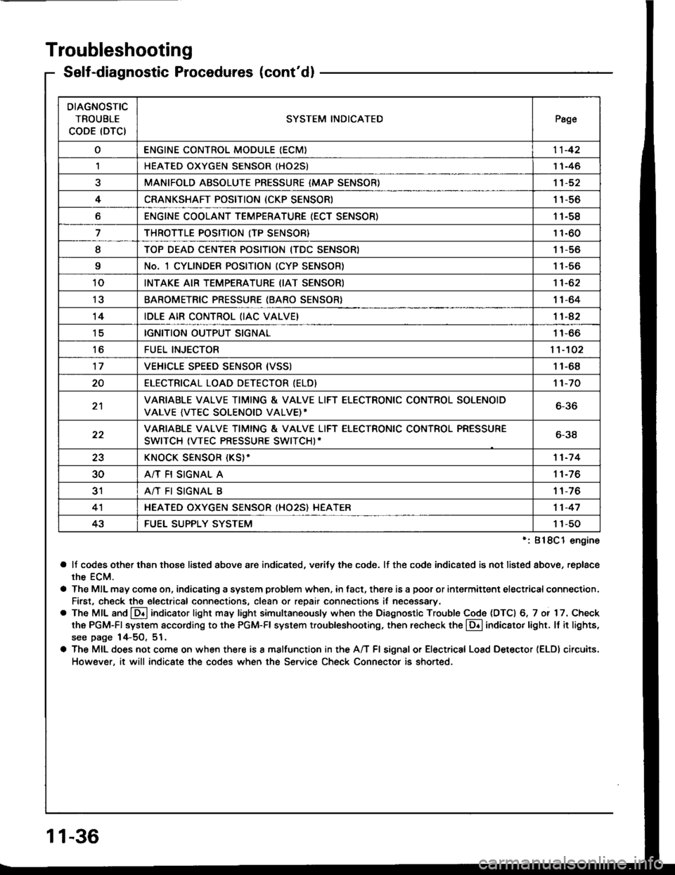
Self-diagnostic Procedures (cont'dl
':818C1 engine
a lf codes other than those listed above are indicated, verifv the code. lf the code indicated is not listed above, replace
rhe ECM.
a The MIL may come on, indicating a system problem when, in fact, there is a poor or intermittent electricalconnection.
First, check the electrical connections, clean or repair connections it necessary.
o The MIL and @ indicator light may light simultaneously when the Diagnostic Trouble Code (DTC) 6, 7 or 17. Check
the PGM-Fl system according to the PGM-Fl system troubleshooting, then recheck the l!! indicator light. ll it lights,
see page 14-5O, 51.
a The MIL does not come on when there is a malfunction in the A/T Fl signal or Electrical Load Detector (ELDI circuits.
However, it will indicate the codes when the Service Check Connector is shorted.
DIAGNOSTIC
TROUBLE
CODE (DTCISYSTEM INDICATEDPsge
oENGINE CONTROL MODULE IECM)11-42
,lHEATED OXYGEN SENSOR IHO25)1 1-46
aMANIFOLD ABSOLUTE PRESSURE {MAP SENSOR)11-52
4CRANKSHAFT POSITION (CKP SENSOR)1 1-56
oENGINE COOLANT TEMPERATURE (ECT SENSOR)11-58
THROTTLE POSITION (TP SENSOR}11-60
ITOP DEAD CENTER POSITION (TDC SENSORI1 1-56
9No. 1 CYLINDER POSITION (CYP SENSOR)1 1-56
10INTAKE AIR TEMPERATURE (IAT SENSOR)11-62
13BAROMETRIC PRESSURE (BARO SENSOR}1|-64
14IDLE AIR CONTROL (IAC VALVE}11-42
tcIGNITION OUTPUT SIGNAL11-66
toFUEL INJECTOR1't-102
17VEHICLE SPEED SENSOR {VSSI11-68
20ELECTRICAT LOAD DETECTOR (ELD)'t 1-70
21VARIABLE VALVE TIMING & VALVE LIFT ELECTRONIC CONTROL SOLENOID
VALVE {VTEC SOLENOID VALVE)'6-36
22VARIABLE VALVE TIMING & VALVE LIFT ELECTRONIC CONTROL PRESSURE
SWITCH (VTEC PRESSURE SWITCHI-6-38
23KNOCK SENSOR {KS}-11-7 4
30A/T FI SIGNAL A11-76
3'rA/T FI SIGNAL B1 1-76
4'lHEATED OXYGEN SENSOR (HO25} HEATER11-47
43FUEL SUPPLY SYSTEM1 1-50
11-36
Page 258 of 1413
PGM-FI System
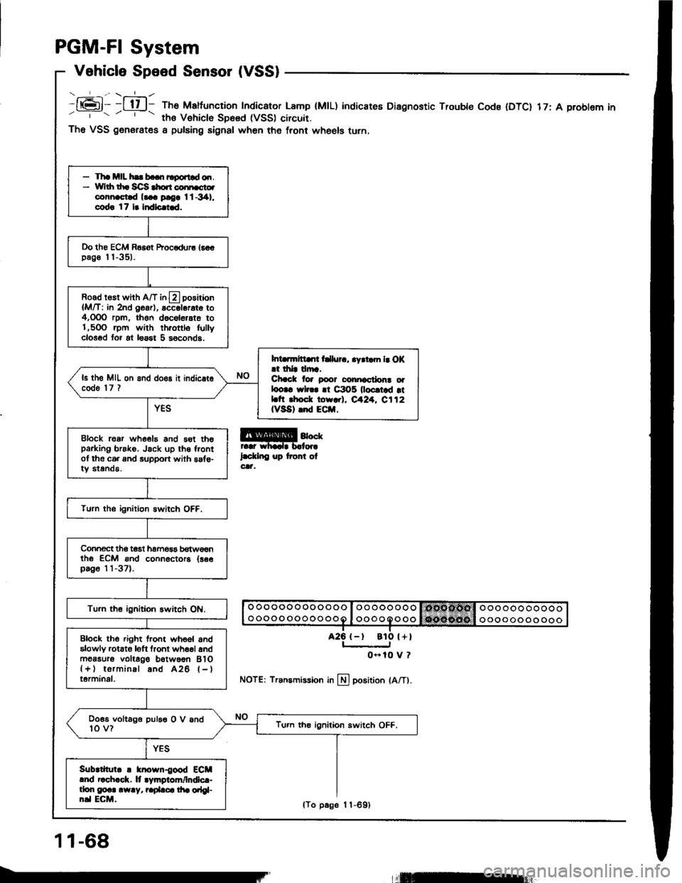
Vehicle Speed Sensor (VSS)
- _-_f_-., \-=1_ -
It6l- -l tl l- The Maltuncrion Indicator Lamp (MtL)' ths Vehiclo SD6sd (VSS) circuit.
indicateE Diagnostic Trouble Code IDTC) 17: A problem in
a25 {-t
The VSS generates a pulsing signal when the front wheels turn.
@4""rr.r whadr b.lor.
l.d.lnC up tront olcat,
NOTE: Transmission in llj position lA/Tl.
- Tha mll hs b..n ltgortld o.r.* Yvlrh th. Sc]S $o.r coi[cto.connast.d l... ploa I l -341,
cod! 17 i. Indlc.i.d.
Do the ECM Basot Procodur6 16€€pag€ I I -351.
Road rosr whh A/T in13 positaon
{M/T: in 2nd O6ar), accol6rat6 to4,OOO rpm, thon d6c6l6,ate to1,5OO .pm with th.ottlo fullyclosod tor at loast 5 s6conds.
Int rmltllrt t llur., .yrtam b O|(.t drlr drr.Chcct lor poor conicctlon! oalootc wl... !t C3O5 0ocrtad rtLtt rhod. torr.l, eA24. C112IVSA) .nd ECil.
ls th6 MIL on and doos it indic.t6code 'l7 ?
Block roar whe€19 and 5st th6parking brsko. Jsck up th€ f.ontof the c6. and support with saf€-iy standa.
Turn the ignition Bwitch OFF.
Connect tho t€st hamos3 b€tw€€ntho ECM ond connoctora {as€pag6 11-37).
Tu.n th€ ignitioh switch ON.
Block the .ight lront whoel andalowly rctato loft tront wh6ol andm6asur6 voltago b€twoon BlO{+) torminal and A26 l-}terminal.
Doss voltago puleo O V and10 v?Tu.n th€ ignition switch OFF.
Sub|tllul. ! knosn{ood ECMlnd r!ch.ck. lt .Vmgiom/lndlc.-tlon g@.. .w.y, r.pLca di. orlgl-n.l ECM.
ato l+l
0- 10 V ?
11-68
lTo p6ge 1 1-691
llEur
Page 391 of 1413
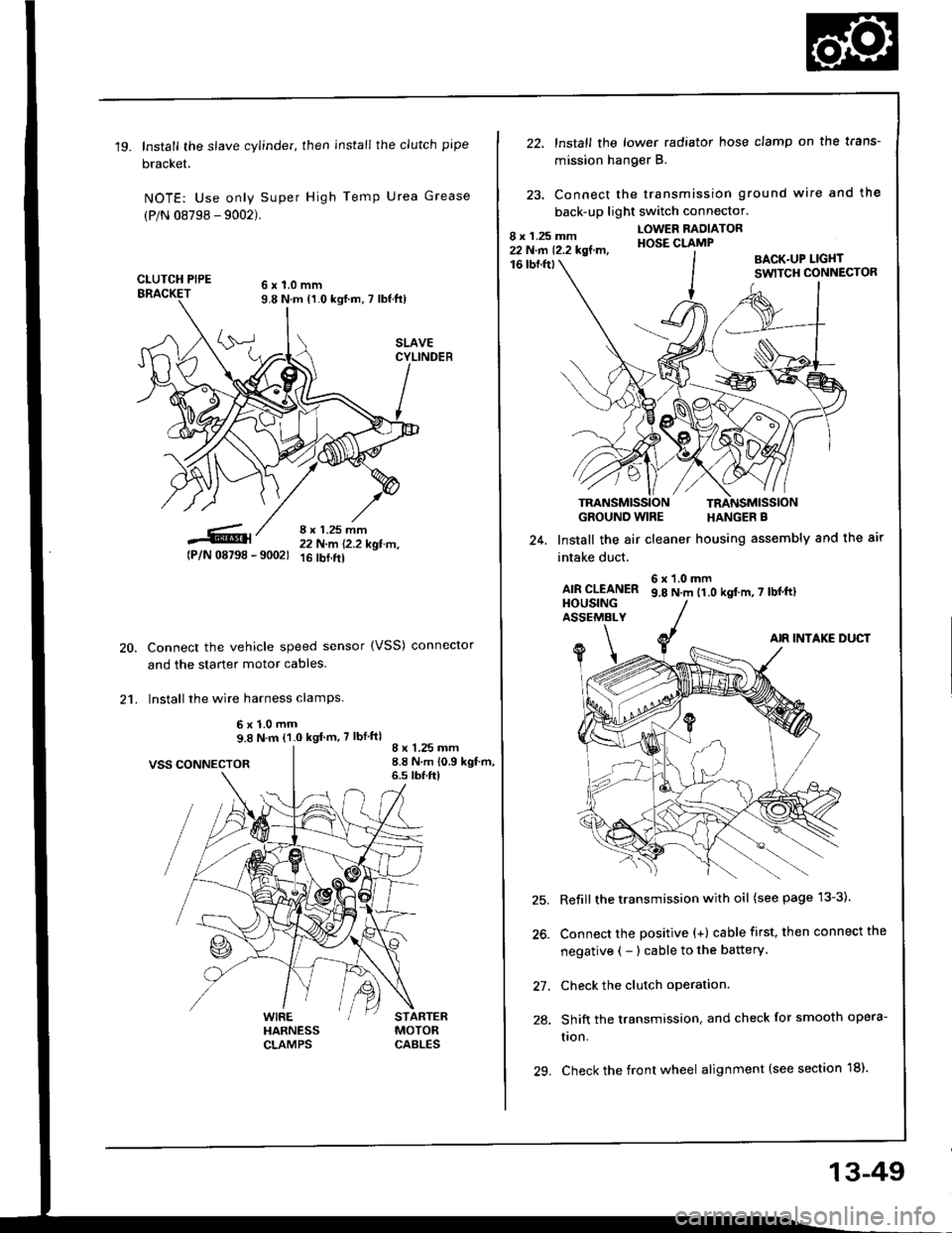
'19.Install the slave cylinder, then install the clutch pipe
bracket.
NOTE: Use only Super High Temp Urea Grease
(P/N 08798 - 9002).
CLUTCH PIPE6x1.0mm9.8 N.m {1.0 kgf.m, 7 lbf ft)
8 x 1.25 mm22 N-m 12.2 kgl.tr't,16 rbf.ftl
20.
21.
tPlN 08798 - 90021
VSS CONNECTOR
Connect the vehicle speed sensor (VSS) conneclor
and the starter motor cables.
Install the wire harness clamPs.
6x1.0mm9.8 N.m (1.0 kgt m,7 lbf ftl
WIREHARNESSCLAMPS
8 x 1.25 mm8.8 N.m 10.9 kgf.m,6.s tbf.ft)
STARTERMOTORCABLES
22, lnstall the lower radiator hose clamp on the trans-
mission hang€r B.
23. Connect the transmission ground wire and the
back-up light switch connector.
16 tbf.fttBACK.UP LIGI{TSWITCH CONNECTOR
GROUND WIRE HANGER B
Install the air cleaner housing assembly and the air24.
intake duct.
AIR CLEANERHOUSINGASSEMALY
6x1.0mm9.8 N.m 11.0 kgt'm,7 lbtftl
AIR INTAKE DUCT
Refill the transmission with oil (see page 13-3).
Connect the positive (+) cable first, then connect the
negative ( - ) cable to the battery.
Check the clutch operation.
Shift the transmission. and check for smooth opera-
tron.
29. Check the front wheel alignment (see section 18).
9\
\<
27.
28.
13-49
Page 397 of 1413
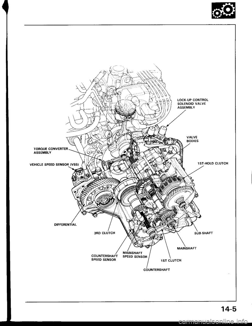
VALVEBODIES
TOROUE CONVERTERASSEMBLY
VEHICLE SPEED SENSOR IVSSI1ST-HOLD CLUTCH
SUB SHAFT3RD CLUTCH
SPEED SENSOR
MAINSHAFT
SPEED SENSOR1ST CLUTCH
COUNTERSHAFT
14-5
Page 411 of 1413
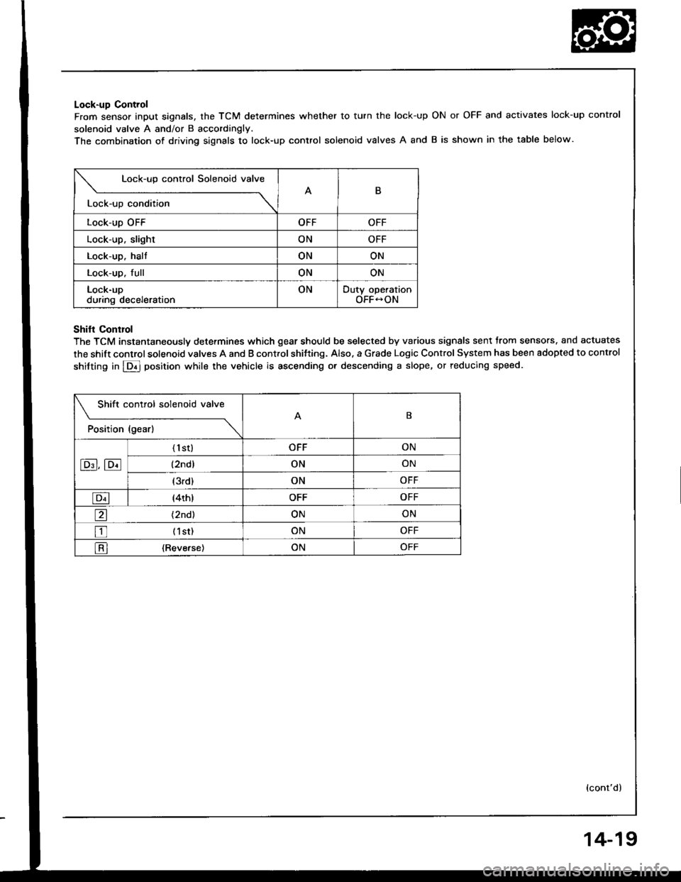
Lock-up Control
From sensor input signals, the TCM determines whether to turn the lock-up
solenoid valve A and/or B accordingly.
The combination of driving siqnals to lock-up control solenoid valves A and
ON or OFF and activates lock-up control
B is shown in the table below.
Lock-up control Solenoid valve
B
Lock-up condition \
Lock-up OFFOFFOFF
Lock-up, slightONOFF
Lock-up. haltONON
Lock-up. fullONON
Lock-upduring decelerationONDuty operationOFF-ON
Shifl Conrrol
The TCM instantaneously determines which gear should be selected by various signals sent trom sensors. and actuates
the shift control solenoid valves A and B control shitting. Also. a Grade Logic Control System has been adopted to control
shifting in E] position while the vehicle is ascending or descending a slope, or reducing speed.
Shift control solenoid valve
t"*b" ,t"-l
------\B
E,E
('l st)OFFON
(2ndlONON
(3rd)ONOFF
E(4th)OFFOFF
a(2nd)ONON
tr (lst)ONOFF
l-Rl {Reverse)ONOFF
(cont'd)
14-19
Page 412 of 1413
Description
Electronic Control System (cont'd)
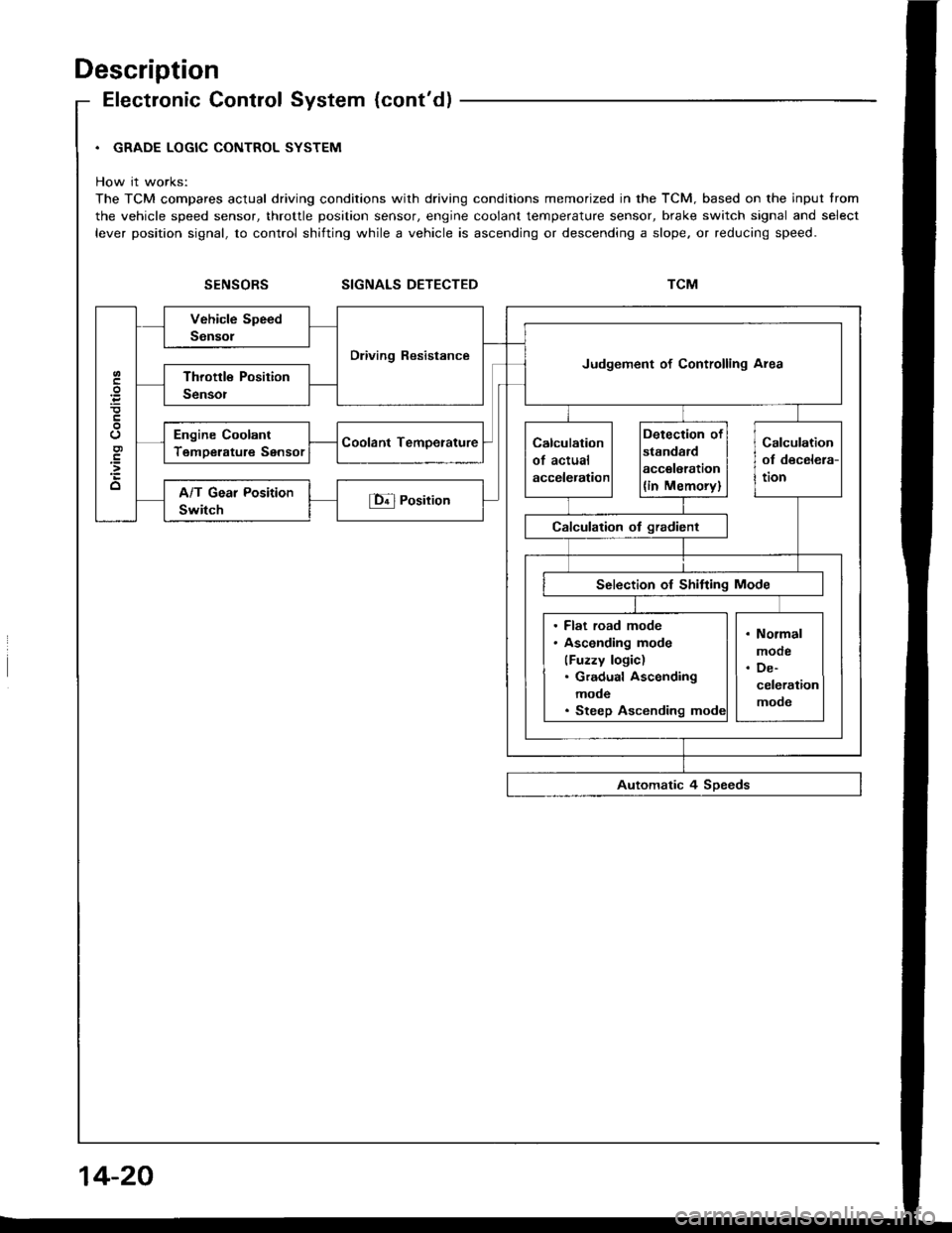
. GRADE LOGIC CONTROL SYSTEM
How it works:
The TCM compares actual driving conditions with driving conditions memorized in the TCM. based on the input trom
the vehicle speed sensor, throttle position sensor, engine coolant temperature sensor, brake switch signal and select
lever position signal, to control shifting while a vehicle is ascending or descending a slope. or reducing speed.
SIGNALS DETECTED
Dliving ResistanceJudgement of Controlling Area
Engine Coolant
TemDerature Sensor
. Flat road mode. Asconding mode
(Fuzzy logic). Gradual Ascending
mode. Steep Ascending
14-20
Page 437 of 1413
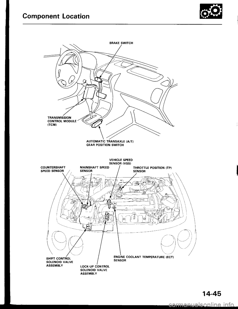
Component Location
)/
,/s\
{7v
A0t
AUTOMATIC TRANSAXLE IA/TIGEAR POSITION SWITCH
VEHICLE SPEEDSENSOR {VSSI
COUNTERSHAFTSPEED SEf{SORMAINSHAFT SPEEDSENSORTHROTTLE POSITION (TP}SENSOR
at
,
)''ENGINE COOLANT TEMPERATURE (ECTISENSOR
14-45
Page 442 of 1413
![HONDA INTEGRA 1994 4.G Workshop Manual Symptom-to-Component Chart
Electrical System
Number of @indicator light
blinks while
Service Check
Connector is
connected with
the special tool.
@] indicaror
lightPossible CauseSymptomRefer to
page
Bl HONDA INTEGRA 1994 4.G Workshop Manual Symptom-to-Component Chart
Electrical System
Number of @indicator light
blinks while
Service Check
Connector is
connected with
the special tool.
@] indicaror
lightPossible CauseSymptomRefer to
page
Bl](/img/13/6067/w960_6067-441.png)
Symptom-to-Component Chart
Electrical System
Number of @indicator light
blinks while
Service Check
Connector is
connected with
the special tool.
@] indicaror
lightPossible CauseSymptomRefer to
page
BlinksDisconnected lock-up control solenoidvalve A connector
Short or open in lock-up control sole-noid valve A wire
Faulty lock-up control solenoid valve A
Lock-up clutch does not
engage.
Lock-up clutch does not
disengage.
Unstable idle speed.
14-52
BlinksDisconnected lock-up control solenoidvalve B connector
Short or open in lock-up control sole-noid valve B wire
Faulty lock-up cont.ol solenoid valve B
. Lock-up clutch does not
enga9e.
14-54
Blinks or
OFF
Disconnected throttle position (Tp)
sensor connector
Short or open in TP sensor wireFaully TP sensor
. Lock-up clutch does not
engage.14-56
4BlinksDisconnected vehicle speed sensor(VSS) connector
Short or open in VSS wire
Faulty VSS
. Lock-up clutch does not
engage.'t 4-57
Blinks. Short in A/T gear position switch wire. Faulty A/T gear position switch
. Fails to shift other than
2nde4th gears.. Lock-up clutch does not
engage.
14-58
OFFDisconnected A/T gear position switch
connector
Open in A/T gear position switch wireFaulty A/T gear position switch
Fails to shift other than
2nd-4th gears.
Lock-up clutch does not
en98ge.
Lock-up clutch engages
and disengages alter-
nately.
14-60
7BlinksDisconnected shift control solenoidvalve A connector
Short or open in shitt control solenoidvalve A wire
Faulty shift control solenoid valve A
. Fails to shift (between
1st-4th, 2nd-4th or
2nd-3rd gears only).. Fails to shift (stuck in
4th gear).
14-62
8BlinksDisconnected shitt control solenoid
valve B connector
Shon or open in shift control solenoidvalve B wi.e
Faulty shift control solenoid valve B
. Fails to shiJt (stuck in
lst or 4th gears).'t 4-64
aBlinksDisconnected countershatt speed sen-sor connector
Short or open in the countershaft
speed sensor wire
Faulty countershaft speed sensor
. Lock-up clutch does not
engage_
14-50
Page 443 of 1413
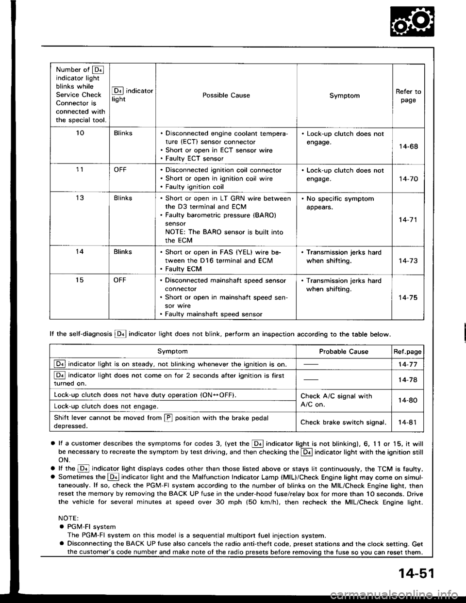
Number of @indicator light
blinks while
Service Check
Connector is
connected with
the special tool.
@ indicator
lightPossible CauseSymptomRefer to
page
'loBlinksDisconnected engine coolant tempera-
rure (ECT) sensor connector
Short or open in ECT sensor wire
Faulty ECT sensor
Lock-up clutch does not
engage.14-68
1lOFFDisconnected ignition coil connector
Short or open in ignition coil wire
Faulty ignition coil
. Lock-up clutch does not
engage.'t 4-7 0
13Blinks. Shon or open in LT GRN wire between
the D3 terminal and ECM. Faulty barometric pressure {BARO)
sensor
NOTE: The BARO sensor is built into
the ECM
. No specific symptom
appears.
14-7 1
14Blinks. Short of open in FAS {YEL} wire be-
tween the D16 terminal and ECM. Faulty ECM
. Transmission jerks hard
when shitting.
't5OFFDisconnected mainshaft speed sensor
connecror
Short or open in mainshaft speed sen-
sor wire
Faulty mainshaft speed sensor
. Transmission jerks hard
when shifting.
14-75
SymptomProbable CauseRet.page
LQ! indicator light is on steady, not blinking whenever the ignition is on.14-77
[Q3] indicator light does not come on for 2 seconds after ignition is first
turned on.14-78
Lock-up clutch does not have duty operation (ON-OFFI.Check A/C signal with
A/C on.14-80Lock-up clutch does not engage.
Shitt leve. cannot be moved lrom @ position with the brake pedal
depressed.Check brake switch signal,14-41
It the self-diagnosis LQ4 indicator light does not blink, perform an inspection according to the table below.
a lf a customer describes the symptoms for codes 3, (yet the LQ! indicator light is not blinkingl, 6, 1 1 or 15, it will
be necessa.y to recreate the symptom by test driving. and then checking the @ indicator light with the ignition still
oN.
e lt ttre @ indicator light displays codes olher than those listed above or stays lit continuously, the TCM is faulty.. Sometimes the Lqd indicator light and the Malfunction Indicator Lamp (MlL)/Check Engine light may come on simul-taneously. lf so, check the PGM-Fl system according to the numbe. of blinks on the MIL/Check Engine light. thenreset the memory by removing the BACK UP fuse in the unde.-hood fuse/relay box for more than 1O seconds. Drive
the vehicle for several minutes at speed over 30 mph (5O km/h), then recheck the MIL/Check Engine light.
NOTE:
. PGM-FI system
The PGM-Fl system on this model is a sequential multiport fuel injection system.a Disconnecting the BACK UP luse also cancels the radio anti-theft code. preset stations and the clock setting. Get
the fuse so vou can reset them.the customer's code number and make note ot the radio
14-51